Table of Contents
Advertisement
Quick Links
The DRV2667 is a digital interface, high-voltage driver designed to control Piezo actuators with voltages
between 40 Vpp and 200 Vpp. The DRV2667 eliminates many design complexities of driving Piezo by
including an integrated 100-Vpp boost converter and 200-Vpp differential output amplifier. In addition, the
digital control interface (I
embedded RAM for waveform storage.
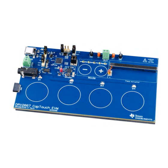
The DRV2667EVM-CT Evaluation Module (EVM) kit is a complete demonstration and evaluation platform
for the DRV2667. The kit includes a microcontroller, Piezo actuator, sample waveforms, and capacitive
touch buttons which can be used to completely demonstrate and evaluate the DRV2667.
This document contains instructions for setup and operation of the DRV2667EVM-CT, as well as an in-
depth description and examples of haptic waveforms for Piezo actuators.
Evaluation kit contents
•
DRV2667EVM-CT demonstration and evaluation board
•
Mini-USB cable
Tools needed for programming and advanced configuration
•
Code Composer Studio™ (CCS) or IAR Embedded Workbench IDE for MSP430
•
MSP430 LaunchPad (MSP-EXP430G2) or MSP430-FET430UIF hardware programming tool
•
DRV2667EVM-CT firmware
This evaluation board contains high voltages, up to 200 Vpp.
Please use the necessary precautions when using this board.
Code Composer Studio is a trademark of Texas Instruments.
2
I
C is a trademark of NXP.
SLOU323 – June 2013
Submit Documentation Feedback
DRV2667 Evaluation Module
2
C™) includes real-time waveform playback, a waveform generator, and
WARNING
Copyright © 2013, Texas Instruments Incorporated
User's Guide
SLOU323 – June 2013
DRV2667 Evaluation Module
1
Advertisement
Table of Contents

Related Manuals for Texas Instruments DRV2667EVM-CT


Summary of Contents for Texas Instruments DRV2667EVM-CT
- Page 1 DRV2667. The kit includes a microcontroller, Piezo actuator, sample waveforms, and capacitive touch buttons which can be used to completely demonstrate and evaluate the DRV2667. This document contains instructions for setup and operation of the DRV2667EVM-CT, as well as an in- depth description and examples of haptic waveforms for Piezo actuators.
-
Page 2: Table Of Contents
DRV2667EVM-CT Power Diagram ................Output Terminal Block and Test Points ......................External I C Input ....................External Analog/PWM Input ................. Boost Voltage Programming Resistors DRV2667 Evaluation Module SLOU323 – June 2013 Submit Documentation Feedback Copyright © 2013, Texas Instruments Incorporated... - Page 3 Boost Voltage using MSP430 GPIO Control ..............Boost Voltage and Gain Settings (R1 and R2 Only) ..................Boost Converter Inductor Selection ......................MSP430 Pin-Out ..................DRV2667EVM-CT Bill of Materials SLOU323 – June 2013 DRV2667 Evaluation Module Submit Documentation Feedback Copyright © 2013, Texas Instruments Incorporated...
-
Page 4: Getting Started
To begin, power the board by connecting the DRV2667EVM-CT to an available USB port using the included mini-USB cable. The board begins with a power-up sequence, and finishes by entering Demo mode. -
Page 5: Evaluation Module Operating Parameters
Selects USB (5 V) for the DRV2667 power rail 2. Connect the mini-USB cable (included) to the USB connector on the DRV2667EVM-CT board. 3. Connect the other end of the USB cable to an available USB port on a computer, USB charger, or USB battery pack. -
Page 6: Drv2667 Embedded Software
DRV2667 Embedded Software The DRV2667EVM-CT contains a microcontroller with embedded software to operate and control the board. The software consists of multiple sets of modes and effects that showcase the features of the DRV2667 driver. There are three sets of modes that are accessed by pressing and holding the "+" button. -
Page 7: Demo Mode
The current mode is indicated by the white LEDs directly above the mode buttons. Buttons B1–B4 trigger the effects listed in the description column and change based on the current mode. Table 3. DRV2667EVM-CT Demo Mode Mode... -
Page 8: Demo Mode Descriptions
Alert 2 is a sequence of two waveforms that produces a buzz and click waveform. Figure 5. B2 – Alert 2 Figure 6. B2 - Alert 2 Continuous Repeat DRV2667 Evaluation Module SLOU323 – June 2013 Submit Documentation Feedback Copyright © 2013, Texas Instruments Incorporated... -
Page 9: B3 - Alert 3
Alert 4 is a single waveform that produces a buzz. Figure 9. B4 – Alert 4 Figure 10. B4 – Alert 4 Continuous Repeat SLOU323 – June 2013 DRV2667 Evaluation Module Submit Documentation Feedback Copyright © 2013, Texas Instruments Incorporated... -
Page 10: B2 - Click And Release 1
The effect on button four is a ramp and release effect. When the button is pressed the waveform ramps up and when released it ramps down. Figure 13. Ramp and Release DRV2667 Evaluation Module SLOU323 – June 2013 Submit Documentation Feedback Copyright © 2013, Texas Instruments Incorporated... -
Page 11: B1 - Ramp Up
Button 4 – Pulse Button 4 consists of two waveforms a ramp up and ramp down. This produces a pulsating effect. Figure 16. B4 – Pulse SLOU323 – June 2013 DRV2667 Evaluation Module Submit Documentation Feedback Copyright © 2013, Texas Instruments Incorporated... -
Page 12: B1 - Sharp Click Using Fifo
If you choose to use the embedded RAM you can create waveforms like the two-tone robotic click waveform in Figure Figure 19. B4 – Robotic Click using RAM DRV2667 Evaluation Module SLOU323 – June 2013 Submit Documentation Feedback Copyright © 2013, Texas Instruments Incorporated... -
Page 13: B3 - Audio In
2.2.6 Mode 0 – Analog or Audio Input Mode 0 allows you to connect an analog input source to the DRV2667EVM-CT. See Analog/PWM Input for the hardware configuration. This shows the advantage of Piezo over other actuator technologies. Piezo actuators have a much faster response time than ERM and LRA actuators, so the Piezo actuator can be driven with an analog or audio signal and reproduce the input frequencies well. -
Page 14: Ram Library Mode
Table 4 for a list effects stored in the DRV2667 RAM. RAM Library Effects List Table 4 is a description of the effects stored in the DRV2667 RAM. Table 4. DRV2667EVM-CT Library Modes Effect ID Waveform Name Click150 Click200 Click250... - Page 15 DRV2667 Embedded Software www.ti.com Table 5 lists the modes available for design and testing. Table 5. DRV2667EVM-CT Binary Modes Mode Button Description Notes Mode 0 Memory store enabled GUI Mode – use this mode to trigger and store the sequencer set by a GUI. Store the GUI Mode sequencer by first pressing B1 (the mode LEDs turn on).
-
Page 16: Return To Demo Mode
2. Release the button when the actuator buzzes and the mode LEDs flash. 3. Select from the Demo modes using the "+" and "–" buttons. DRV2667 Evaluation Module SLOU323 – June 2013 Submit Documentation Feedback Copyright © 2013, Texas Instruments Incorporated... -
Page 17: Hardware Configuration
External Supply Power (3.0 V–5.0 V) Power Power Supply The DRV2667EVM-CT can be powered by USB or an external power supply (VBAT). Jumpers DRV and MSP are used to select the supply for the DRV2667 and the MSP430G2553, respectively. See the Table 7 for configuration options. -
Page 18: External Actuator
OUT+ From DRV2667 Figure 22. Output Terminal Block and Test Points The DRV2667EVM-CT can be used with an external actuator. Follow the instructions below to attach an actuator to the OUT terminal block. 1. Ensure the board is powered down. -
Page 19: Analog/Pwm Input
SDA SCL Figure 24. External Analog/PWM Input The DRV2667EVM-CT accepts analog or PWM inputs for the analog IN+/IN- pins of the DRV2667. To use the IN+/IN- pins of the DRV2667 follow the instructions below: 1. Enter Design & Test Modes. Select Mode 7 (00111’b) using the increment mode button (“+”). -
Page 20: Boost Voltage Programming Resistors
19.1 kΩ 12.8 kΩ 9.8 kΩ To change the default boost voltage on the DRV2667EVM-CT using the embedded software, follow the instructions below: 1. Enter Design & Test Modes. 2. Select Mode 30 (11110’b) using the increment mode button (“+”). - Page 21 Inductance (µH) ISAT (A) (Ω) Coilcraft LPS4018- 0.08 7.32 k 332MLB Coilcraft LPS4018- 0.125 7.5 k 472MLB VLS3012T- 0.100 9.31 k 3R3M1R3 VLS3010 0.130 11 k 1.28 SLOU323 – June 2013 DRV2667 Evaluation Module Submit Documentation Feedback Copyright © 2013, Texas Instruments Incorporated...
- Page 22 For example, when 50 V is applied to a 100-V rated capacitor, the capacitance will decrease by about 50%. Most capacitor vendors provide a capacitance versus voltage curve for reference. DRV2667 Evaluation Module SLOU323 – June 2013 Submit Documentation Feedback Copyright © 2013, Texas Instruments Incorporated...
-
Page 23: Msp430 Control And Firmware
Create a new MSP430 project in IAR • Select the MSP430G2553 device • Copy the .h and .c files in the DRV2667EVM-CT project folder downloaded from ti.com into the new project directory SLOU323 – June 2013 DRV2667 Evaluation Module Submit Documentation Feedback... - Page 24 MSP430 Control and Firmware www.ti.com MSP430 Actuator ANALOG DRV2667 EMULATION MSP-EXP430G2 Figure 26. DRV2667EVM-CT LaunchPad Connection DRV2667 Evaluation Module SLOU323 – June 2013 Submit Documentation Feedback Copyright © 2013, Texas Instruments Incorporated...
-
Page 25: Msp430 Pin-Out
MSP430 Control and Firmware www.ti.com MSP430 Pin-Out The DRV2667EVM-CT contains an MSP430G2553 low-cost microcontroller which controls the board and contains sample haptic effects. The pin-out for the microcontroller is found in Table Table 11. MSP430 Pin-Out Label Description P1.1 Green LED P1.2... -
Page 26: Schematic, Printed-Circuit Board Layouts, And Bill Of Materials
0.1ufd/100V PowerPad 0402 3.3uH/1.1A 1206 X7R VLS3010 Black Black +3.3V PowerPad 0.1ufd/25V 0603 GAIN0 0.1ufd/16V 0402 SC70-6 60V 115mA QFN32-RHB Figure 27. DRV2667EVM-CT Schematic DRV2667 Evaluation Module SLOU323 – June 2013 Submit Documentation Feedback Copyright © 2013, Texas Instruments Incorporated... -
Page 27: Pcb Layouts
PCB Layouts Figure 28 through Figure 32 are the PCB layouts for this EVM. Figure 28. DRV2667EVM-CT Top Silkscreen Figure 29. DRV2667EVM-CT Top Copper SLOU323 – June 2013 DRV2667 Evaluation Module Submit Documentation Feedback Copyright © 2013, Texas Instruments Incorporated... - Page 28 Schematic, Printed-Circuit Board Layouts, and Bill of Materials www.ti.com Figure 30. DRV2667EVM-CT Copper Layer 2 Figure 31. DRV2667EVM-CT Copper Layer 3 DRV2667 Evaluation Module SLOU323 – June 2013 Submit Documentation Feedback Copyright © 2013, Texas Instruments Incorporated...
- Page 29 Schematic, Printed-Circuit Board Layouts, and Bill of Materials www.ti.com Figure 32. DRV2667EVM-CT Bottom Copper Layer SLOU323 – June 2013 DRV2667 Evaluation Module Submit Documentation Feedback Copyright © 2013, Texas Instruments Incorporated...
-
Page 30: Bill Of Materials
Schematic, Printed-Circuit Board Layouts, and Bill of Materials www.ti.com Bill of Materials Table 12 is the BOM for this EVM. Table 12. DRV2667EVM-CT Bill of Materials Manu Part # Quan Reference Designators Description Manufacturer Vendor Vendor PartNum LTST-C190KGKT 5V,EN LED,GREEN,2.0V,SMD0603,ROHS LITE-ON INC. - Page 31 Schematic, Printed-Circuit Board Layouts, and Bill of Materials www.ti.com Table 12. DRV2667EVM-CT Bill of Materials (continued) Manu Part # Quan Reference Designators Description Manufacturer Vendor Vendor PartNum CRCW040220K0FKED RESISTOR SMT 0402 1% 1/16W 20.0K ROHS VISHAY DIGI-KEY 541-20.0KLCT CRCW040213K0FKED RESISTOR SMD0402 13.0K OHMS 1% 1/16W ROHS...
- Page 32 STANDARD TERMS AND CONDITIONS FOR EVALUATION MODULES Delivery: TI delivers TI evaluation boards, kits, or modules, including any accompanying demonstration software, components, or documentation (collectively, an “EVM” or “EVMs”) to the User (“User”) in accordance with the terms and conditions set forth herein. Acceptance of the EVM is expressly subject to the following terms and conditions.
- Page 33 FCC Interference Statement for Class B EVM devices NOTE: This equipment has been tested and found to comply with the limits for a Class B digital device, pursuant to part 15 of the FCC Rules. These limits are designed to provide reasonable protection against harmful interference in a residential installation.
- Page 34 【無線電波を送信する製品の開発キットをお使いになる際の注意事項】 開発キットの中には技術基準適合証明を受けて いないものがあります。 技術適合証明を受けていないもののご使用に際しては、電波法遵守のため、以下のいずれかの 措置を取っていただく必要がありますのでご注意ください。 1. 電波法施行規則第6条第1項第1号に基づく平成18年3月28日総務省告示第173号で定められた電波暗室等の試験設備でご使用 いただく。 2. 実験局の免許を取得後ご使用いただく。 3. 技術基準適合証明を取得後ご使用いただく。 なお、本製品は、上記の「ご使用にあたっての注意」を譲渡先、移転先に通知しない限り、譲渡、移転できないものとします。 上記を遵守頂けない場合は、電波法の罰則が適用される可能性があることをご留意ください。 日本テキサス・イ ンスツルメンツ株式会社 東京都新宿区西新宿6丁目24番1号 西新宿三井ビル 3.3.3 Notice for EVMs for Power Line Communication: Please see http://www.tij.co.jp/lsds/ti_ja/general/eStore/notice_02.page 電力線搬送波通信についての開発キットをお使いになる際の注意事項については、次のところをご覧くださ い。http://www.tij.co.jp/lsds/ti_ja/general/eStore/notice_02.page SPACER EVM Use Restrictions and Warnings: 4.1 EVMS ARE NOT FOR USE IN FUNCTIONAL SAFETY AND/OR SAFETY CRITICAL EVALUATIONS, INCLUDING BUT NOT LIMITED TO EVALUATIONS OF LIFE SUPPORT APPLICATIONS.
- Page 35 Notwithstanding the foregoing, any judgment may be enforced in any United States or foreign court, and TI may seek injunctive relief in any United States or foreign court. Mailing Address: Texas Instruments, Post Office Box 655303, Dallas, Texas 75265 Copyright © 2015, Texas Instruments Incorporated...
- Page 36 IMPORTANT NOTICE Texas Instruments Incorporated and its subsidiaries (TI) reserve the right to make corrections, enhancements, improvements and other changes to its semiconductor products and services per JESD46, latest issue, and to discontinue any product or service per JESD48, latest issue.
- Page 37 Mouser Electronics Authorized Distributor Click to View Pricing, Inventory, Delivery & Lifecycle Information: Texas Instruments DRV2667EVM-CT...
Need help?
Do you have a question about the DRV2667EVM-CT and is the answer not in the manual?
Questions and answers