Table of Contents
Advertisement
Quick Links
DRV2605EVM-CT ERM and LRA Haptic Driver Evaluation
The DRV2605 is a haptic driver designed for linear resonant actuators (LRA) and eccentric rotating mass
(ERM) motors. It provides many features, which help eliminate the design complexities of haptic motor
control including:
•
Reduced solution size
•
High-efficiency output drive
•
Closed-loop motor control
•
Quick device startup
•
Embedded waveform library
•
Auto-resonance frequency tracking
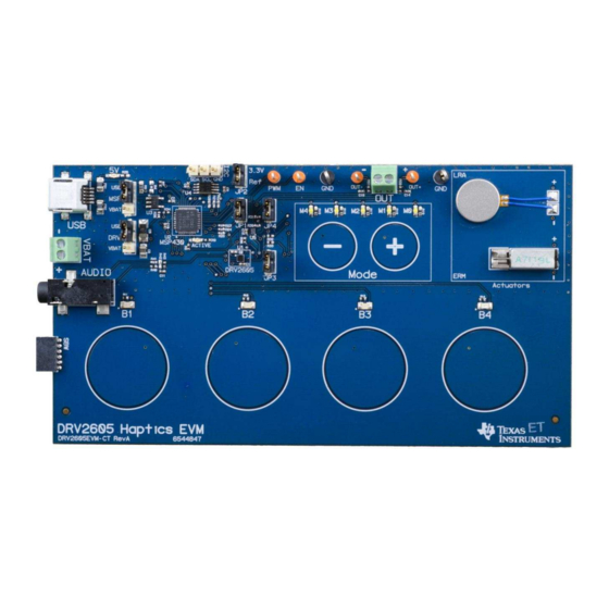
The DRV2605EVM-CT evaluation module (EVM) is a complete demo and evaluation platform for the
DRV2605. The kit includes a microcontroller, linear actuator, eccentric rotating mass motor, sample
waveforms, and capacitive touch buttons, which can completely demonstrate and evaluate the DRV2605.
This user's guide contains instructions to setup and operate the DRV2605EVM-CT in demonstration and
evaluation mode.
Evaluation Kit Contents:
•
DRV2605EVM-CT demo and evaluation board
•
Mini-USB cable
•
Demonstration mode firmware
Needed for programming and advanced configuration:
•
Code Composer Studio™ (CCS) or IAR Embedded Workbench IDE for MSP430
•
MSP430 LaunchPad (MSP-EXP430G2), or MSP430-FET430UIF hardware programming tool
•
DRV2605EVM-CT firmware available on
Code Composer Studio is a trademark of Texas Instruments.
All other trademarks are the property of their respective owners.
SLOU348B – January 2013 – Revised March 2014
Submit Documentation Feedback
www.ti.com
DRV2605EVM-CT ERM and LRA Haptic Driver Evaluation Kit
Copyright © 2013–2014, Texas Instruments Incorporated
SLOU348B – January 2013 – Revised March 2014
User's Guide
Kit
1
Advertisement
Table of Contents

Related Manuals for Texas Instruments DRV2605EVM-CT


Summary of Contents for Texas Instruments DRV2605EVM-CT
- Page 1 • Auto-resonance frequency tracking The DRV2605EVM-CT evaluation module (EVM) is a complete demo and evaluation platform for the DRV2605. The kit includes a microcontroller, linear actuator, eccentric rotating mass motor, sample waveforms, and capacitive touch buttons, which can completely demonstrate and evaluate the DRV2605.
-
Page 2: Table Of Contents
C Input ..................... Audio-to-Haptics Input ..................Terminal Block and Test Points ................... DRV2605 Unfiltered Waveform DRV2605EVM-CT ERM and LRA Haptic Driver Evaluation Kit SLOU348B – January 2013 – Revised March 2014 Submit Documentation Feedback Copyright © 2013–2014, Texas Instruments Incorporated... - Page 3 Mode and Effects Table ....................DRV2605 Library Table ....................Binary Counting Modes ......................Hardware Overview ......................MSP430 Pinout SLOU348B – January 2013 – Revised March 2014 DRV2605EVM-CT ERM and LRA Haptic Driver Evaluation Kit Submit Documentation Feedback Copyright © 2013–2014, Texas Instruments Incorporated...
-
Page 4: Getting Started
Getting Started The DRV2605 can be used as a demonstration or evaluation tool. When the DRV2605EVM-CT is powered on for the first time, a demo application automatically starts. To power the board, connect the DRV2605EVM-CT to an available USB port on your computer using the included mini-USB cable. The demo begins with a board power-up sequence, and then enters the demo effects mode. -
Page 5: Evaluation Module Operating Parameters
Select USB (5 V) or VBAT power for the DRV2605 2. Connect the included mini-USB cable to the USB connector on the DRV2605EVM-CT board. 3. Connect the other end of the USB cable to an available USB port on a computer, USB charger, or USB battery pack. -
Page 6: Drv2605 Demonstration Program
DRV2605 Demonstration Program The DRV2605EVM-CT contains a microcontroller and embedded software to control the DRV2605. There are three sets of modes accessible by pressing and holding the “+” button. Follow the instructions in the following sections to access the effects in each set. -
Page 7: Demo Mode
Demo Mode Table 2 lists the effects preloaded on the DRV2605EVM-CT. The modes are selected using the “+” and “–“ mode buttons in the center of the board. The current mode can be identified by the white LEDs directly above the mode buttons. Buttons B1 to B4 trigger the effects listed in the description column and change based on the selected mode. -
Page 8: Description Of The Demo Modes
Figure 5. ERM SharpClick_100 (Button 1) Figure 6. ERM StrongClick_60 and Release SharpClick_100 (Button 2) DRV2605EVM-CT ERM and LRA Haptic Driver Evaluation Kit SLOU348B – January 2013 – Revised March 2014 Submit Documentation Feedback Copyright © 2013–2014, Texas Instruments Incorporated... -
Page 9: Lra Sharptick2_80 (Button 1)
DRV2605. Figure 9. LRA Auto-Resonance On (Button 1) Figure 10. LRA Auto-Resonance Off (Button 2) SLOU348B – January 2013 – Revised March 2014 DRV2605EVM-CT ERM and LRA Haptic Driver Evaluation Kit Submit Documentation Feedback Copyright © 2013–2014, Texas Instruments Incorporated... -
Page 10: Lra Acceleration Versus Frequency Over Output Voltage
5. After each successfully repeated pattern, the board repeats the same pattern and adds one additional button effect to the sequence. DRV2605EVM-CT ERM and LRA Haptic Driver Evaluation Kit SLOU348B – January 2013 – Revised March 2014 Submit Documentation Feedback... -
Page 11: Erm Audio-To-Haptics Conversion (Button 1)
ERM and LRA. Figure 14. ERM Audio-to-Haptics Conversion Figure 15. LRA Audio-to-Haptics Conversion (Button 1) (Button 2) SLOU348B – January 2013 – Revised March 2014 DRV2605EVM-CT ERM and LRA Haptic Driver Evaluation Kit Submit Documentation Feedback Copyright © 2013–2014, Texas Instruments Incorporated... -
Page 12: Rom Library Mode
10 – 20 Library D 100 – 140 15 – 25 Library E >140 >30 DRV2605EVM-CT ERM and LRA Haptic Driver Evaluation Kit SLOU348B – January 2013 – Revised March 2014 Submit Documentation Feedback Copyright © 2013–2014, Texas Instruments Incorporated... -
Page 13: Rom Library Effects List
Transition ramp up long smooth 1 – 0 to Smooth hum 5 (No kick or brake pulse) – 10% 100% 100% SLOU348B – January 2013 – Revised March 2014 DRV2605EVM-CT ERM and LRA Haptic Driver Evaluation Kit Submit Documentation Feedback Copyright © 2013–2014, Texas Instruments Incorporated... -
Page 14: Additional Hardware Modes
Additional Hardware Modes Additional modes are available on the DRV2605EVM-CT that provide increased board control and functionality. The additional modes are not available in “demo” mode, but can be accessed by switching to “binary counting mode”. In “binary counting mode,” the mode LEDs count in binary (32 modes) rather than in “demo”... -
Page 15: Binary Counting Modes
About the board - the value appears on the mode LEDs in binary. About the board DRV2605 Device ID = 00011 Code revision LEDs: 11111 SLOU348B – January 2013 – Revised March 2014 DRV2605EVM-CT ERM and LRA Haptic Driver Evaluation Kit Submit Documentation Feedback Copyright © 2013–2014, Texas Instruments Incorporated... -
Page 16: Hardware Configuration
Hardware configuration details can be found in the following sections. Power Supply Selection The DRV2605EVM-CT can be powered by USB or an external power supply (VBAT). Jumpers “DRV” and “MSP” are used to select USB or VBAT for the DRV2605 and MSP430G2553, respectively. See the following table for possible configurations. -
Page 17: Using An External Actuator
From DRV2605 Figure 17. Terminal Block and Test Points The DRV2605EVM-CT can be used with an external actuator. Follow the instructions below to attach an actuator to the "OUT" terminal block. 1. Remove jumpers JP3 and JP4, which disconnects the on-board actuators from the DRV2605. -
Page 18: External Trigger Control
5. Select either external edge (2) or external level (3) trigger using button B3. The trigger type appears in binary on the mode LEDs. 6. Apply the trigger signal to the IN/TRIG pin by pressing button B4. DRV2605EVM-CT ERM and LRA Haptic Driver Evaluation Kit SLOU348B – January 2013 – Revised March 2014 Submit Documentation Feedback... -
Page 19: External I 2 C Input
“Active” LED. 4. Begin controlling the DRV2605 using the external I C source. SLOU348B – January 2013 – Revised March 2014 DRV2605EVM-CT ERM and LRA Haptic Driver Evaluation Kit Submit Documentation Feedback Copyright © 2013–2014, Texas Instruments Incorporated... -
Page 20: Audio-To-Haptics Input
The audio input minimum and maximum thresholds can be adjusted using I C. See the datasheet for more details. DRV2605EVM-CT ERM and LRA Haptic Driver Evaluation Kit SLOU348B – January 2013 – Revised March 2014 Submit Documentation Feedback Copyright © 2013–2014, Texas Instruments Incorporated... -
Page 21: Measurement And Analysis
Figure 23. DRV2605 Unfiltered Waveform Figure 24. DRV2605 Filtered Waveform If the DRV2605EVM-CT filter is not used, TI recommends using a first-order, low-pass filter with a cutoff between 1 and 3.5 kHz. Figure 25 shows a recommended output filter for use while measuring and characterizing the DRV2605 in the lab. -
Page 22: Msp430 Firmware
MSP430 Firmware The MSP430 firmware on the DRV2605EVM-CT can be modified or reprogrammed to create new haptic effects or behaviors. Find the latest firmware source code and binaries on www.ti.com. Follow these instructions to modify or reprogram the DRV2605EVM-CT: 1. -
Page 23: Msp430 Pinout
MSP430 Firmware www.ti.com MSP430 Pinout The DRV2605EVM-CT contains a MSP430G2553 low-cost microcontroller, which controls the board and contains sample haptic effects. The pinout for the microcontroller can be found in Table Table 6. MSP430 Pinout NAME DESCRIPTION P1.1 Green LED P1.2... -
Page 24: Schematic
0402 X7R 0402 0402 X5R µF / 6.3 V 0402 0402 SJ-3523-SMT 3.5 mm Audio-to-Haptics QFN32-RHB DRV2605EVM-CT ERM and LRA Haptic Driver Evaluation Kit SLOU348B – January 2013 – Revised March 2014 Submit Documentation Feedback Copyright © 2013–2014, Texas Instruments Incorporated... -
Page 25: Layout
Layout www.ti.com Layout Figure 27. X-Ray Top View spacer Figure 28. Top Copper SLOU348B – January 2013 – Revised March 2014 DRV2605EVM-CT ERM and LRA Haptic Driver Evaluation Kit Submit Documentation Feedback Copyright © 2013–2014, Texas Instruments Incorporated... -
Page 26: Layer 2 Copper
Layout www.ti.com Figure 29. Layer 2 Copper spacer Figure 30. Layer 3 Copper DRV2605EVM-CT ERM and LRA Haptic Driver Evaluation Kit SLOU348B – January 2013 – Revised March 2014 Submit Documentation Feedback Copyright © 2013–2014, Texas Instruments Incorporated... -
Page 27: Bottom Copper
Layout www.ti.com Figure 31. Bottom Copper SLOU348B – January 2013 – Revised March 2014 DRV2605EVM-CT ERM and LRA Haptic Driver Evaluation Kit Submit Documentation Feedback Copyright © 2013–2014, Texas Instruments Incorporated... -
Page 28: Bill Of Materials
SERIES ROHS RESISTORS ERJ-2RKF9761X P9.76KLCT-ND RESISTOR SMD0402 THICK FILM 9.76K PANASONIC OHMS 1/10W 1% ROHS DRV2605EVM-CT ERM and LRA Haptic Driver Evaluation Kit SLOU348B – January 2013 – Revised March 2014 Submit Documentation Feedback Copyright © 2013–2014, Texas Instruments Incorporated... - Page 29 ACUTATOR VIBRATION MOTOR 1,3V 9000 SANYO RPM ROHS SEMCO1030 ACTUATOR - LINEAR VIBRATOR, 2VRMS SAMSUNG SLOU348B – January 2013 – Revised March 2014 DRV2605EVM-CT ERM and LRA Haptic Driver Evaluation Kit Submit Documentation Feedback Copyright © 2013–2014, Texas Instruments Incorporated...
- Page 30 R0402_DNP PANASONIC R0402_DNP 541-0.0JCT R0402_DNP VISHAY This is an alternate actuator used on the EVM. DRV2605EVM-CT ERM and LRA Haptic Driver Evaluation Kit SLOU348B – January 2013 – Revised March 2014 Submit Documentation Feedback Copyright © 2013–2014, Texas Instruments Incorporated...
- Page 31 Changed item 40 to SEMCO1030 and added 40 (with note) as alternate actuator in BOM. NOTE: Page numbers for previous revisions may differ from page numbers in the current version. SLOU348B – January 2013 – Revised March 2014 Revision History Submit Documentation Feedback Copyright © 2013–2014, Texas Instruments Incorporated...
- Page 32 ADDITIONAL TERMS AND CONDITIONS, WARNINGS, RESTRICTIONS, AND DISCLAIMERS FOR EVALUATION MODULES Texas Instruments Incorporated (TI) markets, sells, and loans all evaluation boards, kits, and/or modules (EVMs) pursuant to, and user expressly acknowledges, represents, and agrees, and takes sole responsibility and risk with respect to, the following: 1.
- Page 33 RADIO FREQUENCY REGULATORY COMPLIANCE INFORMATION FOR EVALUATION MODULES Texas Instruments Incorporated (TI) evaluation boards, kits, and/or modules (EVMs) and/or accompanying hardware that is marketed, sold, or loaned to users may or may not be subject to radio frequency regulations in specific countries.
- Page 34 Les types d'antenne non inclus dans cette liste, ou dont le gain est supérieur au gain maximal indiqué, sont strictement interdits pour l'exploitation de l'émetteur. Mailing Address: Texas Instruments, Post Office Box 655303, Dallas, Texas 75265 Copyright © 2014, Texas Instruments Incorporated spacer Important Notice for Users of EVMs Considered “Radio Frequency Products”...
- Page 35 IMPORTANT NOTICE Texas Instruments Incorporated and its subsidiaries (TI) reserve the right to make corrections, enhancements, improvements and other changes to its semiconductor products and services per JESD46, latest issue, and to discontinue any product or service per JESD48, latest issue.
- Page 36 Mouser Electronics Authorized Distributor Click to View Pricing, Inventory, Delivery & Lifecycle Information: Texas Instruments DRV2605EVM-CT...
Need help?
Do you have a question about the DRV2605EVM-CT and is the answer not in the manual?
Questions and answers