Table of Contents
Advertisement
Quick Links
www.ti.com
User's Guide
DP83825 Evaluation Module
This user's guide details how to properly operate and configure the DP83825EVM.
1 Definitions...............................................................................................................................................................................
2
Introduction.............................................................................................................................................................................2
Features......................................................................................................................................................................2
Setup....................................................................................................................................................4
Options..........................................................................................................................................................6
3.1 Strap Options.....................................................................................................................................................................
4
Software...................................................................................................................................................................................7
Driver...................................................................................................................................................................7
4.2 USB2MDIO Software.........................................................................................................................................................
Details................................................................................................................................................................8
Diagram....................................................................................................................................................................8
5.2
Schematics.........................................................................................................................................................................9
6 Bill of Materials.....................................................................................................................................................................
7 Revision History...................................................................................................................................................................
Trademarks
Windows
®
is a registered trademark of Microsoft Corporation.
All trademarks are the property of their respective owners.
SNLU239A - DECEMBER 2018 - REVISED DECEMBER 2023
Submit Document Feedback
ABSTRACT
Table of Contents
Copyright © 2023 Texas Instruments Incorporated
Table of Contents
2
6
7
12
17
DP83825 Evaluation Module
1
Advertisement
Table of Contents

Related Manuals for Texas Instruments DP83825EVM


Summary of Contents for Texas Instruments DP83825EVM
-
Page 1: Table Of Contents
Table of Contents User's Guide DP83825 Evaluation Module ABSTRACT This user’s guide details how to properly operate and configure the DP83825EVM. Table of Contents 1 Definitions....................................Introduction.....................................2 2.1 Key Features..................................2 2.2 Operation – Quick Setup..............................4 3 Configurations Options................................6 3.1 Strap Options.................................. -
Page 2: Definitions
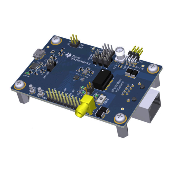
(RMII) both in Master and Slave mode. The 50 MHz clock in RMII Master mode is synchronized to MDI derived clock to improve the jitter in the system. The DP83825EVM demonstrates all features of DP83825 and supports 10BASE-Te and 100BASE-TX Ethernet protocols. - Page 3 Introduction Figure 2-1. DP83825EVM - Top Side Figure 2-2. DP83825EVM - Bottom Side SNLU239A – DECEMBER 2018 – REVISED DECEMBER 2023 DP83825 Evaluation Module Submit Document Feedback Copyright © 2023 Texas Instruments Incorporated...
-
Page 4: Operation - Quick Setup
On the VDD3V3, VDDIO, and MSP-IO connections, make sure that the jumpers are populated on position 1-2 for all three connectors shown in Figure 2-4. Figure 2-4. Supply Selection Jumpers - LDO DP83825 Evaluation Module SNLU239A – DECEMBER 2018 – REVISED DECEMBER 2023 Submit Document Feedback Copyright © 2023 Texas Instruments Incorporated... - Page 5 Introduction 2.2.3 External Supply DP83825EVM provides the option to power individual voltage rails from external power source giving customers more flexibility with EVM testing. ‘VDD3V3’, ‘VDDIO’, and ‘MSP-IO’ connectors shown above are used to switch individual rails from LDO source to External source. Connect jumper between pin 2-3 to switch from LDO supply to External power source.
-
Page 6: Configurations Options
PHY_AD[0] = 0 RX_D0 PHY_AD[0] PHY_AD[0] = 1 PHY_AD[1] = 0 CRS_DV PHY_AD[1] PHY_AD[1] = 1 AMDIX Enabled RX_ER AMDIX_DIS AMDIX Disabled DP83825 Evaluation Module SNLU239A – DECEMBER 2018 – REVISED DECEMBER 2023 Submit Document Feedback Copyright © 2023 Texas Instruments Incorporated... -
Page 7: Software
J10 connector. Customers can connect a MSP430 launchpad or their own MDIO-MDC utility on J10 to access the PHY registers. SNLU239A – DECEMBER 2018 – REVISED DECEMBER 2023 DP83825 Evaluation Module Submit Document Feedback Copyright © 2023 Texas Instruments Incorporated... -
Page 8: Board Setup Details
Resistors I/O 3.3V Clock-Out Connector MDIO DP83825 RESET 25MHz Clock in LEDs Diodes Magnetics RJ-45 Figure 5-1. DP83825EVM Block Diagram DP83825 Evaluation Module SNLU239A – DECEMBER 2018 – REVISED DECEMBER 2023 Submit Document Feedback Copyright © 2023 Texas Instruments Incorporated... -
Page 9: Schematics
VDDIO EARTH_GND RX_ER EARTH_GND 2.49k 22pF RX_D1 4700pF 2.49k EXT_REF_CLK RX_D0 EARTH_GND 2.49k CRS_DV 2.49k Figure 5-2. Schematic Page 1 SNLU239A – DECEMBER 2018 – REVISED DECEMBER 2023 DP83825 Evaluation Module Submit Document Feedback Copyright © 2023 Texas Instruments Incorporated... - Page 10 3V3_IO_LDO 3V3_IO_LDO VDDA3P3 VDDIO MCU_VCC VDDA3P3_EXT VDDIO_EXT MCU_VCC_EXT 5V-12V 5V-12V 22uF 10uF VDDIO_EXT MCU_VCC_EXT VDDA3P3_EXT Figure 5-3. Schematic Page 2 DP83825 Evaluation Module SNLU239A – DECEMBER 2018 – REVISED DECEMBER 2023 Submit Document Feedback Copyright © 2023 Texas Instruments Incorporated...
- Page 11 DVCC2 DVSS2 MCU_VCC MSP430F5529IPN RST/SBWTDIO 10uF 1000pF 0.1 µF 0.1 µF 0.1 µF TEST/SBWTCK RST/SBWTDIO Figure 5-4. Schematic Page 3 SNLU239A – DECEMBER 2018 – REVISED DECEMBER 2023 DP83825 Evaluation Module Submit Document Feedback Copyright © 2023 Texas Instruments Incorporated...
-
Page 12: Bill Of Materials
CAP, CERM, 10 pF, 50 V, +/- 5%, CGA3E2NP01H100D080AA C0G/NP0, 0603 C33, C36 0.22 uF CAP, CERM, 0.22 uF, 16 V, C0603C224Z4VACTU Kemet +80/-20%, Y5V, 0603 DP83825 Evaluation Module SNLU239A – DECEMBER 2018 – REVISED DECEMBER 2023 Submit Document Feedback Copyright © 2023 Texas Instruments Incorporated... - Page 13 ERJ-3GEY0R00V Panasonic Grade 0, 0603 100 kΩ RES, 100 k, 0.5%, 0.063 W, AEC- CRCW0402100KDHEDP Vishay-Dale Q200 Grade 0, 0402 SNLU239A – DECEMBER 2018 – REVISED DECEMBER 2023 DP83825 Evaluation Module Submit Document Feedback Copyright © 2023 Texas Instruments Incorporated...
- Page 14 RES, 47 k, 5%, 0.063 W, AEC- CRCW040247K0JNED Vishay-Dale Q200 Grade 0, 0402 Switch, Normally open, 2.3N force, KSR221GLFS C&K Components 200k operations, SMD DP83825 Evaluation Module SNLU239A – DECEMBER 2018 – REVISED DECEMBER 2023 Submit Document Feedback Copyright © 2023 Texas Instruments Incorporated...
- Page 15 Standoff, Hex, 0.5"L #4-40 Nylon Standoff 1902C Keystone JACK, SMA, 50 Ohm, Gold, R/A, SMA Jack, 50 5-1814400-1 TE Connectivity Ohm, R/A, TH SNLU239A – DECEMBER 2018 – REVISED DECEMBER 2023 DP83825 Evaluation Module Submit Document Feedback Copyright © 2023 Texas Instruments Incorporated...
- Page 16 1.00 MΩ RES, 1.00 M, 1%, 0.063 W, 0402 RC0402FR-071ML Yageo America R43, R45, R46, 0 Ω RES, 0, 5%, 0.05 W, 0201 CRCW02010000Z0ED Vishay-Dale R48, R50 DP83825 Evaluation Module SNLU239A – DECEMBER 2018 – REVISED DECEMBER 2023 Submit Document Feedback Copyright © 2023 Texas Instruments Incorporated...
-
Page 17: Revision History
Updated Supply Selection - LDO figure and clarified jumper configuration............5 • Added resistor names responsible for strapping the PHY..................6 • Added schematics.............................. • Added Bill of Materials table..........................SNLU239A – DECEMBER 2018 – REVISED DECEMBER 2023 DP83825 Evaluation Module Submit Document Feedback Copyright © 2023 Texas Instruments Incorporated... - Page 18 STANDARD TERMS FOR EVALUATION MODULES Delivery: TI delivers TI evaluation boards, kits, or modules, including any accompanying demonstration software, components, and/or documentation which may be provided together or separately (collectively, an “EVM” or “EVMs”) to the User (“User”) in accordance with the terms set forth herein.
- Page 19 www.ti.com Regulatory Notices: 3.1 United States 3.1.1 Notice applicable to EVMs not FCC-Approved: FCC NOTICE: This kit is designed to allow product developers to evaluate electronic components, circuitry, or software associated with the kit to determine whether to incorporate such items in a finished product and software developers to write software applications for use with the end product.
- Page 20 www.ti.com Concernant les EVMs avec antennes détachables Conformément à la réglementation d'Industrie Canada, le présent émetteur radio peut fonctionner avec une antenne d'un type et d'un gain maximal (ou inférieur) approuvé pour l'émetteur par Industrie Canada. Dans le but de réduire les risques de brouillage radioélectrique à...
- Page 21 www.ti.com EVM Use Restrictions and Warnings: 4.1 EVMS ARE NOT FOR USE IN FUNCTIONAL SAFETY AND/OR SAFETY CRITICAL EVALUATIONS, INCLUDING BUT NOT LIMITED TO EVALUATIONS OF LIFE SUPPORT APPLICATIONS. 4.2 User must read and apply the user guide and other available documentation provided by TI regarding the EVM prior to handling or using the EVM, including without limitation any warning or restriction notices.
- Page 22 Notwithstanding the foregoing, any judgment may be enforced in any United States or foreign court, and TI may seek injunctive relief in any United States or foreign court. Mailing Address: Texas Instruments, Post Office Box 655303, Dallas, Texas 75265 Copyright © 2023, Texas Instruments Incorporated...
- Page 23 TI products. TI’s provision of these resources does not expand or otherwise alter TI’s applicable warranties or warranty disclaimers for TI products. TI objects to and rejects any additional or different terms you may have proposed. IMPORTANT NOTICE Mailing Address: Texas Instruments, Post Office Box 655303, Dallas, Texas 75265 Copyright © 2023, Texas Instruments Incorporated...
Need help?
Do you have a question about the DP83825EVM and is the answer not in the manual?
Questions and answers