Table of Contents
Advertisement
Quick Links
www.ti.com
User's Guide
DP83561EVM User's Guide
Nikhil Menon
This User's Guide discusses how to properly operate and configure the DP83561EVM. For best layout practices,
schematic files, and Bill of Materials, see the associated sections and support documents.
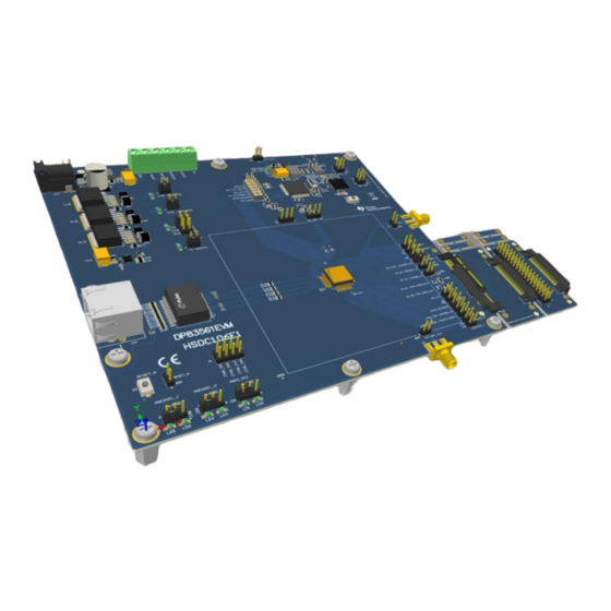
DP83561EVM consists of a main PCB and two breakout boards: DP83561-SP Ethernet board, MAC interface
breakout board, and MAC interface back-to-back connector.
Figure 1-1. DP83561EVM Main PCB and Two Breakout Boards
SLVUC11 – APRIL 2021
Submit Document Feedback
ABSTRACT
Copyright © 2021 Texas Instruments Incorporated
DP83561EVM User's Guide
1
Advertisement
Table of Contents

Related Manuals for Texas Instruments DP83561EVM


Summary of Contents for Texas Instruments DP83561EVM
-
Page 1: Figure 1-1. Dp83561Evm Main Pcb And Two Breakout Boards
Nikhil Menon ABSTRACT This User’s Guide discusses how to properly operate and configure the DP83561EVM. For best layout practices, schematic files, and Bill of Materials, see the associated sections and support documents. DP83561EVM consists of a main PCB and two breakout boards: DP83561-SP Ethernet board, MAC interface breakout board, and MAC interface back-to-back connector. -
Page 2: Table Of Contents
10 Bill of Materials................................... 11 REACH Compliance................................54 12 Revision History................................. List of Figures Figure 1-1. DP83561EVM Main PCB and Two Breakout Boards....................Figure 2-1. DP83561EVM – Top Side............................6 Figure 2-2. DP83561EVM – Bottom Side............................ Figure 2-3. DP83561EVM Block Diagram........................... Figure 2-4. Wide-Vin 5V-36V Supply Connection........................ - Page 3 Trademarks Figure 6-1. DP83561EVM SEFI Interrupt Pins.......................... Figure 8-1. DP83561EVM Main Power............................23 Figure 8-2. DP83561EVM Main Block............................Figure 8-3. DP83561EVM Bootstrap Settings........................... Figure 8-4. DP83561EVM AFE and MAC Interface........................26 Figure 8-5. DP83561EVM USB Hub............................27 Figure 8-6. DP83561EVM COMs 1............................
-
Page 4: Definitions
Media Independent Interface Start-of-Frame Detection VDDA Analog Core Supply Rail VDDIO Digital Supply Rail Pulldown Pullup Microcontroller Analog Front End SEFI Single Event Functional Interrupt DP83561EVM User’s Guide SLVUC11 – APRIL 2021 Submit Document Feedback Copyright © 2021 Texas Instruments Incorporated... -
Page 5: Introduction
Layer transceiver with integrated PMD sub-layers to support 10BASE-Te, 100BASE-TX and 1000BASE-T Ethernet protocols. The DP83561EVM is a tool used to highlight the features of the DP83561-SP Ethernet PHY. Breakout connectors are included to allow MAC access and back-to-back configuration support. The EVM also provides on-board tools to configure PHY registers using a USB-MDIO graphical user interface tool. -
Page 6: Figure 2-1. Dp83561Evm - Top Side
Introduction www.ti.com Figure 2-1. DP83561EVM – Top Side DP83561EVM User’s Guide SLVUC11 – APRIL 2021 Submit Document Feedback Copyright © 2021 Texas Instruments Incorporated... -
Page 7: Figure 2-2. Dp83561Evm - Bottom Side
Introduction Figure 2-2. DP83561EVM – Bottom Side SLVUC11 – APRIL 2021 DP83561EVM User’s Guide Submit Document Feedback Copyright © 2021 Texas Instruments Incorporated... -
Page 8: Block Diagram
Introduction www.ti.com 2.2 Block Diagram Figure 2-3. DP83561EVM Block Diagram DP83561EVM User’s Guide SLVUC11 – APRIL 2021 Submit Document Feedback Copyright © 2021 Texas Instruments Incorporated... -
Page 9: Operation - Quick Setup
2.3 Operation – Quick Setup The DP83561EVM can operate from a single Wide-Vin 5V-36V DC supply connected to the power jack J16 or the header J18. The DP83561-SP is configured for Dual Supply Mode by default. Due to RJ45 orientation and routing, Mirror Mode is enabled by default. -
Page 10: Figure 2-6. Dp83561Evm Mirror Mode Strap
Introduction www.ti.com Figure 2-6. DP83561EVM Mirror Mode Strap DP83561EVM User’s Guide SLVUC11 – APRIL 2021 Submit Document Feedback Copyright © 2021 Texas Instruments Incorporated... -
Page 11: Board Setup Details
The DP83561-SP can be powered by as few as two supplies in dual supply mode, or three supplies in triple supply mode. In dual supply mode, the VDDA1P8 pin must be left floating. By default the DP83561EVM is configured for dual supply mode. To configure the DP83561-SP in triple supply mode: •... -
Page 12: Configuration Options
• Connect micro-usb to J42 Note Only populate J21 when powering over USB. Figure 3-2. DP83561EVM USB Power Supply 3.2 Configuration Options 3.2.1 Bootstrap Options Some DP83561-SP configurations can be done through bootstrap options. Options can be selected with jumpers or resistor population. -
Page 13: Clock Selection
LED_2 ANEGSEL_1 3.2.2 Mirror Mode The DP83561EVM enables Mirror Mode by default. As can be observed in Section 8.4, due to the RJ45 orientation and routing on the board, the differential transmit and receive pairs orientation and polarity have been flipped on J27. -
Page 14: Mac Interface Breakout Connectors
MAC Interface Breakout Board Configuration The MAC Interface Breakout Board can be used to directly access the MII pins of the DP83561-SP. This board can be used for configurations such as configuring the DP83561EVM for RGMII external loopback tests as described by RGMII BER Testing - External Loopback Configuration, or connecting an MII MAC. -
Page 15: Led Indication
– By default, LED0 indicates valid link established. – By default, LED1 indicates 1000Base-T link established – By default, LED2 indicates RX/TX activity 3.6 Serial Management Interface The DP83561EVM supports SMI (MDIO/MDC) through J43 and includes an on-board MSP for USB-2-MDIO control. Notes: •... -
Page 16: Ber Testing
Analog Loopback for the BER test. In this case, Link Partner A will send data across the cable to DP83561EVM A, to be sent across the RGMII interface to DP83561EVM B, looped back to DP83561EVM A, and received by Link Partner A. Please note, that in Analog Loopback, the MDI output pairs must have a 100 ohm differential termination. -
Page 17: Figure 4-2. Dp83561Evm Ber Testing Mii Connection Diagram
For additional information on configuring loopback modes, please refer to the device data sheet. Link Partner DP83561EVM MII MAC Cable Interface Breakout Figure 4-2. DP83561EVM BER Testing MII Connection Diagram SLVUC11 – APRIL 2021 DP83561EVM User’s Guide Submit Document Feedback Copyright © 2021 Texas Instruments Incorporated... -
Page 18: Compliance Testing
5 Compliance Testing The DP83561EVM supports IEEE 802.3 Ethernet Compliance testing, providing an option to connect a test fixture via an RJ45 connector on J16. Please refer to the device datasheet for details on setting the different Ethernet Compliance Test Modes. -
Page 19: Sefi Support Monitoring
PHY when a SEFI is detected. Please refer to the device datasheet for detailed descriptions of each function. This section describes how to observe each interrupt using the DP83561EVM. The DP83561EVM has hooks to observe the following SEFI events: •... - Page 20 R44 respectively may be replaced with a 2.2k resistor and connected to VDDIO. VDDIO can be accessed via pins 2, 4, and 6 of header P2. DP83561EVM User’s Guide SLVUC11 – APRIL 2021 Submit Document Feedback Copyright © 2021 Texas Instruments Incorporated...
-
Page 21: Software
USB-2-MDIO software can be used for accessing the PHY's registers. In the case where an external MSP430 or ezFET is needed, the user may simply connect the TST and RST pins of their device to the DP83561EVM. 7.1 MSP430 Driver Install the latest MSP430 driver from this website: http://software-dl.ti.com/msp430/msp430_public_sw/mcu/... -
Page 22: Schematics
Schematics www.ti.com 8 Schematics DP83561EVM User’s Guide SLVUC11 – APRIL 2021 Submit Document Feedback Copyright © 2021 Texas Instruments Incorporated... -
Page 23: Main Power Schematic
Green Green Green Green TPS74701DRCR 4.99k R108 27pF R109 R110 R111 DNBT8105-7 2.49k DNBT8105-7 DNBT8105-7 DNBT8105-7 2.49k 2.49k 2.49k Figure 8-1. DP83561EVM Main Power SLVUC11 – APRIL 2021 DP83561EVM User’s Guide Submit Document Feedback Copyright © 2021 Texas Instruments Incorporated... -
Page 24: Main Block Schematic
JTAG_TMS DP83561HBE-EM 2.2k JTAG_TMS JTAG_TDO JTAG_CLK 2.2k JTAG_TDO JTAG_TDI JTAG_TDI VDDIO 2.2k 2.2k CMP-0075408-3 JTAG_CLK INT_PWDN 6.04k CMP-0075407-2 6.04k Figure 8-2. DP83561EVM Main Block DP83561EVM User’s Guide SLVUC11 – APRIL 2021 Submit Document Feedback Copyright © 2021 Texas Instruments Incorporated... -
Page 25: Bootstrap Settings Schematic
VDDIO CMP-0075405-2 2.49k R168 2.49k CMP-0002917-2 Green R173 LED2 LED 0 CMP-0075405-2 2.49k CMP-0075407-2 R170 R171 2.49k CMP-0002917-2 Green Figure 8-3. DP83561EVM Bootstrap Settings SLVUC11 – APRIL 2021 DP83561EVM User’s Guide Submit Document Feedback Copyright © 2021 Texas Instruments Incorporated... -
Page 26: Analog Front End And Mac Interface Schematic
TP10 RJ45_ERTH COL_CS CRS_CS TP_H0.45P0.75 TP_H0.45P0.75 TP_H0.45P0.75 TP_H0.45P0.75 TP_H0.45P0.75 TP_H0.45P0.75 TP_H0.45P0.75 TP_H0.45P0.75 TP_H0.45P0.75 TP_H0.45P0.75 RESET_N RESETN_CS ERM8-030-01-L-D-EM2-TR Figure 8-4. DP83561EVM AFE and MAC Interface DP83561EVM User’s Guide SLVUC11 – APRIL 2021 Submit Document Feedback Copyright © 2021 Texas Instruments Incorporated... -
Page 27: Usb Hub Schematic
BUSPWR R199 HUB_D2_P RESET R200 C126 1.00M C127 C128 XTAL1 XTAL2 MCU_VCC 10pF 10pF 0.1µF 6MHz TUSB2046BIRHBT C129 0.1µF Figure 8-5. DP83561EVM USB Hub SLVUC11 – APRIL 2021 DP83561EVM User’s Guide Submit Document Feedback Copyright © 2021 Texas Instruments Incorporated... -
Page 28: Coms 1 Schematic
0.22uF AVSS1 1.00M AVCC1 AVSS2 DVCC1 DVSS1 DVCC2 DVSS2 MCU_VCC MSP430F5529IPN TEST/SBWTCK RST/SBWTDIO RST/SBWTDIO 10uF 0.1µF 0.1µF 0.1µF 1000pF Figure 8-6. DP83561EVM COMs 1 DP83561EVM User’s Guide SLVUC11 – APRIL 2021 Submit Document Feedback Copyright © 2021 Texas Instruments Incorporated... -
Page 29: Coms 2 Schematic
EZFET_VUSB 1000pF EZFET_SBW_RST RST/SBWTDIO VUSB VSSU 0.22µF AVSS1 MCU_VCC AVCC1 AVSS2 DVCC1 DVSS1 DVCC2 DVSS2 MSP430F5528IRGCR 0.1µF 10uF 0.1µF Figure 8-7. DP83561EVM COMs 2 SLVUC11 – APRIL 2021 DP83561EVM User’s Guide Submit Document Feedback Copyright © 2021 Texas Instruments Incorporated... -
Page 30: Breakout Boards Schematic
GTX_CLK_1 GTX_CLK_1 MDC_1 TX_D3_1 MDIO_1 TX_D2_1 RX_ER_1 TX_D1_1 TX_D0_1 TSW-118-07-G-D TX_CTRL_1 GND_1 COL_1 CRS_1 GND_1 RESETN_1 GND_1 ERF8-030-01-L-D-EM2-TR GND_1 Figure 8-8. DP83561EVM Breakout Connectors DP83561EVM User’s Guide SLVUC11 – APRIL 2021 Submit Document Feedback Copyright © 2021 Texas Instruments Incorporated... -
Page 31: Hardware Schematic
These assemblies must be clean and free from flux and all contaminants. Use of no clean flux is not acceptable. Assembly Note These assemblies must comply with workmanship standards IPC-A-610 Class 2, unless otherwise specified. Figure 8-9. DP83561EVM Hardware SLVUC11 – APRIL 2021 DP83561EVM User’s Guide Submit Document Feedback Copyright © 2021 Texas Instruments Incorporated... -
Page 32: Layout
Layout www.ti.com 9 Layout 9.1 Top Overlay Figure 9-1. Top Overlay DP83561EVM User’s Guide SLVUC11 – APRIL 2021 Submit Document Feedback Copyright © 2021 Texas Instruments Incorporated... -
Page 33: Top Layer Mask
Layout 9.2 Top Layer Mask Figure 9-2. Top Layer Mask SLVUC11 – APRIL 2021 DP83561EVM User’s Guide Submit Document Feedback Copyright © 2021 Texas Instruments Incorporated... -
Page 34: Top Layer
Layout www.ti.com 9.3 Top Layer Figure 9-3. Top Layer DP83561EVM User’s Guide SLVUC11 – APRIL 2021 Submit Document Feedback Copyright © 2021 Texas Instruments Incorporated... -
Page 35: Ground Layer 1
Layout 9.4 Ground Layer 1 Figure 9-4. Ground Layer 1 SLVUC11 – APRIL 2021 DP83561EVM User’s Guide Submit Document Feedback Copyright © 2021 Texas Instruments Incorporated... -
Page 36: Signal Layer 1
Layout www.ti.com 9.5 Signal Layer 1 Figure 9-5. Signal Layer 1 DP83561EVM User’s Guide SLVUC11 – APRIL 2021 Submit Document Feedback Copyright © 2021 Texas Instruments Incorporated... -
Page 37: Signal Layer 2
Layout 9.6 Signal Layer 2 Figure 9-6. Signal Layer 2 SLVUC11 – APRIL 2021 DP83561EVM User’s Guide Submit Document Feedback Copyright © 2021 Texas Instruments Incorporated... -
Page 38: Ground Layer 2
Layout www.ti.com 9.7 Ground Layer 2 Figure 9-7. Ground Layer 2 DP83561EVM User’s Guide SLVUC11 – APRIL 2021 Submit Document Feedback Copyright © 2021 Texas Instruments Incorporated... -
Page 39: Bottom Layer
Layout 9.8 Bottom Layer Figure 9-8. Bottom Layer SLVUC11 – APRIL 2021 DP83561EVM User’s Guide Submit Document Feedback Copyright © 2021 Texas Instruments Incorporated... -
Page 40: Bottom Layer Mask
Layout www.ti.com 9.9 Bottom Layer Mask Figure 9-9. Bottom Layer Mask DP83561EVM User’s Guide SLVUC11 – APRIL 2021 Submit Document Feedback Copyright © 2021 Texas Instruments Incorporated... -
Page 41: Bottom Overlay
Layout 9.10 Bottom Overlay Figure 9-10. Bottom Overlay SLVUC11 – APRIL 2021 DP83561EVM User’s Guide Submit Document Feedback Copyright © 2021 Texas Instruments Incorporated... -
Page 42: Board Assembly
Layout www.ti.com 9.11 Board Assembly Figure 9-11. Top Assembly DP83561EVM User’s Guide SLVUC11 – APRIL 2021 Submit Document Feedback Copyright © 2021 Texas Instruments Incorporated... -
Page 43: Figure 9-12. Bottom Assembly
Layout Figure 9-12. Bottom Assembly SLVUC11 – APRIL 2021 DP83561EVM User’s Guide Submit Document Feedback Copyright © 2021 Texas Instruments Incorporated... -
Page 44: Figure 9-13. Drill Drawing
Layout www.ti.com Figure 9-13. Drill Drawing DP83561EVM User’s Guide SLVUC11 – APRIL 2021 Submit Document Feedback Copyright © 2021 Texas Instruments Incorporated... -
Page 45: Figure 9-14. Board Dimensions
Layout Figure 9-14. Board Dimensions SLVUC11 – APRIL 2021 DP83561EVM User’s Guide Submit Document Feedback Copyright © 2021 Texas Instruments Incorporated... -
Page 46: Bill Of Materials
Mechanics C50, C52, C68, 10uF CAP, CERM, 10 uF, 25 V, +/- 20%, X7R, AEC- 1210 CGA6P1X7R1E106M250AC C70, C78, C80 Q200 Grade 1, 1210 DP83561EVM User’s Guide SLVUC11 – APRIL 2021 Submit Document Feedback Copyright © 2021 Texas Instruments Incorporated... - Page 47 CAP, CERM, 470 pF, 100 V, +/- 5%, X7R, 0603 0603 06031C471JAT2A C116 4.7uF CAP, TA, 4.7 uF, 35 V, +/- 10%, 1.3 ohm, SMD 7343-31 293D475X9035D2TE3 Vishay-Sprague SLVUC11 – APRIL 2021 DP83561EVM User’s Guide Submit Document Feedback Copyright © 2021 Texas Instruments Incorporated...
- Page 48 J15, J28, J33, J38, Header, 100mil, 3x1, Gold, TH 3x1 Header TSW-103-07-G-S Samtec DC POWER JACK, R/A, TH DC POWER JACK, PJ-002AH CUI Inc. R/A, TH DP83561EVM User’s Guide SLVUC11 – APRIL 2021 Submit Document Feedback Copyright © 2021 Texas Instruments Incorporated...
- Page 49 RES, 0, 5%, 0.063 W, 0402 0402 RC0402JR-070RL Yageo America R8, R75, R198 RES, 47 k, 5%, 0.063 W, AEC-Q200 Grade 0, 0402 CRCW040247K0JNED Vishay-Dale 0402 SLVUC11 – APRIL 2021 DP83561EVM User’s Guide Submit Document Feedback Copyright © 2021 Texas Instruments Incorporated...
- Page 50 RES, 1.00 M, 1%, 0.063 W, AEC-Q200 Grade 0402 CRCW04021M00FKED Vishay-Dale 0, 0402 RES, 100, 5%, 0.1 W, AEC-Q200 Grade 0, 0402 ERJ-2GEJ101X Panasonic 0402 DP83561EVM User’s Guide SLVUC11 – APRIL 2021 Submit Document Feedback Copyright © 2021 Texas Instruments Incorporated...
- Page 51 RES, 27, 5%, 0.063 W, AEC-Q200 Grade 0, 0402 CRCW040227R0JNED Vishay-Dale R199 0402 R181, R182, R184, RES, 22, 5%, 0.063 W, AEC-Q200 Grade 0, 0402 CRCW040222R0JNED Vishay-Dale R185, R192, R193 0402 SLVUC11 – APRIL 2021 DP83561EVM User’s Guide Submit Document Feedback Copyright © 2021 Texas Instruments Incorporated...
- Page 52 ABM3 ABM3-25.000MHZ-D2Y-T Abracon Corporation Oscillator, 4 MHz, 700 ppm, 39 pF, SMD 4.5x2mm CSTNR4M00GH5L000R0 MuRata Crystal, 24 MHz, 20pF, SMD 3.2x2.5mm ECS-240-20-33-DU-TR ECS Inc. DP83561EVM User’s Guide SLVUC11 – APRIL 2021 Submit Document Feedback Copyright © 2021 Texas Instruments Incorporated...
- Page 53 350µH LAN 10/100/1000 Base-T Pulse SMD24 1000B-5001X Pulse Electronics Transformer 1:1 Surface Mount U11, U12 4-Channel Ultra-Low-Capacitance IEC ESD DQA0010A TPD4E05U06DQAR Texas Instruments Protection Diode, DQA0010A (USON-10) SLVUC11 – APRIL 2021 DP83561EVM User’s Guide Submit Document Feedback Copyright © 2021 Texas Instruments Incorporated...
-
Page 54: Reach Compliance
In compliance with the Article 33 provision of the EU REACH regulation we are notifying you that this EVM includes component(s) containing at least one Substance of Very High Concern (SVHC) above 0.1%. These uses from Texas Instruments do not exceed 1 ton per year. The SVHC’s are found in Table 11-1: Table 11-1. - Page 55 STANDARD TERMS FOR EVALUATION MODULES Delivery: TI delivers TI evaluation boards, kits, or modules, including any accompanying demonstration software, components, and/or documentation which may be provided together or separately (collectively, an “EVM” or “EVMs”) to the User (“User”) in accordance with the terms set forth herein.
- Page 56 www.ti.com Regulatory Notices: 3.1 United States 3.1.1 Notice applicable to EVMs not FCC-Approved: FCC NOTICE: This kit is designed to allow product developers to evaluate electronic components, circuitry, or software associated with the kit to determine whether to incorporate such items in a finished product and software developers to write software applications for use with the end product.
- Page 57 www.ti.com Concernant les EVMs avec antennes détachables Conformément à la réglementation d'Industrie Canada, le présent émetteur radio peut fonctionner avec une antenne d'un type et d'un gain maximal (ou inférieur) approuvé pour l'émetteur par Industrie Canada. Dans le but de réduire les risques de brouillage radioélectrique à...
- Page 58 www.ti.com EVM Use Restrictions and Warnings: 4.1 EVMS ARE NOT FOR USE IN FUNCTIONAL SAFETY AND/OR SAFETY CRITICAL EVALUATIONS, INCLUDING BUT NOT LIMITED TO EVALUATIONS OF LIFE SUPPORT APPLICATIONS. 4.2 User must read and apply the user guide and other available documentation provided by TI regarding the EVM prior to handling or using the EVM, including without limitation any warning or restriction notices.
- Page 59 Notwithstanding the foregoing, any judgment may be enforced in any United States or foreign court, and TI may seek injunctive relief in any United States or foreign court. Mailing Address: Texas Instruments, Post Office Box 655303, Dallas, Texas 75265 Copyright © 2019, Texas Instruments Incorporated...
- Page 60 TI products. TI’s provision of these resources does not expand or otherwise alter TI’s applicable warranties or warranty disclaimers for TI products.IMPORTANT NOTICE Mailing Address: Texas Instruments, Post Office Box 655303, Dallas, Texas 75265 Copyright © 2021, Texas Instruments Incorporated...
Need help?
Do you have a question about the DP83561EVM and is the answer not in the manual?
Questions and answers