Table of Contents
Advertisement
Quick Links
www.ti.com
User's Guide
DP83TG721EVM-MC User Guide
This User's Guide discusses how to properly operate and configure the DP83TG721 Media Converter EVM. For
layout, schematic files, and Bill of Materials, see the DP83TG721 product page.
SNLU321 – JANUARY 2023
Submit Document Feedback
ABSTRACT
DP83TG721EVM-MC
Copyright © 2023 Texas Instruments Incorporated
DP83TG721EVM-MC User Guide
1
Advertisement
Table of Contents

Related Manuals for Texas Instruments DP83TG721EVM-MC


Summary of Contents for Texas Instruments DP83TG721EVM-MC
- Page 1 This User’s Guide discusses how to properly operate and configure the DP83TG721 Media Converter EVM. For layout, schematic files, and Bill of Materials, see the DP83TG721 product page. DP83TG721EVM-MC SNLU321 – JANUARY 2023 DP83TG721EVM-MC User Guide Submit Document Feedback Copyright © 2023 Texas Instruments Incorporated...
-
Page 2: Table Of Contents
Configuration................................12 3.8 MDI Connection................................4 Schematic, Board Layout, and Bill of Materials.........................14 4.1 Schematic..................................Trademarks All trademarks are the property of their respective owners. DP83TG721EVM-MC User Guide SNLU321 – JANUARY 2023 Submit Document Feedback Copyright © 2023 Texas Instruments Incorporated... -
Page 3: Introduction
Introduction 1 Introduction The DP83TG721EVM-MC supports 1000 Mbps speed and is IEEE 802.3bp compliant. There is an on-board MSP430F5529 for use with the USB2MDIO graphical user interface tool. The DP83867 is provided for copper (1000BASE-T) support using the RGMII MAC Interface. -
Page 4: Board Connections
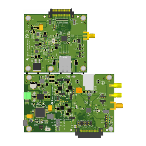
Introduction www.ti.com 1.2 Board Connections Figure 1-2. Board Connections DP83TG721EVM-MC User Guide SNLU321 – JANUARY 2023 Submit Document Feedback Copyright © 2023 Texas Instruments Incorporated... - Page 5 Micro-USB for power and data 60 pin media conversion connector Reset button SMA MDI connection for DP83TG721 External clock-in for DP83TG721 DP83867 CLKOUT DP83TG721 CLKOUT Break-here line SNLU321 – JANUARY 2023 DP83TG721EVM-MC User Guide Submit Document Feedback Copyright © 2023 Texas Instruments Incorporated...
-
Page 6: Operation - Quick Start
6. The board is now ready to connect to a link partner. If you wish, perform steps 1-5 on an additional DP83TG721EVM-MC and connect the boards together using an automotive Ethernet cable with MATEnet connectors. a. Ensure that master/slave selection is configured appropriately (Through register write or bootstrap). -
Page 7: Further Configuration
The EVM can be powered directly through the micro-USB port. • Alternately, connect 5-20V to TP7 and GND to TP8, or use the terminal block J28. Figure 3-1. Power Supply Connection SNLU321 – JANUARY 2023 DP83TG721EVM-MC User Guide Submit Document Feedback Copyright © 2023 Texas Instruments Incorporated... -
Page 8: Msp Connection
Master Mode: Place shunt across pins 2 and 3 of J12. • Slave Mode: Place shunt across pins 1 and 2 of J12. Figure 3-3. Master/Slave Jumper DP83TG721EVM-MC User Guide SNLU321 – JANUARY 2023 Submit Document Feedback Copyright © 2023 Texas Instruments Incorporated... -
Page 9: Wake Selection
Wake High: Place shunt across pins 1 and 2 of J4. • Wake Low: Place shunt across pin 2 of J4 and J7. Figure 3-4. Wake Jumper SNLU321 – JANUARY 2023 DP83TG721EVM-MC User Guide Submit Document Feedback Copyright © 2023 Texas Instruments Incorporated... -
Page 10: Autonomous/Managed Mode Selection
(<0x018C> = 0x0001). To select the mode, place a shunt on header J5 in the position indicated in Figure 3-5. Figure 3-5. Autonomous/Managed Mode Selection DP83TG721EVM-MC User Guide SNLU321 – JANUARY 2023 Submit Document Feedback Copyright © 2023 Texas Instruments Incorporated... -
Page 11: Led Indication
LED_1 (LD1 or LD2) will blink for TX/RX activity. • LEDs on the RJ45 connector will illuminate when a link is successfully established on the DP83867. Figure 3-6. LED Indicators SNLU321 – JANUARY 2023 DP83TG721EVM-MC User Guide Submit Document Feedback Copyright © 2023 Texas Instruments Incorporated... -
Page 12: Clock Configuration
– Remove R60 and R61. – Populate R56 with a 0 ohm resistor. – Connect external clock source to J16. Figure 3-7. Clock Reference DP83TG721EVM-MC User Guide SNLU321 – JANUARY 2023 Submit Document Feedback Copyright © 2023 Texas Instruments Incorporated... -
Page 13: Mdi Connection
If desired, these signals can be routed to SMA connectors instead. The steps to do this follow: 1. Remove R39, R42. 2. Place 0 ohm resistors on R35, R46. Figure 3-8. MDI Connection Selection SNLU321 – JANUARY 2023 DP83TG721EVM-MC User Guide Submit Document Feedback Copyright © 2023 Texas Instruments Incorporated... - Page 14 4 Schematic, Board Layout, and Bill of Materials These files can be found on the DP83TG721 product page under "Design Files". Schematics are also shown below. DP83TG721EVM-MC User Guide SNLU321 – JANUARY 2023 Submit Document Feedback Copyright © 2023 Texas Instruments Incorporated...
- Page 15 1.00k 1.00k 1µF 0.1uF 0.1uF 0.047uF STRP_1 901-144-8RFX STRP_1 TRD5_P DP83TG721S-Q1 100k 4700pF Supply Decoupling DP83TG721 SMA MC CLKOUT Figure 4-1. Schematic : DP83TG721 SNLU321 – JANUARY 2023 DP83TG721EVM-MC User Guide Submit Document Feedback Copyright © 2023 Texas Instruments Incorporated...
- Page 16 REV_SEL_2 REV_SEL_3 2200pF GND_MSP 3V3_MSP GND_MSP GND_MSP GND_MSP GND_MSP 2.2k 2.2k 2.2k 2.2k RESET SOFTWARE REV. GND_MSP DIP Switch Figure 4-2. Schematic : MSP430 DP83TG721EVM-MC User Guide SNLU321 – JANUARY 2023 Submit Document Feedback Copyright © 2023 Texas Instruments Incorporated...
- Page 17 These assemblies must comply with workmanship standards IPC-A-610 Class 2, unless otherwise speci e d. ¤ Figure 4-3. Schematic : MSP430 Reset and Wake SNLU321 – JANUARY 2023 DP83TG721EVM-MC User Guide Submit Document Feedback Copyright © 2023 Texas Instruments Incorporated...
- Page 18 2.49k VDDIO VDDA VSLEEP RX_D0 3V3_MSP RX_D1 RX_D2_RX_P RX_D3_RX_M Green Green Green Green Green Power Indica ¡ Figure 4-4. Schematic : Power and Straps DP83TG721EVM-MC User Guide SNLU321 – JANUARY 2023 Submit Document Feedback Copyright © 2023 Texas Instruments Incorporated...
- Page 19 GND_H VDDIO_H GND_H GND_H 100nF C17_1 C18_1 C71_1 C72_1 GND_H GND_H GND_H GND_H 100nF 100nF GND_H GND_H GND_H GND_H Figure 4-5. Schematic : DP83867 SNLU321 – JANUARY 2023 DP83TG721EVM-MC User Guide Submit Document Feedback Copyright © 2023 Texas Instruments Incorporated...
- Page 20 3V3_H 1V0_H R231_1 Q5_1 27pF DNBT8105-7 DNBT8105-7 DNBT8105-7 2.49k 2.49k 2.49k DNBT8105-7 2.49k GND_H GND_H GND_H GND_H GND_H Figure 4-6. Schematic : DP83867 Power DP83TG721EVM-MC User Guide SNLU321 – JANUARY 2023 Submit Document Feedback Copyright © 2023 Texas Instruments Incorporated...
- Page 21 All 60 pin connector need alignment slot. Please Ensure the slot is provided on the board. GND_H ERM8-030-01-L-D-EM2-TR GND_H GND_H Figure 4-7. Schematic : DP83867 RJ45 SNLU321 – JANUARY 2023 DP83TG721EVM-MC User Guide Submit Document Feedback Copyright © 2023 Texas Instruments Incorporated...
- Page 22 STANDARD TERMS FOR EVALUATION MODULES Delivery: TI delivers TI evaluation boards, kits, or modules, including any accompanying demonstration software, components, and/or documentation which may be provided together or separately (collectively, an “EVM” or “EVMs”) to the User (“User”) in accordance with the terms set forth herein.
- Page 23 www.ti.com Regulatory Notices: 3.1 United States 3.1.1 Notice applicable to EVMs not FCC-Approved: FCC NOTICE: This kit is designed to allow product developers to evaluate electronic components, circuitry, or software associated with the kit to determine whether to incorporate such items in a finished product and software developers to write software applications for use with the end product.
- Page 24 www.ti.com Concernant les EVMs avec antennes détachables Conformément à la réglementation d'Industrie Canada, le présent émetteur radio peut fonctionner avec une antenne d'un type et d'un gain maximal (ou inférieur) approuvé pour l'émetteur par Industrie Canada. Dans le but de réduire les risques de brouillage radioélectrique à...
- Page 25 www.ti.com EVM Use Restrictions and Warnings: 4.1 EVMS ARE NOT FOR USE IN FUNCTIONAL SAFETY AND/OR SAFETY CRITICAL EVALUATIONS, INCLUDING BUT NOT LIMITED TO EVALUATIONS OF LIFE SUPPORT APPLICATIONS. 4.2 User must read and apply the user guide and other available documentation provided by TI regarding the EVM prior to handling or using the EVM, including without limitation any warning or restriction notices.
- Page 26 Notwithstanding the foregoing, any judgment may be enforced in any United States or foreign court, and TI may seek injunctive relief in any United States or foreign court. Mailing Address: Texas Instruments, Post Office Box 655303, Dallas, Texas 75265 Copyright © 2023, Texas Instruments Incorporated...
- Page 27 TI products. TI’s provision of these resources does not expand or otherwise alter TI’s applicable warranties or warranty disclaimers for TI products. TI objects to and rejects any additional or different terms you may have proposed. IMPORTANT NOTICE Mailing Address: Texas Instruments, Post Office Box 655303, Dallas, Texas 75265 Copyright © 2023, Texas Instruments Incorporated...
Need help?
Do you have a question about the DP83TG721EVM-MC and is the answer not in the manual?
Questions and answers