Table of Contents
Advertisement
Quick Links
www.ti.com
User's Guide
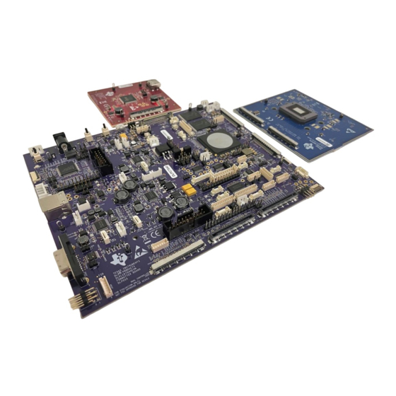
DLP® Display DLPC7540 4K UHD EVM
This guide explains the hardware and software features of the DLP
and DLPC7540EVM evaluation modules (EVMs). The EVM architecture and connectors will be described
along with a quick start guide on how to operate the DLP471TEEVM, DPL650TEEVM, and DLPC7540EVM
EVMs using the DLPDLC-GUI. Specific DLP chip details and operation can be found in related component
documentation.
Power supply, optics, illumination source, and cables are not included. See
Operation.
Figure 1-1. DLP Products DLPC7540EVM and DLP471TEEVM Evaluation Modules
DLPU109 – MAY 2021
Submit Document Feedback
ABSTRACT
Note
Copyright © 2021 Texas Instruments Incorporated
®
Products DLP471TEEVM, DPL650TEEVM,
Other Items Needed for
DLP® Display DLPC7540 4K UHD EVM
1
Advertisement
Table of Contents

Subscribe to Our Youtube Channel
Related Manuals for Texas Instruments DLP471TEEVM


Summary of Contents for Texas Instruments DLP471TEEVM
-
Page 1: Figure 1-1. Dlp Products Dlpc7540Evm And Dlp471Teevm Evaluation Modules
DLPC7540EVM evaluation modules (EVMs). The EVM architecture and connectors will be described along with a quick start guide on how to operate the DLP471TEEVM, DPL650TEEVM, and DLPC7540EVM EVMs using the DLPDLC-GUI. Specific DLP chip details and operation can be found in related component documentation. -
Page 2: Table Of Contents
Table of Contents 1 DLPC7540EVM, DLP471TEEVM, and DLP650TEEVM Overview..................3 1.1 Welcome.................................... 1.2 What is in the DLP471TEEVM, DLP650TEEVM, and DLPC7540EVM Evaluation Modules?...........3 1.3 EVM Boards..................................1.4 Other Items Needed for Operation.............................6 1.5 DLPC7540EVM, DLP471TEEVM, and DLP650TEEVM EVM Flex Cable................. -
Page 3: Dlpc7540Evm, Dlp471Teevm, And Dlp650Teevm Overview
Stage Lighting Systems 1.2 What is in the DLP471TEEVM, DLP650TEEVM, and DLPC7540EVM Evaluation Modules? The DLP471TEEVM, DLP650TEEVM and DLPC7540EVM are designed to be used in pairs. The DMD EVMs cannot be operated without the Controller EVM, DLPC7540EVM. The DLP471TEEVM, which includes the DLP471TE display chip, and the DLP650TEEVM, which includes the DLP650TE display chip, include the two flex cables required to connect to the DLPC7540EVM. -
Page 4: Figure 1-2. Dlpc7540Evm Front-End Board
DLPC7540EVM, DLP471TEEVM, and DLP650TEEVM Overview www.ti.com Figure 1-2. DLPC7540EVM Front-end Board Figure 1-3. DLP471TEEVM DLP® Display DLPC7540 4K UHD EVM DLPU109 – MAY 2021 Submit Document Feedback Copyright © 2021 Texas Instruments Incorporated... -
Page 5: Evm Boards
DLPC7540EVM, DLP471TEEVM, and DLP650TEEVM Overview 1.3 EVM Boards The DLP471TEEVM, DLP650TEEVM, and DLPC7540EVM EVMs contain the electronics required to drive either DLP471TE or DLP650TE DMD. The DLPC7540EVM offers several interface options for USB, I2C, and trigger inputs and outputs. -
Page 6: Other Items Needed For Operation
The firmware provided on ti.com is for the sole purpose of operating the electronic components that make up the DLP471TEEVM, DLP650TEEVM, and the DLPC7540EVM evaluation modules. Any additions made to the EVMs such as illumination, optics, actuator, and so on will require contacting Texas Instruments for additional support in including these elements specific to customer application. -
Page 7: Quick Start
Quick Start 2 Quick Start This chapter offers a quick start guide on how to connect the DLP471TEEVM or DLP650TEEVM to the DLPC7540EVM, how to power up the DLPC7540EVM, and how to program the DLPC7540EVM to display a SPLASH image on the DMD. -
Page 8: Powering-Up The Dlpc7540Evm And Preparing To Program The Dlpc7540Evm
Connecting the power supply when the switch is in the off position may prevent damage to the DLPC7540EVM from poor power connections. The image below shows SW5 and SW1 and their operating positions. DLP® Display DLPC7540 4K UHD EVM DLPU109 – MAY 2021 Submit Document Feedback Copyright © 2021 Texas Instruments Incorporated... -
Page 9: Programming The Dlpc7540Evm And Displaying A Splash Image
EVM as it is much faster than I2C and won't require any additional hardware. DLPU109 – MAY 2021 DLP® Display DLPC7540 4K UHD EVM Submit Document Feedback Copyright © 2021 Texas Instruments Incorporated... -
Page 10: Figure 2-3. Command Interface Settings
D5, D6, and D7 LEDs steadily on and D15 LED flashing. The DLP Texas Instruments logo should be visible on the DMD Figure 2-5. DLP® Display DLPC7540 4K UHD EVM DLPU109 – MAY 2021 Submit Document Feedback Copyright © 2021 Texas Instruments Incorporated... -
Page 11: Figure 2-4. Loading The Flash Image
If there is an issue with USB communication, turn off DLPC7540EVM and disconnect then reconnect USB cable and power on board. Figure 2-5. Splash Image Displayed on DMD DLPU109 – MAY 2021 DLP® Display DLPC7540 4K UHD EVM Submit Document Feedback Copyright © 2021 Texas Instruments Incorporated... -
Page 12: Troubleshooting
EVM Status message on bottom left of DLPDLC-GUI screen to reestablish connection with GUI. DLP® Display DLPC7540 4K UHD EVM DLPU109 – MAY 2021 Submit Document Feedback Copyright © 2021 Texas Instruments Incorporated... -
Page 13: Connections
9. J10 – DMD HSSI1 Flex Cable Connector 10. J12 – I2C1 Bus 11. J16 – I2C0 Bus 12. J17 – Actuator PWM Interface DLPU109 – MAY 2021 DLP® Display DLPC7540 4K UHD EVM Submit Document Feedback Copyright © 2021 Texas Instruments Incorporated... -
Page 14: Figure 3-2. Dlpc7540Evm Front-End Board Connectors
22. SW5 - Main Power Switch Figure 3-2. DLPC7540EVM Front-end Board Connectors Front-end Board Connectors 1. J1 - HDMI Input 2. J3 - V-By-One Input DLP® Display DLPC7540 4K UHD EVM DLPU109 – MAY 2021 Submit Document Feedback Copyright © 2021 Texas Instruments Incorporated... -
Page 15: Dlp471Teevm And Dlp650Teevm Connections
Connections 3.2 DLP471TEEVM and DLP650TEEVM Connections Figure 3-3 depicts the switches and connectors with their respective locations. Figure 3-3. DLP471TEEVM and DLP650TEEVM Test Points and Connectors 3.2.1 Test Points 1. TP1 - VRESET 2. TP10 - GND 3. TP18 - DMD_VDD (1.8V) 4. -
Page 16: Power Supply Requirements
(by example) UL, CSA, VDE, CCC, PSE, and so forth. DLP® Display DLPC7540 4K UHD EVM DLPU109 – MAY 2021 Submit Document Feedback Copyright © 2021 Texas Instruments Incorporated... -
Page 17: Safety
3. Texas Instruments, DLPC7540 DLP Display Controller data sheet. 4. Texas Instruments, DLPA100 Power Management and Motor Driver data sheet. DLPU109 – MAY 2021 DLP® Display DLPC7540 4K UHD EVM Submit Document Feedback Copyright © 2021 Texas Instruments Incorporated... - Page 18 TI products. TI’s provision of these resources does not expand or otherwise alter TI’s applicable warranties or warranty disclaimers for TI products. TI objects to and rejects any additional or different terms you may have proposed. IMPORTANT NOTICE Mailing Address: Texas Instruments, Post Office Box 655303, Dallas, Texas 75265 Copyright © 2022, Texas Instruments Incorporated...
Need help?
Do you have a question about the DLP471TEEVM and is the answer not in the manual?
Questions and answers