Table of Contents
Advertisement
Quick Links
www.ti.com
User's Guide
DP83TD510E-EVM User's Guide
Nikhil Menon
This User's Guide discusses how to properly operate and configure the DP83TD510E-EVM. For best layout
practices, schematic files, and Bill of Materials, see the associated support documents.
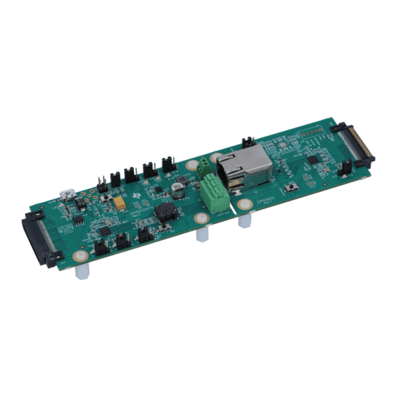
Figure 1-1. DP83TD510E-EVM consists of two PCB's: DP83TD510E Single-Pair-Ethernet board and
SNLU271A – MARCH 2020 – REVISED AUGUST 2020
Submit Document Feedback
ABSTRACT
DP83822I Media-Converter board
Copyright © 2020 Texas Instruments Incorporated
DP83TD510E-EVM User's Guide
1
Advertisement
Table of Contents

Related Manuals for Texas Instruments DP83TD510E-EVM


Summary of Contents for Texas Instruments DP83TD510E-EVM
-
Page 1: Figure 1-1. Dp83Td510E-Evm Consists Of Two Pcb's: Dp83Td510E Single-Pair-Ethernet Board And Dp83822I Media-Converter Board
Nikhil Menon ABSTRACT This User’s Guide discusses how to properly operate and configure the DP83TD510E-EVM. For best layout practices, schematic files, and Bill of Materials, see the associated support documents. Figure 1-1. DP83TD510E-EVM consists of two PCB's: DP83TD510E Single-Pair-Ethernet board and DP83822I Media-Converter board SNLU271A –... -
Page 2: Table Of Contents
6.8 Bottom Layer..................................26 6.9 Bottom Layer Mask................................6.10 Bottom Overlay................................6.11 Board Assembly................................7 Bill of Materials..................................8 Revision History................................... DP83TD510E-EVM User’s Guide SNLU271A – MARCH 2020 – REVISED AUGUST 2020 Submit Document Feedback Copyright © 2020 Texas Instruments Incorporated... - Page 3 Table of Contents List of Figures Figure 1-1. DP83TD510E-EVM consists of two PCB's: DP83TD510E Single-Pair-Ethernet board and DP83822I Media- Converter board..................................Figure 2-1. DP83TD510E-EVM – Top Side..........................Figure 2-2. DP83TD510E-EVM – Bottom Side..........................7 Figure 2-3. DP83TD510E-EVM Block Diagram...........................7 Figure 2-4. Wide-Vin Supply Connection.............................8...
- Page 4 Table 3-2. DP83TD510E Bootstrap Resistor Designation and Suggested Bootstrap Resistor Values........13 Table 7-1. Bill of Materials................................29 Trademarks All other trademarks are the property of their respective owners. DP83TD510E-EVM User’s Guide SNLU271A – MARCH 2020 – REVISED AUGUST 2020 Submit Document Feedback Copyright © 2020 Texas Instruments Incorporated...
-
Page 5: Definitions
Reduced Gigabit Media Independent Interface Start-of-Frame Detection VDDA Analog Core Supply Rail VDDIO Digital Supply Rail Pulldown Pullup Microcontroller Analog Front End SNLU271A – MARCH 2020 – REVISED AUGUST 2020 DP83TD510E-EVM User’s Guide Submit Document Feedback Copyright © 2020 Texas Instruments Incorporated... -
Page 6: Introduction
2 Introduction The DP83TD510E-EVM supports 10-Mbps speed and is IEEE 802.3cg compliant. A DP83822I media converter board is provided for 10BASE-TX Standard Ethernet support and enables bit-error rate testing, interoperability testing, and PMA compliance testing. The EVM also provides on-board tools to configure PHY register using a USB-MDIO graphical user interface tool. -
Page 7: Block Diagram
Introduction Figure 2-2. DP83TD510E-EVM – Bottom Side 2.2 Block Diagram Figure 2-3. DP83TD510E-EVM Block Diagram SNLU271A – MARCH 2020 – REVISED AUGUST 2020 DP83TD510E-EVM User’s Guide Submit Document Feedback Copyright © 2020 Texas Instruments Incorporated... -
Page 8: Operation - Quick Setup
2.3 Operation – Quick Setup The DP83TD510E block of the DP83TD510E-EVM can operate from a single DC supply connected to terminal block J12. The DP83822I media converter board is powered by the VDDIO and VDDA supplies of the DP83TD510E board through the Samtec connector. -
Page 9: Figure 2-5. Dp83Td510E External Supply Connection And Jumpers
Introduction Figure 2-5. DP83TD510E External Supply Connection and Jumpers SNLU271A – MARCH 2020 – REVISED AUGUST 2020 DP83TD510E-EVM User’s Guide Submit Document Feedback Copyright © 2020 Texas Instruments Incorporated... -
Page 10: Board Setup Details
Place shunt at J15 in the "On-Board" position • Place shunt at J16 in the "On-Board" position Note Only populate J9 when powering over USB. DP83TD510E-EVM User’s Guide SNLU271A – MARCH 2020 – REVISED AUGUST 2020 Submit Document Feedback Copyright © 2020 Texas Instruments Incorporated... -
Page 11: Master And Slave Mode Selection - Dp83Td510E
• DP83822I – Write register 0x0017[5]=1 – Write register 0x0017[7]=0 • DP83TD510E – Write register 0x0017[5]=1 – Write register 0x0017[7]=1 SNLU271A – MARCH 2020 – REVISED AUGUST 2020 DP83TD510E-EVM User’s Guide Submit Document Feedback Copyright © 2020 Texas Instruments Incorporated... -
Page 12: Clock Selection - Dp83Td510E
Look for Green LED to illuminate on the RJ45 connector J2 when a link is successfully established (in media convertor mode) • LED_1 will blink for TX/RX activity 3.7 Serial Management Interface The DP83TD510E-EVM supports SMI (MDIO/MDC) through J22, J23 and includes an onboard MSP430F5529 for USB-2-MDIO control. Notes: • DP83TD510E default PHY_ID is 0 •... -
Page 13: Table 3-1. Dp83822 Bootstrap Resistor Designation And Suggested Bootstrap Resistor Values
2.49 RX_DV R103 R108 2.49 OPEN OPEN 2.49 LED_0 R185 R201 2.49 OPEN OPEN 2.49 LED_2 R187 R203 2.49 OPEN SNLU271A – MARCH 2020 – REVISED AUGUST 2020 DP83TD510E-EVM User’s Guide Submit Document Feedback Copyright © 2020 Texas Instruments Incorporated... -
Page 14: Software
MDIO software can be used for accessing the PHY's registers. In the case where an external MSP430 or ezFET is needed, the user may simply connect the TST and RST pins of their device to the DP83TD510E-EVM 4.1 MSP430 Driver Install the latest MSP430 driver from this website: http://software-dl.ti.com/msp430/msp430_public_sw/mcu/... -
Page 15: Schematics
Schematics 5 Schematics SNLU271A – MARCH 2020 – REVISED AUGUST 2020 DP83TD510E-EVM User’s Guide Submit Document Feedback Copyright © 2020 Texas Instruments Incorporated... -
Page 16: Main Power Schematic
Schematics www.ti.com 5.1 Main Power Schematic Figure 5-1. DP83TD510E-EVM Main Power DP83TD510E-EVM User’s Guide SNLU271A – MARCH 2020 – REVISED AUGUST 2020 Submit Document Feedback Copyright © 2020 Texas Instruments Incorporated... -
Page 17: Main Block Schematic
Schematics 5.2 Main Block Schematic Figure 5-2. DP83TD510E-EVM Main Block SNLU271A – MARCH 2020 – REVISED AUGUST 2020 DP83TD510E-EVM User’s Guide Submit Document Feedback Copyright © 2020 Texas Instruments Incorporated... -
Page 18: Interface Schematic
Schematics www.ti.com 5.3 Interface Schematic Figure 5-3. DP83TD510E-EVM Interface DP83TD510E-EVM User’s Guide SNLU271A – MARCH 2020 – REVISED AUGUST 2020 Submit Document Feedback Copyright © 2020 Texas Instruments Incorporated... -
Page 19: Analog Front End Schematic
Schematics 5.4 Analog Front End Schematic Figure 5-4. DP83TD510E-EVM AFE SNLU271A – MARCH 2020 – REVISED AUGUST 2020 DP83TD510E-EVM User’s Guide Submit Document Feedback Copyright © 2020 Texas Instruments Incorporated... -
Page 20: Figure 5-5. Dp83822I Media Converter Afe
Schematics www.ti.com Figure 5-5. DP83822I Media Converter AFE DP83TD510E-EVM User’s Guide SNLU271A – MARCH 2020 – REVISED AUGUST 2020 Submit Document Feedback Copyright © 2020 Texas Instruments Incorporated... -
Page 21: Coms Schematic
Schematics 5.5 COMs Schematic Figure 5-6. DP83TD510E-EVM COMs SNLU271A – MARCH 2020 – REVISED AUGUST 2020 DP83TD510E-EVM User’s Guide Submit Document Feedback Copyright © 2020 Texas Instruments Incorporated... -
Page 22: Header Board
Schematics www.ti.com 5.6 Header Board Figure 5-7. DP83TD510E-EVM break-out connector DP83TD510E-EVM User’s Guide SNLU271A – MARCH 2020 – REVISED AUGUST 2020 Submit Document Feedback Copyright © 2020 Texas Instruments Incorporated... -
Page 23: Hardware Schematic
Schematics 5.7 Hardware Schematic SNLU271A – MARCH 2020 – REVISED AUGUST 2020 DP83TD510E-EVM User’s Guide Submit Document Feedback Figure 5-8. DP83TD510E-EVM Hardware Copyright © 2020 Texas Instruments Incorporated... -
Page 24: Layout
Figure 6-1. Top Overlay 6.2 Top Layer Mask Figure 6-2. Top Layer Mask 6.3 Top Layer Figure 6-3. Top Layer DP83TD510E-EVM User’s Guide SNLU271A – MARCH 2020 – REVISED AUGUST 2020 Submit Document Feedback Copyright © 2020 Texas Instruments Incorporated... -
Page 25: Ground Layer 1
6.4 Ground Layer 1 Figure 6-4. Ground Layer 1 6.5 Signal Layer Figure 6-5. Signal Layer 6.6 Power Layer Figure 6-6. Power Layer SNLU271A – MARCH 2020 – REVISED AUGUST 2020 DP83TD510E-EVM User’s Guide Submit Document Feedback Copyright © 2020 Texas Instruments Incorporated... -
Page 26: Ground Layer 2
Figure 6-7. Ground Layer 2 6.8 Bottom Layer Figure 6-8. Bottom Layer 6.9 Bottom Layer Mask Figure 6-9. Bottom Layer Mask DP83TD510E-EVM User’s Guide SNLU271A – MARCH 2020 – REVISED AUGUST 2020 Submit Document Feedback Copyright © 2020 Texas Instruments Incorporated... -
Page 27: Bottom Overlay
Layout 6.10 Bottom Overlay Figure 6-10. Bottom Overlay 6.11 Board Assembly Figure 6-11. Top Assembly SNLU271A – MARCH 2020 – REVISED AUGUST 2020 DP83TD510E-EVM User’s Guide Submit Document Feedback Copyright © 2020 Texas Instruments Incorporated... -
Page 28: Figure 6-12. Bottom Assembly
Layout www.ti.com Figure 6-12. Bottom Assembly Figure 6-13. Drill Drawing Figure 6-14. Board Dimensions DP83TD510E-EVM User’s Guide SNLU271A – MARCH 2020 – REVISED AUGUST 2020 Submit Document Feedback Copyright © 2020 Texas Instruments Incorporated... -
Page 29: Bill Of Materials
MuRata CAP, CERM, 0.1 uF, 50 V, +/- 20%, X7R, AEC- C59, C67 0.1uF Q200 Grade 1, 0402 0402 CGA2B3X7R1H104M050BB SNLU271A – MARCH 2020 – REVISED AUGUST 2020 DP83TD510E-EVM User’s Guide Submit Document Feedback Copyright © 2020 Texas Instruments Incorporated... - Page 30 CAP, CERM, 4.7 uF, 10 V, +/- 10%, X7S, 0603 0603 C1608X7S1A475K080AC CAP, CERM, 0.22 uF, 10 V, +/- 10%, X5R, C118, C128 0.22uF 0402 0402 GRM155R61A224KE19D MuRata DP83TD510E-EVM User’s Guide SNLU271A – MARCH 2020 – REVISED AUGUST 2020 Submit Document Feedback Copyright © 2020 Texas Instruments Incorporated...
- Page 31 Receptacle, 0.8mm, 30x2, Gold, Edge Mount 30x2, Edge Mount ERF8-030-01-L-D-EM2-TR Samtec Terminal Block, 2x1, Terminal Block, 2x1, 2.54mm, TH 2.54mm, TH 282834-2 TE Connectivity SNLU271A – MARCH 2020 – REVISED AUGUST 2020 DP83TD510E-EVM User’s Guide Submit Document Feedback Copyright © 2020 Texas Instruments Incorporated...
- Page 32 0402 0402 CRCW040227R0JNED Vishay-Dale RES, 2.0 k, 5%, 1 W, AEC-Q200 Grade 0, R19, R124 2.0k 2512 2512 CRCW25122K00JNEG Vishay-Dale DP83TD510E-EVM User’s Guide SNLU271A – MARCH 2020 – REVISED AUGUST 2020 Submit Document Feedback Copyright © 2020 Texas Instruments Incorporated...
- Page 33 RES, 1.00 M, 1%, 0.1 W, 0402 0402 ERJ-2RKF1004X Panasonic RES, 4.87 k, 1%, 0.063 W, AEC-Q200 Grade R121 4.87k 0, 0402 0402 CRCW04024K87FKED Vishay-Dale SNLU271A – MARCH 2020 – REVISED AUGUST 2020 DP83TD510E-EVM User’s Guide Submit Document Feedback Copyright © 2020 Texas Instruments Incorporated...
- Page 34 SH-J6, SH-J7, SH- Single Operation 2.54mm Pitch Open Top 2.54mm Pitch Open J8, SH-J9, SH-J10 Jumper Socket Top Jumper Socket M7582-05 Harwin DP83TD510E-EVM User’s Guide SNLU271A – MARCH 2020 – REVISED AUGUST 2020 Submit Document Feedback Copyright © 2020 Texas Instruments Incorporated...
- Page 35 CAP, CERM, 10 uF, 10 V, +/- 20%, X7T, 0603 0603 GRM188D71A106MA73D MuRata CAP, CERM, 1 uF, 6.3 V, +/- 20%, X7R, 0402 0402 GRM155R70J105MA12D MuRata SNLU271A – MARCH 2020 – REVISED AUGUST 2020 DP83TD510E-EVM User’s Guide Submit Document Feedback Copyright © 2020 Texas Instruments Incorporated...
- Page 36 RES, 5.76 k, 1%, 0.063 W, AEC-Q200 Grade R101, R102 5.76k 0, 0402 0402 CRCW04025K76FKED Vishay-Dale R114 RES, 0, 5%, 0.1 W, 0603 0603 RC0603JR-070RL Yageo DP83TD510E-EVM User’s Guide SNLU271A – MARCH 2020 – REVISED AUGUST 2020 Submit Document Feedback Copyright © 2020 Texas Instruments Incorporated...
- Page 37 RES, 1.50 k, 1%, 0.1 W, 0603 0603 RC0603FR-071K5L Yageo Dual 500mA Low-Noise (3.8μVRMS) LDO Voltage Regulator, RTJ0020D (WQFN-20) RTJ0020D TPS7A8701RTJR Texas Instruments SNLU271A – MARCH 2020 – REVISED AUGUST 2020 DP83TD510E-EVM User’s Guide Submit Document Feedback Copyright © 2020 Texas Instruments Incorporated...
-
Page 38: Revision History
NOTE: Page numbers for previous revisions may differ from page numbers in the current version. Changes from Revision * (March 2020) to Revision A (August 2020) Page • Initial public release............................DP83TD510E-EVM User’s Guide SNLU271A – MARCH 2020 – REVISED AUGUST 2020 Submit Document Feedback Copyright © 2020 Texas Instruments Incorporated... - Page 39 STANDARD TERMS FOR EVALUATION MODULES Delivery: TI delivers TI evaluation boards, kits, or modules, including any accompanying demonstration software, components, and/or documentation which may be provided together or separately (collectively, an “EVM” or “EVMs”) to the User (“User”) in accordance with the terms set forth herein.
- Page 40 www.ti.com Regulatory Notices: 3.1 United States 3.1.1 Notice applicable to EVMs not FCC-Approved: FCC NOTICE: This kit is designed to allow product developers to evaluate electronic components, circuitry, or software associated with the kit to determine whether to incorporate such items in a finished product and software developers to write software applications for use with the end product.
- Page 41 www.ti.com Concernant les EVMs avec antennes détachables Conformément à la réglementation d'Industrie Canada, le présent émetteur radio peut fonctionner avec une antenne d'un type et d'un gain maximal (ou inférieur) approuvé pour l'émetteur par Industrie Canada. Dans le but de réduire les risques de brouillage radioélectrique à...
- Page 42 www.ti.com EVM Use Restrictions and Warnings: 4.1 EVMS ARE NOT FOR USE IN FUNCTIONAL SAFETY AND/OR SAFETY CRITICAL EVALUATIONS, INCLUDING BUT NOT LIMITED TO EVALUATIONS OF LIFE SUPPORT APPLICATIONS. 4.2 User must read and apply the user guide and other available documentation provided by TI regarding the EVM prior to handling or using the EVM, including without limitation any warning or restriction notices.
- Page 43 Notwithstanding the foregoing, any judgment may be enforced in any United States or foreign court, and TI may seek injunctive relief in any United States or foreign court. Mailing Address: Texas Instruments, Post Office Box 655303, Dallas, Texas 75265 Copyright © 2019, Texas Instruments Incorporated...
- Page 44 TI products. TI’s provision of these resources does not expand or otherwise alter TI’s applicable warranties or warranty disclaimers for TI products. Mailing Address: Texas Instruments, Post Office Box 655303, Dallas, Texas 75265 Copyright © 2020, Texas Instruments Incorporated...
Need help?
Do you have a question about the DP83TD510E-EVM and is the answer not in the manual?
Questions and answers