Table of Contents
Advertisement
Quick Links
www.ti.com
User's Guide
DP83869 Evaluation Module
This user's guide details how to properly operate and configure the DP83869EVM. For best layout practices,
schematic files, and Bill of Materials, see the associated support documents.
SNLU237A – SEPTEMBER 2018 – REVISED JANUARY 2024
Submit Document Feedback
ABSTRACT
Copyright © 2024 Texas Instruments Incorporated
DP83869 Evaluation Module
1
Advertisement
Table of Contents

Subscribe to Our Youtube Channel
Related Manuals for Texas Instruments DP83869


Summary of Contents for Texas Instruments DP83869
- Page 1 This user’s guide details how to properly operate and configure the DP83869EVM. For best layout practices, schematic files, and Bill of Materials, see the associated support documents. SNLU237A – SEPTEMBER 2018 – REVISED JANUARY 2024 DP83869 Evaluation Module Submit Document Feedback Copyright © 2024 Texas Instruments Incorporated...
-
Page 2: Table Of Contents
Table 4-10. 1000 M Media Strap Table............................Table 4-11. 4-Pin Dip Switch Modes............................Trademarks All trademarks are the property of their respective owners. DP83869 Evaluation Module SNLU237A – SEPTEMBER 2018 – REVISED JANUARY 2024 Submit Document Feedback Copyright © 2024 Texas Instruments Incorporated... -
Page 3: Definitions
The EVM also supports Fiber protocols 1000BASE-X and 100BASE-FX. The EVM has connections to use the DP83869 MAC Interface in RGMII and SGMII mode. The EVM is also optimized to demonstrate the robust EMI, EMC, and ESD performance of the DP83869 device. -
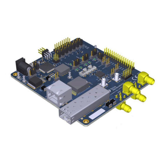
Page 4: Key Features
• Status LEDs – Link – Activity – Power • Bootstraps for Hardware Configuration Figure 2-1. DP83869EVM – Top Side DP83869 Evaluation Module SNLU237A – SEPTEMBER 2018 – REVISED JANUARY 2024 Submit Document Feedback Copyright © 2024 Texas Instruments Incorporated... -
Page 5: Figure 2-2. Dp83869Evm - Bottom Side
Introduction Figure 2-2. DP83869EVM – Bottom Side SNLU237A – SEPTEMBER 2018 – REVISED JANUARY 2024 DP83869 Evaluation Module Submit Document Feedback Copyright © 2024 Texas Instruments Incorporated... -
Page 6: Quick Setup
2.2.3.1 MSP430 Driver Install the latest MSP430 drive from this website: http://software-dl.ti.com/msp430/msp430_public_sw/mcu/ msp430/MSP430_FET_Drivers/latest/index_FDS.html. DP83869 Evaluation Module SNLU237A – SEPTEMBER 2018 – REVISED JANUARY 2024 Submit Document Feedback Copyright © 2024 Texas Instruments Incorporated... - Page 7 J15 connector. Customers can connect a MSP430 launchpad or their own MDIO-MDC utility on J15 to access the PHY registers. SNLU237A – SEPTEMBER 2018 – REVISED JANUARY 2024 DP83869 Evaluation Module Submit Document Feedback Copyright © 2024 Texas Instruments Incorporated...
-
Page 8: Board Setup Details
LED ACT LED SPEED SGMII LED LINK Diodes Strap Resistors Magnetics/ Capacitive JTAG Coupling RJ-45 Figure 3-1. DP83869EVM Block Diagram DP83869 Evaluation Module SNLU237A – SEPTEMBER 2018 – REVISED JANUARY 2024 Submit Document Feedback Copyright © 2024 Texas Instruments Incorporated... -
Page 9: Evm High-Level Summary
Use DP83867 RGMII EVM and SGMII EVM with DP83869EVM. SGMII to RGMII bridge Demonstrate RGMII of DP83869 is able to link-up Connect to DP83867 RGMII EVM over Samtech with RGMII of DP83867 connectors and monitor SGMII SMA on 869 EVM. -
Page 10: Configuration Options
4 Configuration Options 4.1 Bootstrap Options All straps are only two-level straps in DP83869 except PHYADD straps. EVM support one pullup and one pulldown resistor pad on RX_D0 and RX_D2 for PHY address straps. There is only one pullup resistor on all other strap pins with a jumper option to disconnect. -
Page 11: Table 4-3. Phy Strap Table
MODE 2 MODE 3 PHY_ADD3 PHY_ADD2 MODE 0 RX_D1 PHY_ADD[3:2] MODE 1 MODE 2 MODE 3 4.1.2 Strap for DP83869 Functional Mode Selection Table 4-4. Functional Mode Strap Table OPMO OPMO OPMO PIN NAME STRAP NAME PIN NO. DEFAULT FUNCTIONAL MODES... -
Page 12: Table 4-6. 1000Base-X Strap Table
ANEGSEL_1 ANEGSEL_0 Copper : Auto-negotiation ( 1000/100 Advertised), Auto MDIX LED_2 ANEGSEL_1 Copper : Auto Negotiation ( 1000 Advertised), Auto MDIX DP83869 Evaluation Module SNLU237A – SEPTEMBER 2018 – REVISED JANUARY 2024 Submit Document Feedback Copyright © 2024 Texas Instruments Incorporated... -
Page 13: Sgmii/Fiber Interface
SMB connector needs to be used for providing clock input from external sources. Figure 4-2. Onboard Clock Figure 4-3. External Clock Input SNLU237A – SEPTEMBER 2018 – REVISED JANUARY 2024 DP83869 Evaluation Module Submit Document Feedback Copyright © 2024 Texas Instruments Incorporated... -
Page 14: Switch Configuration Options
Green Green 1010 Enable BIST Program failed to program the PHY registers 1011 - 11 - 14 RESERVED RESERVED 1110 DP83869 Evaluation Module SNLU237A – SEPTEMBER 2018 – REVISED JANUARY 2024 Submit Document Feedback Copyright © 2024 Texas Instruments Incorporated... - Page 15 Note When the read loop is stopped, the list of registers to read is cleared. SNLU237A – SEPTEMBER 2018 – REVISED JANUARY 2024 DP83869 Evaluation Module Submit Document Feedback Copyright © 2024 Texas Instruments Incorporated...
-
Page 16: Schematics
Schematics www.ti.com 5 Schematics Figure 5-1. Schematic Page 1 DP83869 Evaluation Module SNLU237A – SEPTEMBER 2018 – REVISED JANUARY 2024 Submit Document Feedback Copyright © 2024 Texas Instruments Incorporated... -
Page 17: Figure 5-2. Schematic
Schematics Figure 5-2. Schematic Page 2 SNLU237A – SEPTEMBER 2018 – REVISED JANUARY 2024 DP83869 Evaluation Module Submit Document Feedback Copyright © 2024 Texas Instruments Incorporated... -
Page 18: Figure 5-3. Schematic
Schematics www.ti.com Figure 5-3. Schematic Page 3 DP83869 Evaluation Module SNLU237A – SEPTEMBER 2018 – REVISED JANUARY 2024 Submit Document Feedback Copyright © 2024 Texas Instruments Incorporated... -
Page 19: Figure 5-4. Schematic
Schematics Figure 5-4. Schematic Page 4 SNLU237A – SEPTEMBER 2018 – REVISED JANUARY 2024 DP83869 Evaluation Module Submit Document Feedback Copyright © 2024 Texas Instruments Incorporated... -
Page 20: Figure 5-5. Schematic
Schematics www.ti.com Figure 5-5. Schematic Page 5 DP83869 Evaluation Module SNLU237A – SEPTEMBER 2018 – REVISED JANUARY 2024 Submit Document Feedback Copyright © 2024 Texas Instruments Incorporated... -
Page 21: Figure 5-6. Schematic
Schematics Figure 5-6. Schematic Page 6 SNLU237A – SEPTEMBER 2018 – REVISED JANUARY 2024 DP83869 Evaluation Module Submit Document Feedback Copyright © 2024 Texas Instruments Incorporated... -
Page 22: Revision History
Changed jumper number from J36 to J35 ......................6 • Updated note in SGMII/Fiber Interface section....................• Changed switch from S3 to S1 ........................14 DP83869 Evaluation Module SNLU237A – SEPTEMBER 2018 – REVISED JANUARY 2024 Submit Document Feedback Copyright © 2024 Texas Instruments Incorporated... - Page 23 STANDARD TERMS FOR EVALUATION MODULES Delivery: TI delivers TI evaluation boards, kits, or modules, including any accompanying demonstration software, components, and/or documentation which may be provided together or separately (collectively, an “EVM” or “EVMs”) to the User (“User”) in accordance with the terms set forth herein.
- Page 24 www.ti.com Regulatory Notices: 3.1 United States 3.1.1 Notice applicable to EVMs not FCC-Approved: FCC NOTICE: This kit is designed to allow product developers to evaluate electronic components, circuitry, or software associated with the kit to determine whether to incorporate such items in a finished product and software developers to write software applications for use with the end product.
- Page 25 www.ti.com Concernant les EVMs avec antennes détachables Conformément à la réglementation d'Industrie Canada, le présent émetteur radio peut fonctionner avec une antenne d'un type et d'un gain maximal (ou inférieur) approuvé pour l'émetteur par Industrie Canada. Dans le but de réduire les risques de brouillage radioélectrique à...
- Page 26 www.ti.com EVM Use Restrictions and Warnings: 4.1 EVMS ARE NOT FOR USE IN FUNCTIONAL SAFETY AND/OR SAFETY CRITICAL EVALUATIONS, INCLUDING BUT NOT LIMITED TO EVALUATIONS OF LIFE SUPPORT APPLICATIONS. 4.2 User must read and apply the user guide and other available documentation provided by TI regarding the EVM prior to handling or using the EVM, including without limitation any warning or restriction notices.
- Page 27 Notwithstanding the foregoing, any judgment may be enforced in any United States or foreign court, and TI may seek injunctive relief in any United States or foreign court. Mailing Address: Texas Instruments, Post Office Box 655303, Dallas, Texas 75265 Copyright © 2023, Texas Instruments Incorporated...
- Page 28 TI products. TI’s provision of these resources does not expand or otherwise alter TI’s applicable warranties or warranty disclaimers for TI products. TI objects to and rejects any additional or different terms you may have proposed. IMPORTANT NOTICE Mailing Address: Texas Instruments, Post Office Box 655303, Dallas, Texas 75265 Copyright © 2024, Texas Instruments Incorporated...
Need help?
Do you have a question about the DP83869 and is the answer not in the manual?
Questions and answers