Table of Contents
Advertisement
Quick Links
Advertisement
Table of Contents

Related Manuals for Texas Instruments DP83826EVM


Summary of Contents for Texas Instruments DP83826EVM
- Page 1 User's Guide SNLU262 – December 2019 DP83826EVM User’s Guide This User’s Guide discusses how to properly operate and configure the DP83826EVM. SNLU262 – December 2019 DP83826EVM User’s Guide Submit Documentation Feedback Copyright © 2019, Texas Instruments Incorporated...
-
Page 2: Table Of Contents
Conducted Emissions 100M MII ................Conducted Emissions 100M RMII Master ..................DP83826EVM Power Schematic ................... DP83826EVM Main Schematic ..............DP83826EVM USB HUB and EZFET Schematic ................DP83826EVM MSP430 and SMI Schematic ................DP83826EVM Breakout Board Schematic List of Tables ........................Terminology .................... -
Page 3: Definitions
Definitions www.ti.com Table 1. Terminology (continued) ACRONYM DEFINITION VDDIO Digital Supply Rail Pulldown Pullup Microcontroller Physical Medium Dependent PRBS Pseudo Random Binary Sequence SNLU262 – December 2019 DP83826EVM User’s Guide Submit Documentation Feedback Copyright © 2019, Texas Instruments Incorporated... - Page 4 50 MHz clock in RMII Master mode is synchronized to the MDI derived clock to improve the system's jitter. The DP83826EVM will demonstrate all features of DP83826. The EVM supports 10BASE-Te and 100BASE-TX Ethernet protocols. The EVM includes connections to use the DP83826 MII and RMII pins through header pins.
-
Page 5: Dp83826Evm - Top Side
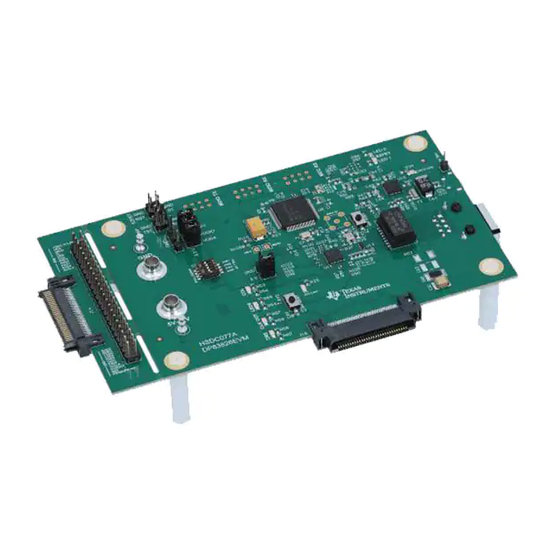
Introduction www.ti.com Figure 1. DP83826EVM – Top Side SNLU262 – December 2019 DP83826EVM User’s Guide Submit Documentation Feedback Copyright © 2019, Texas Instruments Incorporated... -
Page 6: Dp83826Evm - Bottom Side
Introduction www.ti.com Figure 2. DP83826EVM – Bottom Side DP83826EVM User’s Guide SNLU262 – December 2019 Submit Documentation Feedback Copyright © 2019, Texas Instruments Incorporated... -
Page 7: Dp83826Evm Power Headers
Operation – Quick Setup 2.2.1 Power Supply The DP83826EVM power is supplied by the 5-12V input connection in Figure 3. Single supply operation uses on-board LDOs to generate the voltages required for operating various sections of the EVM. Power can also be supplied externally to individual voltage rails. -
Page 8: Dp83826Evm External Msp Connection
The webpage also contains the User’s Guide for installing and using the software. Because the MSP430 is on-board the DP83826EVM, it is not necessary to purchase a separate MSP430 Launchpad kit and connect to the PHY using wires. In the case the on-board MSP430 cannot be used for some reason, MDIO and MDC pins are also broken out on J1 and J2 pins, respectively. -
Page 9: Board Setup Details
Board Setup Details www.ti.com Board Setup Details Block Diagram Figure 6. DP83826EVM Block Diagram SNLU262 – December 2019 DP83826EVM User’s Guide Submit Documentation Feedback Copyright © 2019, Texas Instruments Incorporated... -
Page 10: Configurations Options
Configurations Options MDIO Register Access To update or read the registers of the device, the user can simply connect the DP83826EVM to a computer and use the USB-2-MDIO software. The EVM is designed to easily enable and test strap functionality through software instead without the need to modify the board and hardware. This allows for simple hardware and software support for those that do not have MDIO communication capability. -
Page 11: Block Diagram Setup For Emi Testing
EMI Results www.ti.com Setup Below are a simple diagram and photo outlining the setup of the DP83826EVM in a 10m anechoic chamber. Figure 7. Block Diagram Setup for EMI Testing Figure 8. EMI Testing Setup in Chamber SNLU262 – December 2019 DP83826EVM User’s Guide... - Page 12 EMI Results www.ti.com Results Figure 9. Radiated Emissions 100M MII Figure 10. Radiated Emissions 100M RMII Master DP83826EVM User’s Guide SNLU262 – December 2019 Submit Documentation Feedback Copyright © 2019, Texas Instruments Incorporated...
- Page 13 EMI Results www.ti.com Figure 11. Conducted Emissions 100M MII Figure 12. Conducted Emissions 100M RMII Master SNLU262 – December 2019 DP83826EVM User’s Guide Submit Documentation Feedback Copyright © 2019, Texas Instruments Incorporated...
-
Page 14: Dp83826Evm Power Schematic
2.2uF 10uF 10uF 2.2uF 470pF 165k Green USB_VBUS TL5209DR MCU_VCC ADJ/BYP 100k 10uF 2.2uF 2.2uF 10uF 470pF 165k Green Figure 13. DP83826EVM Power Schematic DP83826EVM User’s Guide SNLU262 – December 2019 Submit Documentation Feedback Copyright © 2019, Texas Instruments Incorporated... -
Page 15: Dp83826Evm Schematics
2.2k 1.00M 1.00M LED_0 4700pF 4700pF 2.49k Green LED_2 2.49k 4700pF Green CLK_OUT Green Green LED_1 LED_3 2.49k 2.49k Figure 14. DP83826EVM Main Schematic SNLU262 – December 2019 DP83826EVM User’s Guide Submit Documentation Feedback Copyright © 2019, Texas Instruments Incorporated... -
Page 16: Dp83826Evm Usb Hub And Ezfet Schematic
RST/SBWTDIO VUSB VSSU 0.22µF AVSS1 MCU_VCC AVCC1 AVSS2 DVCC1 DVSS1 DVCC2 DVSS2 MSP430F5528IRGCR 0.1µF 10uF 0.1µF Figure 15. DP83826EVM USB HUB and EZFET Schematic DP83826EVM User’s Guide SNLU262 – December 2019 Submit Documentation Feedback Copyright © 2019, Texas Instruments Incorporated... -
Page 17: Dp83826Evm Msp430 And Smi Schematic
AVSS2 1.00M AVCC1 DVSS1 DVCC1 DVSS2 DVCC2 MCU_VCC MSP430F5529IPN TEST/SBWTCK RST/SBWTDIO RST/SBWTDIO 10uF 0.1µF 0.1µF 0.1µF 1000pF Figure 16. DP83826EVM MSP430 and SMI Schematic SNLU262 – December 2019 DP83826EVM User’s Guide Submit Documentation Feedback Copyright © 2019, Texas Instruments Incorporated... -
Page 18: Dp83826Evm Breakout Board Schematic
TX_CLK_EXT TX_D0_EXT CLK_OUT_EXT GND_EXT RESET_EXT TX_EN_EXT PWDN_EXT GND_EXT CLK_OUT_EXT RX_ER_EXT PWDN_EXT GND_EXT RESET_EXT GND_EXT GND_EXT ERM8-030-01-L-D-EM2-TR GND_EXT GND_EXT Figure 17. DP83826EVM Breakout Board Schematic DP83826EVM User’s Guide SNLU262 – December 2019 Submit Documentation Feedback Copyright © 2019, Texas Instruments Incorporated... -
Page 19: Dp83826Evm Bom
20%, X7R, AEC- Q200 Grade 1, 1210 10uF CAP, CERM, 10 1210 CGA6P1X7R1E1 uF, 25 V, +/- 06M250AC 20%, X7R, AEC- Q200 Grade 1, 1210 SNLU262 – December 2019 DP83826EVM User’s Guide Submit Documentation Feedback Copyright © 2019, Texas Instruments Incorporated... - Page 20 DP83826EVM BOM www.ti.com Table 4. DP83826EVM BOM (continued) CAP, CERM, 1 0603 CGA3E1X7R1V1 uF, 35 V, +/- 05K080AC 10%, X7R, AEC- Q200 Grade 1, 0603 C27, C28, C29, 22uF CAP, CERM, 22 1210 TMK325B7226K Taiyo Yuden µF, 25 V,+/- 10%, X7R, AEC-...
- Page 21 DP83826EVM BOM www.ti.com Table 4. DP83826EVM BOM (continued) C79, C80 33pF CAP, CERM, 33 0402 GCM1555C1H33 MuRata pF, 50 V,+/- 5%, 0JA16D C0G/NP0, AEC- Q200 Grade 1, 0402 C81, C84 0.22uF CAP, CERM, 0603 CL10A224KB8N Samsung 0.22 µF, 50 V,+/-...
- Page 22 DP83826EVM BOM www.ti.com Table 4. DP83826EVM BOM (continued) 10uH Inductor, Inductor, SRP5030T- Bourns Shielded, Ferrite, 5.7x2.8x5.2mm 100M 10 uH, 2.75 A, 0.128 ohm, SMD R12, R26 24.9k RES, 24.9 k, 1%, 0603 CRCW060324K9 Vishay-Dale 0.1 W, AEC- FKEA Q200 Grade 0,...
- Page 23 DP83826EVM BOM www.ti.com Table 4. DP83826EVM BOM (continued) 2.2k RES, 2.2 k, 5%, 0402 CRCW04022K20 Vishay-Dale 0.063 W, AEC- JNED Q200 Grade 0, 0402 6.49k RES, 6.49 k, 1%, 0402 CRCW04026K49 Vishay-Dale 0.063 W, AEC- FKED Q200 Grade 0, 0402 1.00Meg...
- Page 24 DP83826EVM BOM www.ti.com Table 4. DP83826EVM BOM (continued) SH-J1, SH-J2, Single Operation Single Operation M7582-05 Harwin SH-J3, SH-J4 2.54mm Pitch 2.54mm Pitch Open Top Open Top Jumper Socket Jumper Socket Coupled 9x7mm ACM9070-701- inductor, 5 A, 2PL-TL01 0.01 ohm, SMD...
- Page 25 DP83826EVM BOM www.ti.com Table 4. DP83826EVM BOM (continued) FUSE HLDR 12x5.2mm 0031.7701.11 Schurter CARTRIDGE 125V 5A SMD XTAL1 Crystal, 25 MHz, 2.5x3.2mm ECS-250-12- ECS Inc. 20 ppm, AEC- 33Q-JES-TR Q200 Grade 1, Y1, Y3 Crystal, 24 MHz, 3.2x2.5mm ECS-240-20-33- ECS Inc.
- Page 26 DP83826EVM BOM www.ti.com Table 4. DP83826EVM BOM (continued) R50, R105 2.2k RES, 2.2 k, 5%, 0201 CRCW02012K20 Vishay-Dale 0.05 W, 0201 JNED 1.00Meg RES, 1.00 M, 2010 HVCB2010FKC1 Stackpole 1%, 1 W, 2010 Electronics Inc Automotive DBV0005A SN74LVC1G04Q Texas Catalog Single...
- Page 27 TI products. TI’s provision of these resources does not expand or otherwise alter TI’s applicable warranties or warranty disclaimers for TI products. Mailing Address: Texas Instruments, Post Office Box 655303, Dallas, Texas 75265 Copyright © 2020, Texas Instruments Incorporated...
- Page 28 Mouser Electronics Authorized Distributor Click to View Pricing, Inventory, Delivery & Lifecycle Information: Texas Instruments DP83826EVM...
Need help?
Do you have a question about the DP83826EVM and is the answer not in the manual?
Questions and answers