Advertisement
www.ti.com
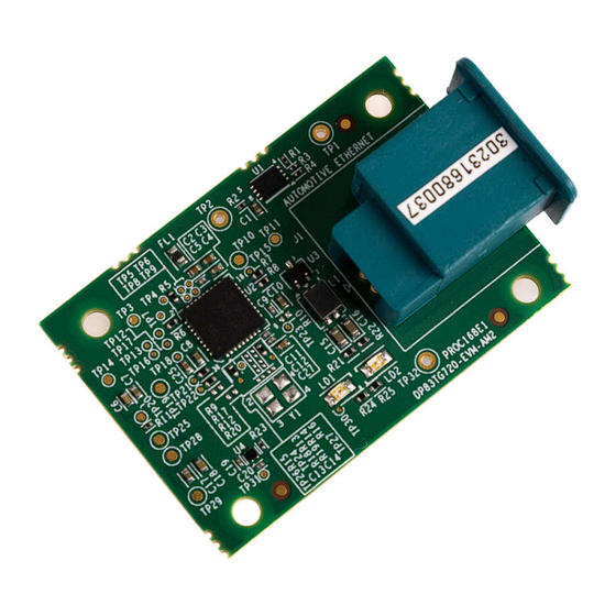
EVM User's Guide: DP83TG720-EVM-AM2
AM2x Evaluation Module for Automotive Ethernet PHY
Add-on Board
Description
The DP83TG720-EVM-AM2 is an Automotive
Ethernet PHY add-on board to be used with AM2x
series Sitara
™
high-performance microcontroller
evaluation modules. This add-on board is an excellent
choice for initial Ethernet evaluation and prototyping
using AM2x EVMs. DP83TG720-EVM-AM2 is
equipped with a TI DP82TG720S-Q1 1000BASE-T1
automotive Ethernet PHY with RGMII & SGMII,
and a MATEnet connector. DP83TG720-EVM-AM2
SPRUJA9 – JANUARY 2024
Submit Document Feedback
is currently supported on
AM263Px MCU PLUS
Features
•
DP83TG720S-Q1
Ethernet PHY with RGMII & SGMII
•
MATEnet Ethernet networking connector
•
Shielded DF40GB 48-pin connector for interfacing
with Sitara
•
Link status and activity LED indicators
•
On-board
AM2x Evaluation Module for Automotive Ethernet PHY Add-on Board
Copyright © 2024 Texas Instruments Incorporated
TMDSCNCD263P
SDK.
1000BASE-T1 automotive
™
AM2x series evaluation modules
TLV755P
LDO
Description
and the
1
Advertisement
Table of Contents

Related Manuals for Texas Instruments DP83TG720-EVM-AM2


Summary of Contents for Texas Instruments DP83TG720-EVM-AM2
- Page 1 AM2x Evaluation Module for Automotive Ethernet PHY Add-on Board Description is currently supported on TMDSCNCD263P and the AM263Px MCU PLUS SDK. The DP83TG720-EVM-AM2 is an Automotive Features Ethernet PHY add-on board to be used with AM2x series Sitara ™ high-performance microcontroller • DP83TG720S-Q1 1000BASE-T1 automotive evaluation modules.
-
Page 2: Kit Contents
• Sitara AM2x EVM Note DP83TG720-EVM-AM2 can be available as a virtual bundle with select Sitara AM2x EVMs. Visit the EVM page on ti.com for more information. 1.3 Device Information The DP83TG720S-Q1 device is an IEEE 802.3bp and Open Alliance compliant automotive Ethernet physical layer transceiver. -
Page 3: Ethernet Connector
EEPROM Automotive Ethernet PHY MATEnet Ethernet Connector TLV755P LDO Status LEDs Figure 2-1. DP83TG720-EVM-AM2 Top Side DF40GB 48-pin shielded connector Figure 2-2. DP83TG720-EVM-AM2 Bottom Side SPRUJA9 – JANUARY 2024 AM2x Evaluation Module for Automotive Ethernet PHY Add-on Board Submit Document Feedback... -
Page 4: Power Requirements
The AM2x EVM Industrial Ethernet PHY Add-on Board is powered from 2.5V and 3.3V inputs from the DF40GB 48-pin connector that interfaces the DP83TG720-EVM-AM2 with the main MCU EVM. There is an on-board that steps the 2.5V input down to 1.0V to supply the DP83TG720S-Q1 VDD inputs. The following sections describe the power distribution network topology that supply the AM2x EVM Industrial Ethernet PHY Add-on Board, supporting components, and reference voltages. - Page 5 Hardware 2.3 Functional Block Diagram Figure 2-4. AM2x Automotive Ethernet PHY Add-on Board Block Diagram SPRUJA9 – JANUARY 2024 AM2x Evaluation Module for Automotive Ethernet PHY Add-on Board Submit Document Feedback Copyright © 2024 Texas Instruments Incorporated...
-
Page 6: Header Information
Hardware www.ti.com 2.4 Header Information The DP83TG720-EVM-AM2 is equipped with a Hirose DF40GB 2x24-pin connector (J2) to connect to Sitara AM2x EVMs. Listed below are the features of this connector relevant to this EVM: • 2x24 pins • Shielded type to support high-speed signals and prevent noise •... -
Page 7: Test Points
Hardware 2.5 Test Points DP83TG720-EVM-AM2 is equipped with multiple test points for hardware debug and bench testing. DP82TG720-EVM-AM2 Test Pointsshows the test points on the board and their associated signal net. Table 2-2. DP83TG720-EVM-AM2 Test Points Test Point Signal... - Page 8 DF40GB connector (J2) and an on-board LDO (U4). Note DP83TG720-EVM-AM2 is configured for VDDIO=3.3V, but can be supplied using VDDIO=2.5V or VDDIO=1.8V On some AM2x EVMs, The RGMII port of the CPSW signals are internally muxed on the same balls of the MCU as the PRU-ICSS Ethernet signals.
- Page 9 2 (3-level) 13kΩ PHY address: 0xC (0b01100) STRP_1 2 (3-level) 13kΩ LED_0 2 (2-level) 2.49kΩ MS=0 LED_1 OPEN Autonomous SPRUJA9 – JANUARY 2024 AM2x Evaluation Module for Automotive Ethernet PHY Add-on Board Submit Document Feedback Copyright © 2024 Texas Instruments Incorporated...
-
Page 10: Integration Guide
Figure 2-8 shows the side profile of the PCB. Figure 2-8. Automotive Ethernet PHY Add-on Board Side Profile AM2x Evaluation Module for Automotive Ethernet PHY Add-on Board SPRUJA9 – JANUARY 2024 Submit Document Feedback Copyright © 2024 Texas Instruments Incorporated... - Page 11 Figure 2-9. DF40GB Connector Mounting Position 2.7.3 Mounting Holes The DP83TG720-EVM-AM2 is designed with mounting holes to securely attach to the main Sitara AM2x MCU EVM. The compatible Sitara AM2x EVMs are designed to have matching mounting holes for an Ethernet Add-on Board to connect to.
- Page 12 2.7.4 MATEnet Ethernet Connector The DP83TG720-EVM-AM2 has a MATEnet Ethernet Connector for sending and receiving signals from the DP83TG720S-Q1 Ethernet PHY. Different Automotive Ethernet PHYs utilize the same connector, and must be used on custom Automotive Ethernet PHY Add-on Boards.
-
Page 13: Additional Information
TPD2E2U06-Q1 Automotive Dual 1.5-pF, 5.5-V, ±25-kV ESD protection diode for USB & High Speed Interfaces • TLV755P 500-mA high-PSRR low-IQ low-dropout voltage regulator with enable SPRUJA9 – JANUARY 2024 AM2x Evaluation Module for Automotive Ethernet PHY Add-on Board Submit Document Feedback Copyright © 2024 Texas Instruments Incorporated... - Page 14 STANDARD TERMS FOR EVALUATION MODULES Delivery: TI delivers TI evaluation boards, kits, or modules, including any accompanying demonstration software, components, and/or documentation which may be provided together or separately (collectively, an “EVM” or “EVMs”) to the User (“User”) in accordance with the terms set forth herein.
- Page 15 www.ti.com Regulatory Notices: 3.1 United States 3.1.1 Notice applicable to EVMs not FCC-Approved: FCC NOTICE: This kit is designed to allow product developers to evaluate electronic components, circuitry, or software associated with the kit to determine whether to incorporate such items in a finished product and software developers to write software applications for use with the end product.
- Page 16 www.ti.com Concernant les EVMs avec antennes détachables Conformément à la réglementation d'Industrie Canada, le présent émetteur radio peut fonctionner avec une antenne d'un type et d'un gain maximal (ou inférieur) approuvé pour l'émetteur par Industrie Canada. Dans le but de réduire les risques de brouillage radioélectrique à...
- Page 17 www.ti.com EVM Use Restrictions and Warnings: 4.1 EVMS ARE NOT FOR USE IN FUNCTIONAL SAFETY AND/OR SAFETY CRITICAL EVALUATIONS, INCLUDING BUT NOT LIMITED TO EVALUATIONS OF LIFE SUPPORT APPLICATIONS. 4.2 User must read and apply the user guide and other available documentation provided by TI regarding the EVM prior to handling or using the EVM, including without limitation any warning or restriction notices.
- Page 18 Notwithstanding the foregoing, any judgment may be enforced in any United States or foreign court, and TI may seek injunctive relief in any United States or foreign court. Mailing Address: Texas Instruments, Post Office Box 655303, Dallas, Texas 75265 Copyright © 2023, Texas Instruments Incorporated...
- Page 19 TI products. TI’s provision of these resources does not expand or otherwise alter TI’s applicable warranties or warranty disclaimers for TI products. TI objects to and rejects any additional or different terms you may have proposed. IMPORTANT NOTICE Mailing Address: Texas Instruments, Post Office Box 655303, Dallas, Texas 75265 Copyright © 2024, Texas Instruments Incorporated...
Need help?
Do you have a question about the DP83TG720-EVM-AM2 and is the answer not in the manual?
Questions and answers