Oasis PGN8EBF Installation Instructions Manual
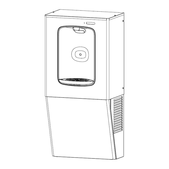
Wall mounted refrigerated bottle filler
Hide thumbs
Also See for PGN8EBF:
- Installation instructions manual (26 pages) ,
- Installation instructions manual (21 pages) ,
- Installation instructions manual (23 pages)

Subscribe to Our Youtube Channel
Related Manuals for Oasis PGN8EBF


Summary of Contents for Oasis PGN8EBF
- Page 1 PGN8EBF PGN8FEBF Wall Mounted Refrigerated Bottle Filler INSTALLATION INSTRUCTIONS...
-
Page 2: Section 1: Getting Started
Section 1: Getting Started What’s Included: Drainpipe Drain Elbow VersaFilter III T15 Torx Screws (Included in Filtered Model Only) Tools & Hardware Required: • Means to cut 1-1/4” drain pipe • Electric drill/driver • • T15 Torx screwdriver and bit Small tubing cutter for plastic line •... -
Page 3: Section 2: Single Level Rough-In Drawing
Section 2: Single Level Rough-In Drawing PGN8EBF: NOTES: 1. TRAP, STOP VALVE AND ELECTRICAL OUTLET NOT FURNISHED. 2. ALLOW 4 INCHES [102MM] MIN. PER SIDE FOR VENTILATION. 3. RECOMMENDED ADULT BARRIER FREE HEIGHT INSTALLATION SHOWN. REDUCE HEIGHT BY 3 INCHES FOR INSTALLATIONS USED PRIMARILY BY CHILDREN AGES 12 AND YOUNGER. -
Page 4: Section 3: Preparation
Section 3: Preparation Read these instructions before installing the unit. 1. Inspect the carton and water cooler for evidence of rough handling and concealed damage. Damage claims should be filed with the carrier. 2. Locate and install plumbing and electrical service, if required, in accordance with Roughing-in Drawing. -
Page 5: Chiller Installation
CHILLER INSTALLATION... - Page 6 Section 4: Chiller Installation 1. Install the wall hanger onto the wall according to the rough-in drawing. See page 3. The Wall hanger is shipped fastened to the back of the chiller unit. Install wall hanger bracket with three chosen anchors (not provided) Refer to rough in drawing for install locations and...
- Page 7 BOTTLE FILLER INSTALLATION...
-
Page 8: Section 4: Installation
Section 4: Installation 1. The PGN8EBF comes partially assembled for shipping. Remove the kit from the packaging and separate it into the assemblies and components shown below. Tool Needed: T15 Torx bit Frame Filter Support Drip Tray Assembly Cabinet Assembly... - Page 9 Section 4: Installation 2. Place the bottle filler frame against the wall and set it onto the top flange of the chiller frame. Align the side edges of the bottle filler and cooler frames to center the frame. 3. Affix the frame to the wall with at least 4 anchors into any appropriate anchor points through the staggered slotted holes.
- Page 10 Section 4: Installation 4. With 4x T15 Torx screws, assemble the drip tray assembly to the center bracket and wall frame. Put IN FRONT OF center bracket 5. Attach the filter support bracket with 2x T15 Torx screws to the frame and drip tray support bracket.
- Page 11 Drainpipes P Trap 7. Assemble PGN8EBF wrapper to the installed frame. Rest the alcove on the drip tray and ensure the wrapper walls rest OUTSIDE of the frame and side brackets. NOTE: The drip tray will hold the weight of the wrapper but it is recommended to keep a hold on the unit during installation for safety.
- Page 12 Section 4: Installation 8. If the outer edge of the drip tray is not properly aligned, loosen the screws mounting the filter support and drip tray bracket to the frame and push forward or back as needed. Then retighten the screws. Slotted Holes...
- Page 13 Section 4: Installation FOR UNFILTERED MODEL ONLY. Route the insulated cold water-out line up into the bottle filler cabinet and connect it to the solenoid valve located in the alcove. Solenoid Valve ¼” Water Line With Insulation Tubing (Provided)
- Page 14 Section 4: Installation FOR FILTERED MODEL ONLY. Connect the preassembled water source line to the shutoff valve. Note that there is an in-line strainer inside the copper tubing of the water source line. IMPORTANT: It is required to keep in-line strainer in system for unit to function properly; removing strainer can cause damage to solenoid valve and/or cartridge system (if applicable).
- Page 15 Section 4: Installation FOR FILTERED MODEL ONLY. After the frame has been installed (not shown), insert the insulated water line from the cold tank into the solenoid located at the top of the alcove assembly. Cooling Tank Water Outlet Solenoid Valve Inlet Cooling Tank Water Outlet Line From...
- Page 16 Section 4: Installation 10. Connect the IEC connector to the power brick located behind the alcove of the bottle filler. It is recommended to route the power cord from side opposite of the condenser fan to ensure it does not become an obstruction. Power Brick IEC Connector FOR UNFILTERED MODEL ONLY.
- Page 17 Section 4: Installation FOR FILTERED MODEL ONLY. 10. Install the provided filter cartridge by inserting the cartridge into the filter head and then rotating 90 degrees until secured. 11. To flush the filter, ensure that the condenser fan is free from obstructions and plug in the unit, then turn on the water source.
- Page 18 Section 4: Installation 12. Once the unit has been verified to be functioning properly, install the front cover panel by inserting the top flanch up between the wrapper and center bracket, then tipping the panel back to the fountain. Secure it with the 2x #8 hex or 2x T15 screws at the base of the unit.
-
Page 19: Section 5: Set-Up Guide For Oasis Electronics
® Section 5: Set-Up Guide For OASIS Hands-Free Bottle Filler Electronics •Factory default program settings are: • Bottle Count = 0.5L (1 Bottle) • Units - Gallons • Flow Rate = 1.2 GPM • Unfiltered unit • 20 second maximum dispense time •... -
Page 20: Section 6: Bottle Filler Parts Breakdown
Section 6: Bottle Filler Parts Breakdown Item QTY P/N Description Item QTY P/N Description 041245-004 Frame 042374-001 Grille, Drip Tray 041250-001 Panel, Front 026675-003 Screw, Flat HD Tapping 041241-001 Panel, Filter 041207-001-SP Power Cord Assembly 041238-006 Wrapper 038036-003 Power Supply, 100-240VAC/12VDC A020967 1-1/2"... -
Page 21: Section 7: Chiller Parts Breakdown
Insulation, Sponge Tube 26" 034343-003 Drier W/O Process Port Tube, PE Cut Length WHI 27" 030152-097-SP 041243-002 Bracket, ONN Center For PGN8EBF Only ITEM Description 035504-010-SP WATER LINE SA INLET For PGN8FEBF Only ITEM Description 030152-021-SP TUBE, PE CUT LENGTH WHI 24.0"... -
Page 22: Section 8: Maintenance And Decommissioning
Section 8: Maintenance and Decommissioning Maintenance 1. Inspection of condenser should be made at 3-month intervals. To remove dirt and lint from condenser, disconnect power supply cord, then use small stiff non-wire or vacuum cleaner attachment brush. Observance of this procedure will ensure adequate air circulation through condenser so operation is efficient and economical. - Page 23 WARNING The warranty and the Underwriters' Laboratory Listing for this machine are automatically voided if this machine is altered, modified, or combined with any other machine or device. Alteration or modification of this machine may cause serious flooding and/or hazardous electrical shock or fire. EXCEPT AS SET FORTH HEREIN, THE MANUFACTURER MAKES NO OTHER WARRANTY, GUARANTEE OR AGREEMENT EXPRESSED, IMPLIED OR STATUTORY, INCLUDING ANY IMPLIED WARRANTY OR MERCHANTABILITY OR...
- Page 24 Wall Mounted Refrigerated Bottle Filler Installation Instructions P/N 030099-704 Date: 02/2023 OASIS INTERNATIONAL 222 East Campus View Blvd. © 2023 LVD Acquisition, LLC Columbus, OH 43235 Oasis is a registered trademark of LVD Acquisition, LLC dba 614-861-1350 Oasis International www.oasiscoolers.com...
Need help?
Do you have a question about the PGN8EBF and is the answer not in the manual?
Questions and answers