Advertisement
Quick Links
Advertisement

Related Manuals for WATSON Mastermind Flow


Summary of Contents for WATSON Mastermind Flow
- Page 1 ASSEMBLY Mastermind Flow V.21.0 2/2024 360.394.1300 watsonfurniture.com...
-
Page 2: Important Safety Instructions
Important Safety Instructions This product is for commercial use only. Maximum intended load for each worksurface is 200 lbs (91 kg) When using an electrical furnishing, basic precautions should always be followed, including the following: Read all instructions before using (this furnishing). DANGER To reduce the risk of electric shock: 1. - Page 3 12. Electrical connection between rail segments shall be disconnected prior to removal of a mechanical connection. 13. The system may be supplied by a three phase power system with four individual circuits rated at 20 amps/120 volts max-imum, or as permitted by local code. 14.
- Page 4 Tools Additional tools such as a 90 Degree Bit and an 18” Extension are helpful for some steps. *No torque or ball bits should be used Phillips Drill/ 5mm Hex Drill/ 90 DGREE BIT Electric Drill Driver Bit Driver Bit 18”...
-
Page 5: Essential Components
Essential Components Optional Cable Tray Leg Mount Traverse Plastic Nut End Cover Short Long Longest Traverse Traverse Traverse Traverse Adder Ender Corner Surface Surface Surface... - Page 6 Section 1 Install Plastic Nut Assembly. Align and insert Plastic Nut Assembly into holes on Leg Mount Casting (1a thru 1e). Align Plastic Nut Assembly with notches in the Leg Mount Casting (See Figure 1). Fig. 1 CHANNEL IN PLASTIC NUT ASSEMBLY ALIGNED IN SAME DIRECTION AS TRAVERSE END COVERS...
- Page 7 Install Traverse End Covers. Align and attach Traverse End Covers to Leg Mount Castings wherever there is a Plastic Nut Assembly installed (2a thru 2e). Refer to Fig. 2 for locations for the rest of the Traverse End Covers. Fig. 2...
- Page 8 Attach Traverses. Slide Traverses over each Traverse End Cover (3a and 3b) to attach the Legs and build the Base. Assemble as shown. SHORT TRAVERSE TRAVERSE LONG TRAVERSE LONGEST TRAVERSE...
- Page 9 Attach Traverses (continued). Slide Traverses over each Traverse End Cover (3c thru 3e) to attach the Legs and build the Base. Assemble as shown. SHORT TRAVERSE TRAVERSE LONG TRAVERSE LONGEST TRAVERSE...
- Page 10 Secure Base. T h i s s i d e c o n n e c t s t o S e c t i o n Screw, M8 X 25MM, Flat Head (0002678)
- Page 12 Section 2 Install Plastic Nut Assembly. Align and insert Plastic Nut Assembly into holes on Leg Mount Casting. Align Plastic Nut Assembly with notches in the Leg Mount Casting (See Figure 1). PLASTIC NUT ASSEMBLY LEG MOUNT CASTING PLASTIC NUT ASSEMBLY Fig.
- Page 13 Install Traverse End Covers. Align and attach Traverse End Covers to Leg Mount Castings wherever there is a Plastic Nut Assembly installed. Refer to Fig. 2 for locations for the rest of the Traverse End Covers. TRAVERSE END COVER Fig.2...
- Page 14 Section 3 Install Plastic Nut Assembly. Align and insert Plastic Nut Assembly into holes on Leg Mount Casting (1a thru 1e). Align Plastic Nut Assembly with notches in the Leg Mount Casting (See Figure 1). Fig. 1 CHANNEL IN PLASTIC NUT ASSEMBLY ALIGNED IN SAME DIRECTION AS TRAVERSE END COVERS...
- Page 15 Install Traverse End Covers. Align and attach Traverse End Covers to Leg Mount Castings wherever there is a Plastic Nut Assembly installed (2a thru 2e). Refer to Fig. 2 for locations for the rest of the Traverse End Covers. Fig. 2...
- Page 16 Section 3: Attach Traverses. Slide Traverses over each Traverse End Cover (3a and 3b) to attach the Legs and build the Base. Assemble as shown. SHORT TRAVERSE TRAVERSE LONG TRAVERSE LONGEST TRAVERSE...
- Page 17 Section 3: Attach Traverses (continued). Slide Traverses over each Traverse End Cover (3c thru 3e) to attach the Legs and build the Base. Assemble as shown. SHORT TRAVERSE TRAVERSE LONG TRAVERSE LONGEST TRAVERSE...
- Page 18 Secure Base. c t i o n t o S e e c t s c o n n s i d e T h i s...
- Page 20 Attaching Sections Together Attaching Section 1 to Section 2 Slide Traverses over each Traverse End Cover (1a thru 1c) to attach the Legs and build the Base. Assemble as shown. SHORT TRAVERSE TRAVERSE LONG TRAVERSE LONGEST TRAVERSE...
- Page 21 Attaching Section 3 to Section 2 (continued) Slide Traverses over each Traverse End Cover (1d thru 1f) to attach the Legs and build the Base. Assemble as shown. SHORT TRAVERSE TRAVERSE LONG TRAVERSE LONGEST TRAVERSE...
- Page 22 Secure Base. Screw, M8 X 25MM, Flat Head (0002678)
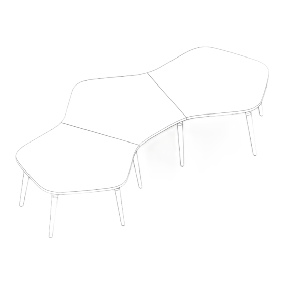
- Page 24 Attaching the Worksurfaces Place Top Surfaces onto Base (1a) making sure the Table Mount Castings (pre-installed) (1b) are placed into the receiving ends of each Leg Mount Casting (1c). Ender Surface Adder Surface TABLE MOUNT CASTING Starter Surface LEG MOUNT CASTING...
- Page 25 Turn all fourteen (14) locking components in leg 90° to secure top. LOCKING COMPONENT...
- Page 26 Attach Optional Cable Tray. Align each Cable Tray with five (5) pilot holes in the surface (3a). Attach the each Cable Tray using five (5) #10 x 5/8” Phillips Head Screws (3b). CABLE TRAY Screw, #10 x 5/8, BK, Phillips (0002148)
Need help?
Do you have a question about the Mastermind Flow and is the answer not in the manual?
Questions and answers