Table of Contents
Advertisement
Quick Links
LR8101
LR8102
DATA LOGGER
Read carefully before use.
Keep for future reference.
When using the instrument for the
first time
Safety Information
Part Names and Functions
Settings and Operations
Dec. 2023 Edition 1
LR8102A961-00
p.11
p.30
p.77
HIOKI LR8102A961-00
Instruction Manual
Troubleshooting
Maintenance and Service
Error Messages
p.347
p.350
EN
[600659720]
Advertisement
Table of Contents

Subscribe to Our Youtube Channel
Related Manuals for Hioki LR8101


Summary of Contents for Hioki LR8101
- Page 1 LR8101 LR8102 Instruction Manual DATA LOGGER Read carefully before use. Keep for future reference. When using the instrument for the Troubleshooting first time Safety Information p.11 Maintenance and Service p.347 Part Names and Functions p.30 Error Messages p.350 ...
- Page 2 HIOKI LR8102A961-00...
-
Page 3: Table Of Contents
Set the synchronized terminal ..........29 LR8102 only Data refresh interval of the Part Names and Functions ....30 measurement modules ......90 ...30 LR8101 and LR8102 Data Loggers Setting the Voltage/Temp Module ..94 Options ...........33 Voltage measurement .......94 ......33 Measurement modules Temperature (thermocouple) ..........34... - Page 4 Output (I/O) Terminals .......243 Starting multiple measurements Setting Alarms ........185 .247 simultaneously using the external trigger Alarm condition settings that apply to all 11.3 Setting the External Sampling channels ..........185 (SMPL) ..........248 ....189 Settings for each alarm channel HIOKI LR8102A961-00...
- Page 5 Output ..........340 14.15 Command Samples ......341 Specifications 14.16 File Name and Directory Name ..343 14.17 External View ........344 13.1 Specifications of Data Logger ...293 LR8101 ..........344 ......293 General Specifications LR8102 ..........344 Recording ..........298 ............345 M7100 File ............299 ............345...
- Page 6 Contents Maintenance and Service 15.1 Repair, Correction, and Cleaning ..347 15.2 Troubleshooting ........349 Before returning for repair .......349 ........350 Error messages Normalization process ......356 15.3 Disposal ..........357 15.4 FAQ (Frequently Asked Questions) .359 15.5 Open-source Software .......361 HIOKI LR8102A961-00...
-
Page 7: Introduction
The LR8102 Data Logger is a model based on the LR8101 with additional functions as follows. • Function to synchronize sampling between instruments •... -
Page 8: Symbols And Abbreviations
“Operating Precautions”. Indicates that the entire device is protected with double or reinforced insulation. Indicates the power push-button switch that toggles the instrument between on and off. Indicates a grounding terminal. Indicates DC (Direct Current). Indicates alternating current (AC). HIOKI LR8102A961-00... - Page 9 (S/s). × Example: 20 MS/s (20 megasamples per second) signifies 20 samples per second. Accuracy labeling The instrument accuracy is expressed by defining a limit value for errors in terms of the same unit as the measured value. HIOKI LR8102A961-00...
-
Page 10: Checking Package Contents
• Instruction Manual • Logger Utility • Logger Utility Instruction Manual • CAN Editor • CAN Editor Instruction Manual • Communication Command Instruction Manual • GENNECT One *1. The latest edition can be downloaded from the Hioki website. HIOKI LR8102A961-00... -
Page 11: Options (Sold Separately)
The options listed below are available for the instrument. See “1.3 Options” (p. 33). To place orders, contact your authorized Hioki distributor or reseller. Options are subject to change. Check Hioki’s website for the latest information. M7100 Voltage/Temp Module (15 channels) - Page 12 MAINS installation. (CAT IV) Example: Measurements on devices installed before the main fuse or circuit breaker in the building installation. Distribution panel Service entrance Interior wiring Service drop CAT II CAT III CAT IV Outlet Power meter Fixed equipment HIOKI LR8102A961-00...
-
Page 13: Usage Notes
„ Use of the instrument while it is malfunctioning could result in serious bodily injury. If you find any malfunction or damage, contact your authorized Hioki distributor or reseller. See “2.1 Inspection Before Use” (p. 37) for information about inspections. - Page 14 The instrument is classified as a Class A device under the EN 61326 standard. Use of the instrument in a residential setting such as a neighborhood could interfere with reception of radio and television broadcasts. In such cases, the operator should take appropriate measures to address the issue. HIOKI LR8102A961-00...
- Page 15 Doing so could result in serious bodily injury or damage to the instrument. These rated voltages vary depending on the measurement modules. See “13 Specifications” (p. 2 93) for these values. Module 10 LR 8101 M 7100 LR81 02 Module 10 LR8101 M 7100 LR8102 − − − − Maximum voltage Maximum voltage −...
- Page 16 A physical phenomenon called short range ordering occurs in K and T thermocouples. This ° ° phenomenon may prevent accurate measurement between 250 C and 600 Select the sensor while referring to the manufacturer of the thermocouples to be used. HIOKI LR8102A961-00...
- Page 17 However, do not use the original box or cushioning material if the box is torn or deformed or the material is crushed. If you are unable to use the original box and cushioning material, contact your authorized Hioki distributor or reseller. • Before packing the instrument, be sure to disconnect the power cords.
-
Page 18: About This Manual
The measurement is completed with one recording. and measured value in the REPEat Repetitive recording ON (Response) format. The recording is repeated. STOP Executing the command ends the measurement. Setting item and description The configurable item and its description. HIOKI LR8102A961-00... -
Page 19: Communication Method
These messages are the commands to query the results of Query program messages operations, measurements, and the setting status of the instrument. The command program messages and the query program messages are collectively referred to as the commands. (The commands are written in Hioki's proprietary SCPI language.) HIOKI LR8102A961-00... -
Page 20: Message Format
See “Header” (p. 2 1), “Separator” (p. 2 2), and “Data part” (p. 2 3). Response messages The response message is created after a query message is received and its syntax is checked. If any error occurs when a query message is received, no response message is created for the query message. HIOKI LR8102A961-00... -
Page 21: Command Syntax
:SYSTem:DATE? Combined command Header that consists of multiple single command header headers separated with colons ( *IDN? Standard command Header that starts with an asterisk ( ) indicating the header standard command header (as specified in IEEE 488.2) HIOKI LR8102A961-00... -
Page 22: Message Terminator
A message with a header and data can be separated into the header and data parts by using a space (blank). :HEADer ON Example: Space (3) Data separator A message with multiple data sets requires commas ( ) between the data sets. :SYSTem:COMMunicate:LAN:IPADdress 192,168,1,1 Example: Comma HIOKI LR8102A961-00... -
Page 23: Data Part
• NR1 integral number data (example: +12, −23, 34) • NR2 decimal fraction data (example: +1.23, −23.45, 3.456) • NR3 floating-point exponential notation data (example: +1.0E-2, −2.3E+4) The format including all of the three formats above is referred to as the “NRf” format. HIOKI LR8102A961-00... - Page 24 • In the commands, a single quotation ( ) can be used instead of a double quotation ( The special characters can be entered as follows. Ω ° ± " µ ε LR8101, LR8102 :COMMent:TITLe 'HIOKI' Example: :COMMent:TITLe "HIOKI" :COMMent:TITLe "~o" HIOKI LR8102A961-00...
-
Page 25: Abbreviation Of Combined Command Header
The single and combined command headers require no colon ( ) at the beginning. However, it is recommended to place a colon ( ) at the beginning of a command in order to prevent confusion with abbreviated forms and avoid malfunction. HIOKI LR8102A961-00... -
Page 26: Output Queue And Input Buffer
Event Status Register 0 (read out with Logical sum NF (LF) Data are stored in Data the output queue Data Data *ESR? Standard Event Status Register (read out with Data Output queue Logical sum Status Byte Register Read out ESB MAV ESBO *STB? with HIOKI LR8102A961-00... - Page 27 Bit 1 Request of controller privilege (unused) (RQC) Unused (0) Bit 0 Operation completed *OPC (OPC) Set only for the command. To read out the Standard Event Status Register, use the following command. *ESR? Standard Event Status Register HIOKI LR8102A961-00...
-
Page 28: Items To Be Initialized To The Default Status
Status byte register – * Event register * – Enable register – – Current path – – *1. Other than the MAV bit are cleared. *2. The PON bit (bit 7) is excluded. HIOKI LR8102A961-00... -
Page 29: Overview
1.1 Product Overview and Features The instrument is a multichannel data logger that combines individual measuring modules. It is used for recording physical readings, including temperatures and voltages. Both LR8101 and LR8102 Choice of modules according to applications Features Modules Maximum rated line-to-ground voltage is 1500 V. -
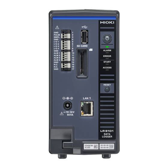
Page 30: Part Names And Functions
Part Names and Functions 1.2 Part Names and Functions LR8101 and LR8102 Data Loggers Front Rear LR8101 LR8102 Name Function Reference USB connector Optional USB drive can be connected. p. 5 9 External control Allows you to control the instrument with external signals. - Page 31 • When the instrument is updated, the LEDs blink in sequence according to the progress. ALARM → ERROR → START → ACCESS • When the ROM and RAM of the instrument are checked, the LEDs blink in sequence according to the progress. ALARM → ERROR → START → ACCESS HIOKI LR8102A961-00...
- Page 32 Alarm hold clear Pressing the key once during alarm hold cancels the hold p. 1 85 status. Side LR8101, LR8102 Right side Left side Name Function Reference Indicates the operation of the LED located at the front of the Description of the LED p. ...
-
Page 33: Options
Do not remove it as the number is required for management. Share this number when contacting your reseller. Connecting plate The plate for connecting the measurement modules. After connecting the modules, fix the plate using screws. HIOKI LR8102A961-00... -
Page 34: Other Options
L6101 Optical Connection Cable (1 m) L6102 Optical Connection Cable (10 m) The optical connection cable is required for synchronizing multiple units of LR8102. 9713-01 CAN Cable Option for LR8102. The CAN Cable is used for CAN output. Length: 2.0 m HIOKI LR8102A961-00... -
Page 35: Measurement Workflow
• Set the input types and ranges for the voltage, thermocouple, etc. 6. Start and stop the measurement See “3.9 Starting and Stopping Measurement” (p. 118). STARt • Send the command to start the measurement. STOP • Send the command to stop the measurement. HIOKI LR8102A961-00... - Page 36 7. Acquire the waveform data See “4 Acquiring Measurement Data” (p. 1 23). See “4.2 Acquiring Realtime Data” (p. 127). Select an appropriate data acquisition method according to the application. See “4.7 Comparison of Realtime Data Acquisition” (p. 136). HIOKI LR8102A961-00...
-
Page 37: Connection (Preparation For Measurements)
Inspect the instrument before turning ON the power, and ensure that no damage occurred during storage or shipping. If you find any damage, contact your authorized Hioki distributor or reseller. Inspecting the peripheral devices Inspect the measurement cables to confirm that the insulation is not worn and no metal parts are exposed. -
Page 38: Connecting The Measurement Modules
Failure to do so could cause the operator to experience an electric shock or damage the instrument and measurement modules. Connecting the Measurement Modules to the Instrument Applicable modules: M7100, M7102 Required items: Phillips screwdriver (No. 2) Turn OFF the instrument and remove the AC adapter. Remove the connector covers. HIOKI LR8102A961-00... - Page 39 Connecting an additional measurement module An additional measurement module can be installed on the left side of the first measurement module. Connect the additional measurement module in the same way as you connected the first measurement module to the instrument. HIOKI LR8102A961-00...
-
Page 40: Connecting The Ac Adapter
To prevent the plug from coming off, press the output cord of the AC adapter cable into the cable hook of the instrument. Connect the plug of the power cord to the outlet. HIOKI LR8102A961-00... -
Page 41: Connecting An External Power Supply
DC power supply. IMPORTANT When a power cord that is 3 m or longer is connected, the instrument may be affected by factors in the EMC environment, such as exogenous noise. HIOKI LR8102A961-00... -
Page 42: Connecting Cables
EMC environment, such as exogenous noise. Position the cable away from the power line or ground cable. • When the cable is connected in parallel to other equipment, measurement values may vary. If the measurement cable is to be connected in parallel, make sure to check the operation before use. HIOKI LR8102A961-00... - Page 43 The ground of the external control terminal and the ground of the instrument are common and they are not isolated from each other. When using a twisted pair wire for the measurement cable, take care not to allow the measurement cable to contact adjacent measurement cables or terminals. HIOKI LR8102A961-00...
-
Page 44: Wiring The Voltage Cable And Thermocouple
The color scheme for the cable sheath varies with different countries and manufacturers. Confirm the colors before connecting the cable. Connect the cable to the measurement target. Close the terminal block cover. Tighten the screw for the terminal block cover. HIOKI LR8102A961-00... - Page 45 (p. 95). Shunt resistor Ω IMPORTANT Be sure to fix the terminal block cover using the screw. If the terminal block cover is not closed, the measured values may be affected. HIOKI LR8102A961-00...
- Page 46 Close the terminal block cover. Tighten the screw for the terminal block cover. IMPORTANT Be sure to fix the terminal block cover using the screw. If the terminal block cover is not closed, the measured values may be affected. HIOKI LR8102A961-00...
-
Page 47: Wiring For The Pulse Input
While holding down the button, insert the minus (-) cable into the terminal hole. Remove the flat-head screwdriver from the button. The cable is locked. Pull the cable gently and confirm that the cable will not come out. HIOKI LR8102A961-00... -
Page 48: Wiring For The Alarm Output
Five ground terminals are available. The cable can be connected to any of the ground terminals. While holding down the button, insert the cable into the terminal hole. Remove the flat-head screwdriver from the button. The cable is locked. Pull the cable gently and confirm that the cable will not come out. HIOKI LR8102A961-00... -
Page 49: Wiring For External Control
Five ground terminals are available. The cable can be connected to any of the ground terminals. While holding down the button, insert the cable into the terminal hole. Remove the flat-head screwdriver from the button. The cable is locked. Pull the cable gently and confirm that the cable will not come out. HIOKI LR8102A961-00... -
Page 50: Wiring For The External Sampling
While holding down the button, insert the minus (-) cable into the terminal hole. Remove the flat-head screwdriver from the button. The cable is locked. Pull the cable gently and confirm that the cable will not come out. HIOKI LR8102A961-00... -
Page 51: Wiring The Can Cable (Lr8102 Only)
Five ground terminals are available. The cable can be connected to any of the ground terminals. Remove the flat-head screwdriver from the button. The cable is locked. Pull the cable gently and confirm that the cable will not come out. HIOKI LR8102A961-00... - Page 52 See CAN Editor Instruction Manual “5.4 Setting the Communication Method of the CAN Unit”. Check that there is a channel for which the output is ON. See CAN Editor Instruction Manual “7.5 Selecting the Channel to be Output”. HIOKI LR8102A961-00...
-
Page 53: Wiring The Optical Connection Cable (Lr8102 Only)
Connect the OUT terminal of the optical synchronization connector of the secondary unit and the IN terminal of the optical synchronization connector of another secondary unit using an optical connection cable. Repeat this step until all the IN terminals of the optical synchronization connectors of the secondary units are connected. HIOKI LR8102A961-00... - Page 54 • A synchronization error occurs if either of the power supplies for the primary and secondary units is turned OFF. • Use primary and secondary units with the same version. Using different versions results in a synchronization error. HIOKI LR8102A961-00...
-
Page 55: Turning On And Off The Power
Procedure to turn off the instrument When the POWER key is pressed, the LEDs blink for 5 seconds. Pressing the POWER key again while the LEDs are blinking turns OFF the power. The POWER LED is turned OFF. POWER LED HIOKI LR8102A961-00... -
Page 56: Sd Memory Card And Usb Drive
The SD memory card, the USB drive, or the instrument can be damaged. Do not transport the instrument while it is connected to a USB drive. „ The USB drive or the instrument can be damaged. HIOKI LR8102A961-00... - Page 57 They lose the ability to store and load data after extended or frequent use. If you encounter this issue, purchase a new drive. Hioki is not liable for data stored on SD memory cards or USB drives, regardless of the nature or cause of the accident or damage involved.
-
Page 58: Installing And Removing An Sd Memory Card
Make sure that the instrument is not accessing (saving, loading, etc.) the SD memory card. Confirm that the ACCESS LED is turned OFF. Press and release the SD memory card. When the card is partially pushed out, pinch the card and pull it out. HIOKI LR8102A961-00... -
Page 59: Installing And Removing A Usb Drive
Check the connection between the USB drive and the USB connector. Insert the USB drive completely. Removing the USB drive Make sure that the instrument is not accessing (saving, loading, etc.) the USB drive. Confirm that the ACCESS LED is turned OFF. Pull out the USB drive. HIOKI LR8102A961-00... -
Page 60: Setting And Connecting The Lan
Be sure to configure the LAN settings before connecting the instrument to the network. If you change the settings while the instrument is connected to a network, the instrument may have the same IP address as another device on the LAN, causing incorrect address information to be sent to the LAN. HIOKI LR8102A961-00... - Page 61 (Setting is not required when using DHCP server, because the address is obtained from the server.) DNS: used/not used IP address (when used): ___.___.___.___ (Setting is not required when using DHCP server, because the address is obtained from the server.) HIOKI LR8102A961-00...
- Page 62 If a server that allows you to obtain the IP addresses using the names is operating on the network, the IP address of the communication partner can be looked up from the name by querying the server. If the DHCP server is enabled, the setting will be obtained from the server. HIOKI LR8102A961-00...
-
Page 63: Network Settings On Pc
Right-click the icon of the adapter to be used for communications (named [Local Area Connection], [Ethernet], etc.), and then select [Properties]. Select [Internet Protocol Version 4 (TCP/ IPv4)], and then click [Properties]. Enter [IP address] [Subnet mask], then click [OK]. HIOKI LR8102A961-00... - Page 64 [Subnet mask] (Automatically set) [Gateway]: [ON] [Gateway]: [OFF] Settings for connecting [Gateway IP] to another network as well (using a [DNS]: [ON] gateway) [DNS]: [OFF]* [DNS IP]* Update the settings Connection Connect a LAN cable *1. LAN1 only HIOKI LR8102A961-00...
- Page 65 Settings :SYSTem:COMMunicate:LAN:HOSTname "A$" Syntax Command :SYSTem:COMMunicate:LAN:HOSTname "LOGGER" Example :SYSTem:COMMunicate:LAN:UPDate Query :SYSTem:COMMunicate:LAN:HOSTname? Syntax Query :SYSTem:COMMunicate:LAN:HOSTname:PREParation? "A$" Response :SYSTem:COMMunicate:LAN:HOSTname? Example :SYSTEM:COMMUNICATE:LAN:HOSTNAME "LOGGER" (Response) (When the header is ON) Parameter = Character string of host name (up to 12 single-byte characters) HIOKI LR8102A961-00...
- Page 66 :SYSTem:COMMunicate:LAN:SMASk 255,255,255,0 Example :SYSTem:COMMunicate:LAN:UPDate Query :SYSTem:COMMunicate:LAN:SMASk? Syntax Query :SYSTem:COMMunicate:LAN:SMASk:PREParation? mask1<NR1>mask2<NR1>,mask3<NR1>,mask4<NR1> Response :SYSTem:COMMunicate:LAN:SMASk? Example :SYSTEM:COMMUNICATE:LAN:SMASK 255,255,255,0 (Response) (When the header is ON) Parameter mask1 0 to 255 mask2 0 to 255 mask3 0 to 255 mask4 0 to 255 HIOKI LR8102A961-00...
- Page 67 :SYSTem:COMMunicate:LAN:GATeway ip1,ip2,ip3,ip4 Syntax Command :SYSTem:COMMunicate:LAN:GATeway 192,168,1,100 Example :SYSTem:COMMunicate:LAN:UPDate Query :SYSTem:COMMunicate:LAN:GATeway? Syntax Query :SYSTem:COMMunicate:LAN:GATeway:PREParation? ip1<NR1>,ip2<NR1>,ip3<NR1>,ip4<NR1> Response :SYSTem:COMMunicate:LAN:GATeway? Example :SYSTEM:COMMUNICATE:LAN:GATEWAY 192,168,1,100 (Response) (When the header is ON) Parameter 0 to 255 0 to 255 0 to 255 0 to 255 HIOKI LR8102A961-00...
- Page 68 :SYSTem:COMMunicate:LAN:DNS ip1,ip2,ip3,ip4 Syntax Command :SYSTem:COMMunicate:LAN:DNS 192,168,1,100 Example :SYSTem:COMMunicate:LAN:UPDate Query :SYSTem:COMMunicate:LAN:DNS? Syntax Query :SYSTem:COMMunicate:LAN:DNS:PREParation? ip1<NR1>,ip2<NR1>,ip3<NR1>,ip4<NR1> Response :SYSTem:COMMunicate:LAN:DNS? Example :SYSTEM:COMMUNICATE:LAN:DNS 192,168,1,100 (Response) (When the header is ON) Parameter 0 to 255 0 to 255 0 to 255 0 to 255 HIOKI LR8102A961-00...
- Page 69 Instrument unit 1 Host name LOGGER IP address 192.168.1.2 Instrument unit 2 Host name LOGGER2 IP address 192.168.1.3 Instrument unit 3 Host name LOGGER3 IP address 192.168.1.4 Common settings DHCP server Subnet mask 255.255.255.0 Port 880X Gateway HIOKI LR8102A961-00...
-
Page 70: Connecting The Instrument And A Pc Via Lan
The LINK LED lights up when the instrument is properly connected to the network and available. If the LED does not light up, the instrument or connected devices may have a problem or the LAN cable may be broken. HIOKI LR8102A961-00... - Page 71 Required items: 9642 LAN Cable (2 pieces), hub Connect the 9642 LAN Cable to the LAN1 or LAN2 port of the instrument. Connect the 9642 LAN Cable to the hub’s LAN connector. 9642 LAN Cable To hub 9642 LAN Cable HIOKI LR8102A961-00...
-
Page 72: Default Connection Settings For Lan1
Settings :SYSTem:COMMunicate:LAN:IPADdress ip1,ip2,ip3,ip4 Syntax Command :SYSTem:COMMunicate:LAN:IPADdress 192,168,1,100 Example :SYSTem:COMMunicate:LAN:UPDate Query :SYSTem:COMMunicate:LAN:IPADdress? Syntax Query ip1<NR1>,ip2<NR1>,ip3<NR1>,ip4<NR1> Response :SYSTem:COMMunicate:LAN:IPADdress? Example :SYSTEM:COMMUNICATE:LAN:IPADDRESS 192,168,1,100 (Response) (When the header is ON) Parameter 0 to 255 0 to 255 0 to 255 0 to 255 HIOKI LR8102A961-00... - Page 73 Required items: 9642 LAN Cable (1 piece), PC on which Logger Utility can be installed Install Logger Utility on the PC. Refer to the “Logger Utility Instruction Manual” (PDF file) on the provided DVD. Start up Logger Utility. Click [All Programs] > [HIOKI] > [Logger Utility]. HIOKI LR8102A961-00...
- Page 74 If the DHCP setting for the instrument is set to ON in an environment where the DHCP server is not operating, the instrument cannot be searched for with Logger Utility. Connect the instrument in an environment with the DHCP server operating, or fully reset the instrument. HIOKI LR8102A961-00...
- Page 75 The communications are not normal if the following is displayed on the PC screen. Check the cable connection. Pinging 192.168.1.2 with 32 bytes of data: Reply from 192.168.1.2: Host is down. Reply from 192.168.1.2: Host is down. Reply from 192.168.1.2: Host is down. Reply from 192.168.1.2: Host is down. HIOKI LR8102A961-00...
- Page 76 Setting and Connecting the LAN HIOKI LR8102A961-00...
-
Page 77: Settings And Operations
See “Connecting the instrument and a PC via LAN” (p. 7 0) and See “2.8 Setting and Connecting the LAN” (p. 60). For the list of communication commands, see the “Communication Command Instruction Manual” on the provided DVD. HIOKI LR8102A961-00... -
Page 78: Standard Commands Specified By Ieee 488.2
Query the device ID (identification code). Query *IDN? Syntax Query A$,B$,C$,D$ Response *IDN? Example *IDN HIOKI,LR8101,123456789,V1.00 (Response) (When the header is ON) Parameter = Manufacturer name = Model name = Serial number = Software version Set LSB of the SESR after all operations are completed. - Page 79 It takes time to process the command. Settings *RST Syntax Command *RST Example Read out the status byte. Query *STB? Syntax Query A<NR1> Response *STB? Example *STB? 128 (Response) (When the header is ON) Parameter = 0 to 255 HIOKI LR8102A961-00...
- Page 80 Query A<NR1> Response :ESR0? Example :ESR0? 0 (Response) (When the header is ON) Parameter = 0 to 255 Event Status Register 0 (ESR0) is read out. The content of ESR0 is returned with NR1 and ESR0 is cleared. HIOKI LR8102A961-00...
-
Page 81: Basic Operations And Queries
:HEADER ON (Response) (When the header is ON) Parameter = OFF, ON Do not attach any header to the response data for the queries and commands. Attach a header to the response data for the queries and commands. HIOKI LR8102A961-00... -
Page 82: Setting Measurement Conditions
If a value not listed in the setting is specified and if there are ranges higher than the specified value, the nearest range is applied. 1.0E-2 When an external sampling is used, 10 ms ( ) is returned. HIOKI LR8102A961-00... - Page 83 Measurement is stopped at the specified date and time. (p. 8 4) Year - Month - Day Hour:Minute STOP Executing the command during the measurement stops the measurement even if the stop time is specified. When an external sampling is used, only MANUAL can be set. HIOKI LR8102A961-00...
- Page 84 Query year<NR1>,month<NR1>,day<NR1>hour<NR1>,minute<NR1> Response :CONFigure:STOPTime? Example :CONFIGURE:STOPTIME 24,1,2,12,34 (Response) (When the header is ON) Parameter year 21 to 37 (year) month 1 to 12 (month) 1 to 31 (days) hour 0 to 23 (hours) minute 0 to 59 (minutes) HIOKI LR8102A961-00...
-
Page 85: External Sampling
See“11.3 Setting the External Sampling (SMPL)” (p. 248). When measurement is performed consecutively without specifying the number of samples for external sampling Set the continuous recording using the following command. :CONFigure:RECTime 0,0,0,0 The setting for the number of samples is ignored. HIOKI LR8102A961-00... -
Page 86: Common Settings For The Recording Modes
Setting Measurement Conditions Common settings for the recording modes Enter the title comment (optional). See “Title comment” (p. 1 15) and “(3) Character string data” (p. 24). Settings :COMMent:TITLe "A$" Syntax Command :COMMent:TITLe “HIOKI” Example Query :COMMent:TITLe? Syntax Query "A$" Response... - Page 87 Query year<NR1>,month<NR1>,day<NR1>,hour<NR1>,minute<NR1> Response :CONFigure:STARTTime? Example :CONFIGURE:STARTTIME 24,1,2,12,34 (Response) (When the header is ON) Parameter year 21 to 37 (year) month 1 to 12 (month) 1 to 31 (days) hour 0 to 23 (hours) minute 0 to 59 (minutes) HIOKI LR8102A961-00...
- Page 88 During normal sampling, the data can be recorded without any dead time by setting the recording time to continuous and enabling auto-save with file division. The data file to be saved can be divided at a specified time. HIOKI LR8102A961-00...
-
Page 89: Set The Synchronized Terminal
• When using the start trigger, set the start trigger for all devices. • If an error occurs in the synchronization signal during synchronized operation, the synchronized operation is automatically stopped. HIOKI LR8102A961-00... -
Page 90: Data Refresh Interval Of The Measurement Modules
Using a longer interval lowers the cutoff frequency of the digital filter as well as removes low frequency noise. • The noise at the power-supply frequency can be removed by setting the data refresh interval so that the filter functions at 50 Hz or 60 Hz. HIOKI LR8102A961-00... - Page 91 (When the header is ON) Parameter module$ = MODULE1 to MODULE10 = Product model name = Serial number = Module version = Module FPGA version If a position where no module exist is specified, the response is UNKNOWN. HIOKI LR8102A961-00...
- Page 92 Example: When the recording interval is 10 ms and the data refresh interval is 1 s, the same data are recorded 100 times. For the identification names of modules, see (p. 1 16). HIOKI LR8102A961-00...
- Page 93 • Pulse counting is not affected by the data refresh interval. • If the recording interval is shorter than the data refresh interval, the pulse data and the data from the measurement module are updated at different timings even when their data refresh intervals are the same. HIOKI LR8102A961-00...
-
Page 94: Setting The Voltage/Temp Module
:MODule:STORe ch$,A$ Syntax Command :MODule:STORe CH1_1,ON Example Query :MODule:STORe? ch$ Syntax Query ch$,A$ Response :MODule:STORe? CH1_1 Example :MODULE:STORE CH1_1,ON (Response) (When the header is ON) Parameter = CH1_1 to CH10_30, PLS1, LOG, ALARM, W1 to W30 = OFF, ON HIOKI LR8102A961-00... - Page 95 • When measuring the output from a 4-20 mA instrumentation device, the 1-5 V range is useful. With the scaling function, the measured voltage value can be converted to a value in a specified unit. See “3.6 Using the Scaling Function” (p. 109). HIOKI LR8102A961-00...
-
Page 96: Temperature (Thermocouple) Measurement
Settings :MODule:INMOde ch$,A$ Syntax Command :MODule:INMOde CH1_1,TC Example Query :MODule:INMOde? ch$ Syntax Query ch$,A$ Response :MODule:INMOde? CH1_1 Example :MODULE:INMODE CH1_1,TC (Response) (When the header is ON) Parameter = CH1_1 to CH10_30 = VOLTAGE, TC VOLTAGE Voltage Thermocouples HIOKI LR8102A961-00... - Page 97 (When the header is ON) Parameter = CH1_1 to CH10_30 = K, J, E, T, N, R, S, B, C ° *1. B can be selected for the 2000 C range. See “Temperature measurement range” (p. 9 9). HIOKI LR8102A961-00...
- Page 98 The reference junction compensation is not implemented inside the measurement module. ° This setting is made when a zero junction compensator (0 C ice water, etc.) is externally connected. The measurement accuracy is specified only by the temperature measurement accuracy. HIOKI LR8102A961-00...
- Page 99 620 Ω 760 Ω – – 1133 Ω 770 Ω 390 Ω 1190 Ω When using an extended thermocouple with the wire break detection set to ON, use a thermocouple with a large wire diameter to avoid false detection. HIOKI LR8102A961-00...
-
Page 100: Configuring The Pulse Channel And Logic Channel Settings
:MODule:STORe ch$,A$ Syntax Command :MODule:STORe PLS1,ON Example Query :MODule:STORe? ch$ Syntax Query ch$,A$ Response :MODule:STORe? PLS1 Example :MODULE:STORE PLS1,ON (Response) (When the header is ON) Parameter = CH1_1 to CH10_30, PLS1, LOG, ALARM, W1 to W30 = OFF, ON HIOKI LR8102A961-00... - Page 101 Determines 1.0 V or higher to be the High level, 0 or higher and less than 0.5 V to be the Low level. Determines 4.0 V or higher to be the High level, 0 or higher and less than 1.5 V to be the Low level. HIOKI LR8102A961-00...
- Page 102 Example Query :MODule:PRESet? pls$ Syntax Query pls$,A$ Response :MODule:PRESet? PLS1 Example :MODULE:PRESET PLS1,ON (Response) (When the header is ON) Parameter pls$ = PLS1 = OFF, ON Stops counting. Resets the count value and restarts counting from 0. HIOKI LR8102A961-00...
-
Page 103: Rotation Speed Measurement
:MODule:STORe ch$,A$ Syntax Command :MODule:STORe PLS1,ON Example Query :MODule:STORe? ch$ Syntax Query ch$,A$ Response :MODule:STORe? PLS1 Example :MODULE:STORE PLS1,ON (Response) (When the header is ON) Parameter = CH1_1 to CH10_30, PLS1, LOG, ALARM, W1 to W30 = OFF, ON HIOKI LR8102A961-00... - Page 104 = PLS1 = UP, DOWN Integrates the number of times the pulse changes from the Low to High level (rise). DOWN Integrates the number of times the pulse changes from the High to Low level (fall). HIOKI LR8102A961-00...
- Page 105 :MODule:PSMooth? pls$ Syntax Query pls$,A<NR1> Response :MODule:PSMooth? PLS1 Example :MODULE:PSMOOTH PLS1,1 (Response) (When the header is ON) Parameter pls$ = PLS1 = 1 (OFF) to 60 to 60 s Smoothing is turned OFF when A = 1. HIOKI LR8102A961-00...
- Page 106 The recorded value of rotation speed is increased for [s] after the measurement is started. Even if a constant rotation speed is input, the recorded value appears to be increased since the start of measurement until [s] due to the smoothing process. HIOKI LR8102A961-00...
-
Page 107: Logic Signal Measurement
:MODule:STORe ch$,A$ Syntax Command :MODule:STORe LOG,ON Example Query :MODule:STORe? ch$ Syntax Query ch$,A$ Response :MODule:STORe? LOG Example :MODULE:STORE LOG,ON (Response) (When the header is ON) Parameter = CH1_1 to CH10_30, PLS1, LOG, ALARM, W1 to W30 = OFF, ON HIOKI LR8102A961-00... - Page 108 When this setting is ON, a count error due to chattering can be prevented for the mechanical contact (relay) output. Settings :MODule:PFILTer pls$,A$ Syntax Command :MODule:PFILTer PLS1,ON Example Query :MODule:PFILTer? pls$ Syntax Query pls$,A$ Response :MODule:PFILTer? PLS1 Example :MODULE:PFILTER PLS1,ON (Response) (When the header is ON) Parameter pls$ = PLS1 = OFF, ON HIOKI LR8102A961-00...
-
Page 109: Using The Scaling Function
= CH1_1 to CH10_30, PLS1 = RATIO, POINT, SENS RATIO Uses the conversion ratio for scaling. POINT Specifies two points for scaling. SENS Uses the sensitivity for scaling. See “Scaling setting for integrated measurement.” (p. 1 13). HIOKI LR8102A961-00... - Page 110 = CH1_1 to CH10_30, PLS1 = -9.9999E+09 to 9.9999E+09 Setting example Measurement is performed using a differential probe with division ratio of 1/100. The waveform data are recorded as a value represented in the voltage unit (V). Unit Slope Offset HIOKI LR8102A961-00...
- Page 111 The range from 1 V to 5 V is converted to the range from 0 mm to 100 mm. Unit → 0 * (1 V → 0 mm) → 100 * (5 V → 100 mm) SCALing:VOUPLOw *1. Set with SCALing:SCUPLOw *2. Set with HIOKI LR8102A961-00...
- Page 112 The waveform data are recorded represented in the unit of W/m Unit Sensitivity 0.02421 m Offset Checking the waveform before the scaling conversion If the waveform data are saved in the binary format, the waveform before the scaling conversion and the scaling settings are recorded. HIOKI LR8102A961-00...
- Page 113 Query :SCALing:UNIT? ch$ Syntax Query ch$,"A$" Response :SCALing:UNIT? PLS1 Example :SCALING:UNIT PLS1,"kWh" (Response) (When the header is ON) Parameter = CH1_1 to CH10_30, PLS1 = Character string of unit (up to 3 double-byte characters or 7 single-byte characters) HIOKI LR8102A961-00...
- Page 114 When integrating the number of pulses with a 50,000 pulse/kWh power meter connected :SCALing:SET PLS1,ENG :SCALing:UNIT PLS1,"kWh" :SCALing:VOLT PLS1,+5.0E+4 When integrating the number of pulses with a 10 L/pulse flow meter connected :SCALing:SET PLS1,ENG :SCALing:UNIT PLS1,"L" :SCALing:VOLT PLS1,+1.0E-1 HIOKI LR8102A961-00...
-
Page 115: Entering Comments
You can enter a title for measurement, comment for each channel, and identification name for the module. Title comment You can enter any character string as a title for measurement. See “(3) Character string data” (p. 24). Settings :COMMent:TITLe "A$" Syntax Command :COMMent:TITLe "HIOKI" Example Query :COMMent:TITLe? Syntax Query "A$" Response :COMMent:TITLe? Example :COMMENT:TITLE "HIOKI"... -
Page 116: Module Identification Name
Query :COMMent:MODule? module$ Syntax Query module$,"A$" Response :COMMent:MODule? MODULE1 Example :COMMENT:MODULE MODULE1,"ABCDEFG" (Response) (When the header is ON) Parameter module$ = MODULE1 to MODULE10 = Character string of comment (up to 8 double-byte characters or 16 single-byte characters) HIOKI LR8102A961-00... -
Page 117: Performing Zero Adjustment
= 1, 0 Success Failure When the beep sound is enabled, a beep sound is issued once in the case of a success, or it is issued twice in the case of a failure. See “Beep sound” (p. 227). HIOKI LR8102A961-00... -
Page 118: Starting And Stopping Measurement
• Measurement can be automatically stopped at the specified time. See “3.3 Setting Measurement Conditions” (p. 82). • The recording operation can be started under specific conditions. This function is useful for monitoring errors. See “5 Trigger Function” (p. 1 37). HIOKI LR8102A961-00... -
Page 119: Forcing Termination Of Measurement
• It is not possible to wait for the completion of measurement using a command in combination with *OPC , etc. :ABORT;*OPC? Example of inoperable command: • If the instrument is set to a secondary unit of the synchronized operation, the measurement cannot be stopped. Settings :ABORT Syntax Command :ABORT Example HIOKI LR8102A961-00... -
Page 120: Handling Of Data Exceeding The Allowable Measurement Range
See “Common settings for the recording See “3.3 Setting Measurement Conditions” (p. 82) modes” (p. 86) “5 Trigger Function” (p. 1 37) Measurement stop processing Measurement stop: Stop time in TIME has arrived See “3.3 Setting Measurement Conditions” (p. 82) HIOKI LR8102A961-00... -
Page 121: Checking Measurement Start Time And Trigger Time
Response :TRIGger:DETECTTime? Example :TRIGGER:DETECTTIME 01,02,03,004 (Response) (When the header is ON) Parameter If there is no storage data, “00,00,00,000” is returned. hour 00 to 23 (hours) 00 to 59 (minutes) 00 to 59 (seconds) 000 to 999 (millisecond) HIOKI LR8102A961-00... - Page 122 Checking Measurement Start Time and Trigger Time HIOKI LR8102A961-00...
-
Page 123: Acquiring Measurement Data
When acquiring text, it becomes more difficult to acquire all data in real time as the instrument configuration is scaled up. The waveform data of the instrument can be acquired with various methods other than text. Select an appropriate method according to the application. See “Comparison of Realtime Data Acquisition” (p. 1 36). HIOKI LR8102A961-00... -
Page 124: Acquiring Measurement Data On Internal Memory
If the measurement of all channels in the specified module is set to NO DATA OFF, the response is :MEMory:TCHSTore? MODULE1 Example :MEMORY:TCHSTORE CH1_1,CH1_2,CH1_3,CH1_4,CH1_5 (Response) (When the header is ON) Parameter module$ = MODULE1 to MODULE10, PLS&ALM, CALC1, CALC2 = CH1_1 to CH10_30, PLS1, LOG, ALARM, W1 to W30 HIOKI LR8102A961-00... - Page 125 Query :MEMory:VDATa? A Syntax Query B1,B2,...<NR3> Response :MEMory:VDATa? 2 Example :MEMORY:VDATA +5.000000E-03,+4.000000E-03 (Response) (When the header is ON) Parameter = 1 to 1000 = Measured value Measured value of each channel See “4.6 Text (Physical Value)” (p. 135) HIOKI LR8102A961-00...
- Page 126 3 is null. Data present or absent − Data acquisition ↑ The data acquisition position is position moved to storage number 3. MEMory:ADATa?2 :MEMory:VDATa? If first and then 2 are executed, the same result is obtained. HIOKI LR8102A961-00...
-
Page 127: Acquiring Realtime Data
= 0 to 2147483647 (aggregation, rotations) = 0 to 1 (Logic) = 0 to 15 (Alarm) = Waveform calculation result (Wave calc) Method for converting the AD value to a physical value See “4.4 Conversion of Measurement Data” (p. 133). HIOKI LR8102A961-00... - Page 128 = 0 to 2147483647 (aggregation, rotations) = 0 to 1 (Logic) = 0 to 15 (Alarm) = Waveform calculation result (Wave calc) Method for converting the AD value to a physical value See “4.4 Conversion of Measurement Data” (p. 133). HIOKI LR8102A961-00...
-
Page 129: Acquiring Hold Data
NO DATA set to OFF, the response is :MEMory:TFCHSTore? MODULE1 Example :MEMORY:TFCHSTORE CH1_1,CH1_2,CH1_3,CH1_4,CH1_5 (Response) (When the header is ON) Parameter module$ = MODULE1 to MODULE10, PLS&ALM, CALC1, CALC2 = CH1_1 to CH10_30, PLS1, LOG, ALARM, W1 to W30 HIOKI LR8102A961-00... - Page 130 = CH1_1 to CH10_30, PLS1, LOG, ALARM, W1 to W30 = Binary data • About binary data See “4.5 About Binary Data” (p. 134). • Method for converting the AD value to a physical value See “4.4 Conversion of Measurement Data” (p. 133). HIOKI LR8102A961-00...
- Page 131 = 0 to 2147483647 (aggregation, rotations) = 0 to 1 (Logic) = 0 to 15 (Alarm) = Waveform calculation result (Wave calc) Method for converting the AD value to a physical value See “4.4 Conversion of Measurement Data” (p. 133). HIOKI LR8102A961-00...
- Page 132 Response in 1. (After the update of storage (After the update of storage Response in 3. number) number) Data of storage Data in storage number Data in storage number number 100 “101” is acquired “100” is acquired :WAITNextsmpl? HIOKI LR8102A961-00...
-
Page 133: Conversion Of Measurement Data
If the scaling coefficient and offset for the target channel are unknown, use the queries of the following commands, regardless of the scaling conversion method. :SCALing:VOLT :SCALing:OFFSet See “(When the conversion method for scaling is set to the conversion ratio method)” (p. 1 10). HIOKI LR8102A961-00... -
Page 134: About Binary Data
If the PC software being used interprets a newline as the end of the data, the data cannot be processed correctly. Therefore, make sure that the number of data specified with A are loaded. No newline (LF or CR+LF) is attached to the end of data. HIOKI LR8102A961-00... -
Page 135: Text (Physical Value)
1, alarm 2…). When the alarm channel data value is 9, alarm 1 and alarm 4 are output. *1. The decimal point position changes so that the exponential part is a multiple of 3. Example: +1.234567E+03, +12.34567E+03, +123.4567E+03, +1.234567E+06 HIOKI LR8102A961-00... -
Page 136: Comparison Of Realtime Data Acquisition
• The latest version can included included on be obtained from the in the the provided Hioki website. Instruction Manual (included on the provided DVD) • Sequence Maker* *1. XCP on Ethernet can be operated on LAN1. However, the operation conditions may be limited depending on the usage environment. -
Page 137: Trigger Function
• The next trigger cannot be accepted while a trigger is being processed. The trigger output turns (p. 247) active while a trigger is being processed. For the trigger output, see HIOKI LR8102A961-00... -
Page 138: Trigger Contents
*2. For the pulse channel, the trigger activates when the pulse decreases to zero, provided that the lower limit value is set to zero. Similarly, the trigger activates when the pulse increases to zero, provided that the upper limit value is set to zero. HIOKI LR8102A961-00... -
Page 139: Enabling The Trigger Function
Stop trigger The recording stops when the trigger condition is satisfied (stop trigger). Start and stop triggers The recording begins when the start trigger condition is satisfied, and the recording stops when the stop trigger condition is satisfied. HIOKI LR8102A961-00... - Page 140 The trigger is activated if any one of the trigger conditions is satisfied. Trigger satisfaction condition is judged with edge. Logical multiplication The trigger is activated if all of the trigger conditions are satisfied. Trigger satisfaction condition is judged with level. HIOKI LR8102A961-00...
- Page 141 [AND] Measurement start Measurement start The trigger is activated when one crosses 0 V from The trigger is activated when one is above 0 V below to above. and the other crosses 0 V from below to above. HIOKI LR8102A961-00...
- Page 142 Measurement is performed stopped at the moment Stopped at the before and after the trigger the trigger is activated recording time Measurement Measurement start start Recording time Recording time (10 minutes) (15 minutes) Pre-trigger Pre-trigger (15 minutes) (5 minutes) HIOKI LR8102A961-00...
-
Page 143: Analog Trigger, Pulse Trigger, And Waveform Calculation Trigger
The following triggers can be set. • Level trigger • Window trigger Level trigger The trigger is activated when the waveform crosses the specified level (trigger level). You can set the direction in which the waveform should cross the level (slope). HIOKI LR8102A961-00... - Page 144 = PLS1 = OFF, LEVEL, WINDOW The trigger is not judged. LEVEL The trigger is judged with the specified level. WINDOW The trigger is judged with the range between the specified upper and lower limits (window). HIOKI LR8102A961-00...
- Page 145 = CH1_1 to CH10_30 = W1 to W30 pls$ = PLS1 = UP, DOWN Rise The waveform crosses the specified level from below to above. DOWN Fall The waveform crosses below the specified level from above . HIOKI LR8102A961-00...
- Page 146 = Allowable setting range: +1.5 V to -1.5 V Maximum resolution: 1 mV When scaling is used with the 1 V range (1 V → 10 A) = Allowable setting range: +15 A to -15 V Maximum resolution: 10 mV HIOKI LR8102A961-00...
-
Page 147: Window Trigger
You can specify a range with upper and lower limit values (window), so that the trigger is activated when the waveform enters or exits the range. The trigger can be activated when the waveform enters the range (window IN) as well as when the waveform exits the range (window OUT). Window IN Window OUT HIOKI LR8102A961-00... - Page 148 = PLS1 = OFF, LEVEL, WINDOW The trigger is not judged. LEVEL The trigger is judged with the specified level. WINDOW The trigger is judged with the range between the specified upper and lower limits (window). HIOKI LR8102A961-00...
- Page 149 = CH1_1 to CH10_30 = W1 to W30 pls$ = PLS1 = IN, OUT Window IN The trigger is activated when the waveform enters the specified range. Window OUT The trigger is activated when the waveform exits the specified range. HIOKI LR8102A961-00...
- Page 150 ± = Allowable setting range: (Measurement range) 1.5), × Maximum resolution: (Measurement range) (1/1000) Waveform calculation channel trigger = -9.9999E+29 to 9.9999E+29 Pulse channel trigger = 0 to 1000000000 (count), 0 to 15000 (r/s), 0 to 900000 (r/min) HIOKI LR8102A961-00...
- Page 151 ± = Allowable setting range: (Measurement range) 1.5), × Maximum resolution: (Measurement range) (1/1000) Waveform calculation channel trigger = -9.9999E+29 to 9.9999E+29 Pulse channel trigger = 0 to 1000000000 (count), 0 to 15000 (r/s), 0 to 900000 (r/min) HIOKI LR8102A961-00...
-
Page 152: Logic Trigger (Pattern)
Parameter = 0, 1, X Trigger pattern The trigger is activated when the signal turns into 0 (Low). The trigger is activated when the signal turns into 1 (High). The trigger is not applicable. Ignores the signal. HIOKI LR8102A961-00... -
Page 153: Applying External Trigger
= OFF, ON Disabled Activated The external trigger function is enabled, allowing you to apply a trigger with the external input signal. When the external trigger is enabled, the I/O 3 terminal is set to the trigger input. HIOKI LR8102A961-00... -
Page 154: Applying Triggers At Constant Intervals
0 to 99 (days) hour 0 to 23 (hours) 0 to 59 (minutes) 0 to 59 (seconds) The current setting of the recording time is returned with a numerical value in the NR1 format. See “Data part” (p. 2 3). HIOKI LR8102A961-00... - Page 155 One trigger is valid within one interval. The trigger is not activated Interval Interval Measurement start The trigger is not activated unless another trigger condition matches (if no other trigger condition is set, the operation is performed as with the OR condition). HIOKI LR8102A961-00...
-
Page 156: Applying Trigger Forcibly
Applying Trigger Forcibly 5.7 Applying Trigger Forcibly The trigger can be forcibly activated in the trigger standby state. The forcible trigger can be activated regardless of the trigger source setting. Activate the trigger forcibly. Settings :TRIGger:MANUal Syntax Command :TRIGger:MANUal Example HIOKI LR8102A961-00... -
Page 157: Trigger Setting Examples
– ° ↑500 1 minute Manual Manual Same as above Same as above Pre-trigger: 1 minute Time Time – – – 2023-6-17 9:00 2023-6-17 17:00 Time Time – – File splitting: 1 day 2023-6-17 9:00 2023-7-17 9:00 HIOKI LR8102A961-00... - Page 158 Recording start Others start stop stop Time Time Time Interval trigger: 1 day specification: Repetitive recording 2023-6-17 9:00 2023-7-17 9:00 8 hour Time Time Time Interval trigger: 6 specification: Repetitive recording 2023-6-17 9:00 2023-7-17 9:00 hours 1 hour HIOKI LR8102A961-00...
-
Page 159: Saving And Loading
The calculation result from start to stop is stored in [ALL], while the calculation result for each division is stored in [PART]. *2: Created if the saving settings are configured to Individual calc (separate file for each calculation). HIOKI LR8102A961-00... - Page 160 *6: If the Individual calc (separate file for each calculation) is set, “_calculation number” is attached [MEAS0001_1.CSV] and [MEAS0001_2.CSV]. *7: Requires commercial software that can load MDF. *8: This file is created with the PC application (CAN Editor) to be loaded with the instrument. HIOKI LR8102A961-00...
- Page 161 (binary format) for the auto-save operation. Files saved with the [CSV] (text format) setting cannot be loaded with the instrument or Logger Utility. Binary data (MEM file) saved with the [BIN] setting can be converted to the text format using Logger Utility. HIOKI LR8102A961-00...
-
Page 162: Formatting Media
They lose the ability to store and load data after extended or frequent use. If you encounter this issue, purchase a new drive. Hioki is not liable for data stored on SD memory cards and USB drives, regardless of the nature or cause of the accident or damage involved. -
Page 163: Saving Data
The following can be saved simultaneously. • Setting condition • Waveform data • Numerical calculation results • Numerical calculation results • A2L file SAVE command executed (Data cannot be saved during the Measurement measurement) (p. 1 74) Saved automatically Save HIOKI LR8102A961-00... -
Page 164: Auto Save (Realtime Save)
Maximum of 150 channels 100 ms or more No limit IMPORTANT The operation is guaranteed only for the optional SD memory cards and USB drives. The operation of storage media other than the optional parts is not guaranteed. HIOKI LR8102A961-00... - Page 165 :CONFigure:ADDComment ON Example Query :CONFigure:ADDComment? Syntax Query Response :CONFigure:ADDComment? Example :CONFIGURE:ADDCOMMENT ON (Response) (When the header is ON) Parameter = OFF, ON No title comment is attached (serial number is attached automatically). A title comment is attached. HIOKI LR8102A961-00...
- Page 166 If the specified medium is not inserted, files are saved on the other medium. Settings :CONFigure:SAVEPri A$ Syntax Command :CONFigure:SAVEPri SD Example Query :CONFigure:SAVEPri? Syntax Query Response :CONFigure:SAVEPri? Example :CONFIGURE:SAVEPRI SD (Response) (When the header is ON) Parameter = SD, USB SD memory card USB drive HIOKI LR8102A961-00...
- Page 167 (When the header is ON) Parameter = OFF, BIN, CSV, MF4 Disables the auto-save operation. Saves in the binary format. A file is created with extension .MEM. Saves in the text format. Saves in the MDF4 format. HIOKI LR8102A961-00...
- Page 168 , only the first data out of 5 is saved. STATISTICS The statistical data (maximum, minimum, average, and the first data) is saved. Example: If the parameter is set to , the maximum, minimum, and average of 5 data sets and the first data are saved. HIOKI LR8102A961-00...
- Page 169 Example :CONFIGURE:AUTOFOLDER DAY (Response) (When the header is ON) Parameter = OFF, DAY, WEEK, MONTH Division disabled 1 day WEEK 1 week MONTH 1 month When an external sampling is used, only OFF (Disable) can be set. HIOKI LR8102A961-00...
- Page 170 Command :CONFigure:SAVELen 0,0,10 Example Query :CONFigure:SAVELen? Syntax Query day<NR1>,hour<NR1>,min<NR1> Response :CONFigure:SAVELen? Example :CONFIGURE:SAVELEN 0,0,10 (Response) (When the header is ON) Parameter 0 to 30 (days) hour 0 to 23 (hours) 0 to 59 (minutes) Minimum of 1 minute HIOKI LR8102A961-00...
- Page 171 Time that serves as a reference for a file splitting: 13 (hour) : 00 (min) Recording starts from this point Recording interval: 1 minute Waiting reference time 20 seconds Start time: 12 (hour) : 59 (min) : 40 (sec) HIOKI LR8102A961-00...
- Page 172 Example: The file name for calculation No. 5 is “AUTO0001_05.CSV”. Select whether or not to divide the numerical calculation. This setting is the same as the time-divided calculation of the numerical calculation. See “Setting the numerical calculations” (p. 2 10). HIOKI LR8102A961-00...
-
Page 173: Manual Save Operation
= Character string of file name (up to 4 double-byte characters or 8 single-byte characters) If no file name is specified, the file is named automatically. See “When a file is saved without specifying a file name” (p. 1 60). HIOKI LR8102A961-00... - Page 174 Response :SYSTem:THINOut? Example :SYSTEM:THINOUT 5 (Response) Parameter = 1 (OFF) to 100000 If the parameter is set to , the downsampling is disabled. If the parameter is set to , 1 out of 5 data points is retained. HIOKI LR8102A961-00...
- Page 175 :SYSTem:CALCSplit ON Example Query :SYSTem:CALCSplit? Syntax Query Response :SYSTem:CALCSplit? Example :SYSTEM:CALCSPLIT ON (Response) Parameter = OFF, ON Saves the results of the numerical calculation in one file. Saves the results of each numerical calculation in a separate file. HIOKI LR8102A961-00...
- Page 176 When the preset data are saved :MEDia:SD:SAVE:SET? :MEDia:USB:SAVE:SET? When the A2L preset data are saved (LAN1) :MEDia:SD:SAVE:A2L:LAN1? :MEDia:USB:SAVE:A2L:LAN1? When the A2L preset data are saved (LAN2) :MEDia:SD:SAVE:A2L:LAN2? :MEDia:USB:SAVE:A2L:LAN2? When the numerical calculation results are saved :MEDia:SD:SAVE:CALC:CSV? :MEDia:USB:SAVE:CALC:CSV? Response HIOKI LR8102A961-00...
- Page 177 Saving has succeeded. The name of the saved file is attached at the end. FAIL Saving has failed. IMPORTANT When an SD memory card and USB flash drive are inserted, files are saved on the specified medium. If the specified medium is not inserted, files are saved on the other medium. HIOKI LR8102A961-00...
-
Page 178: Common Saving Settings
Set a space as the delimiter. (extension: .TXT) Set a tab as the delimiter. (extension: .TXT) SEMI Set a semicolon (;) as the delimiter. (extension: .TXT) It is impossible to set the decimal point symbol and the delimiter to COMMA simultaneously. HIOKI LR8102A961-00... - Page 179 Depending on the date format and the date delimiter settings in “Language” (p. 2 26), the following formats can also be selected. The same format as yy-MM-dd hh:mm:ss.0 above yy/MM/dd, yy.MM.dd, MM-dd-yy, MM/dd/yy, MM.dd.yy, dd-MM-yy, dd/MM/yy, dd.MM.yy The same format as yyyy-MM-dd hh:mm:ss + ms above yyyy/MM/dd, yyyy.MM.dd, MM-dd-yyyy, MM/dd/yyyy, MM.dd.yyyy, dd-MM-yyyy, dd/MM/yyyy, dd.MM.yyyy HIOKI LR8102A961-00...
-
Page 180: Loading Data
Setting data saved on the media (SD memory card, USB drive) can be loaded. The following files can be loaded with the instrument: setting conditions saved with LR8101 or LR8102 and CAN setting file (CES) saved with the PC application (CAN Editor). - Page 181 The type of setting to be loaded varies with the specified setting load options. Setting load option option Measurement settings option Measurement settings + External terminal option Measurement settings + Communication settings option Measurement settings + External terminal + Communication settings HIOKI LR8102A961-00...
-
Page 182: Auto-Setup Function
SD memory card is loaded preferentially. IMPORTANT The communication settings including the IP address are also loaded. If the same [STARTUP.SET] is used for multiple LR8101 or LR8102, a network failure may occur. [STARTUP.SET] Create for each instrument. HIOKI LR8102A961-00... -
Page 183: Organizing Data
Display a list of the files in [/HIOKI/LR8100/CONFIG] for each medium. Query :MEDia:SD:FLISt:SET? Syntax Query :MEDia:USB:FLISt:SET? A1$,A2... Response :MEDia:SD:FLISt:SET? Example :MEDIA:SD:FLIST:SET CONF0002.SET,CONF0001.SET (Response) (When the header is ON) Parameter = File name Up to 100 files can be acquired for the list. HIOKI LR8102A961-00... - Page 184 Organizing Data HIOKI LR8102A961-00...
-
Page 185: Alarm (Alarm Output)
:MODule:STORe ch$,A$ Syntax Command :MODule:STORe ALARM,ON Example Query :MODule:STORe? ch$ Syntax Query ch$,A$ Response :MODule:STORe? ALARM Example :MODULE:STORE ALARM,ON (Response) (When the header is ON) Parameter = CH1_1 to CH10_30, PLS1, LOG, ALARM, W1 to W30 = OFF, ON HIOKI LR8102A961-00... - Page 186 Set whether or not to sound an alarm buzzer when outputting an alarm. Settings :ALARm:BEEP A$ Syntax Command :ALARm:BEEP ON Example Query :ALARm:BEEP? Syntax Query Response :ALARm:BEEP? Example :ALARM:BEEP ON (Response) (When the header is ON) Parameter = OFF, ON HIOKI LR8102A961-00...
- Page 187 = OR, AND Logical sum Outputs an alarm when any one of the alarm conditions set for the channels is satisfied. Logical multiplication Outputs an alarm when all of the alarm conditions set for the channels are satisfied. HIOKI LR8102A961-00...
- Page 188 An alarm is triggered regardless of other alarm conditions (OR, AND). Settings :ALARm:BURN alm$,A$ Syntax Command :ALARm:BURN ALM1,ON Example Query :ALARm:BURN? alm$ Syntax Query alm$,A$ Response :ALARm:BURN? ALM1 Example :ALARM:BURN ALM1,ON (Response) (When the header is ON) Parameter alm$ = ALM1 to ALM4 = OFF, ON HIOKI LR8102A961-00...
-
Page 189: Settings For Each Alarm Channel
Query :COMMent:ALMCH? alm$ Syntax Query alm$,"A$" Response :COMMent:ALMCH? ALM1 Example :COMMENT:ALMCH ALM1,"ABCDEFG" (Response) (When the header is ON) Parameter alm$ = ALM1 to ALM4 = Character string of comment (up to 20 double-byte characters or 40 single-byte characters) HIOKI LR8102A961-00... -
Page 190: Alarm Settings For Each Channel
An alarm is triggered if the difference from the previous measured value exceeds 1 C for 5 data points consecutively. ° ° ° ° ° Data example: If the value is increased from 20 C to 21.1 C, 22.2 C, 23.3 C, 24.4 C, and then ° 25.5 HIOKI LR8102A961-00... - Page 191 = PLS1 = OFF, LEVEl, WINDow, SLOPe, SLOPE2 The alarm function is disabled. LEVEl Level WINDow Window SLOPe Slope SLOPE2 Amount of change When an external sampling is used, only “LEVEL” and “WINDow” can be set. HIOKI LR8102A961-00...
- Page 192 = W1 to W30 pls$ = PLS1 = HIGH, LOW HIGH Outputs an alarm when the measurement data is equal to or greater than the specified level. Outputs an alarm when the measurement data is less than the specified level. HIOKI LR8102A961-00...
- Page 193 If a value greater than the upper limit of the allowable setting range is entered, the maximum value is input. If a value less than the lower limit of the allowable setting range is entered, the minimum value is input. HIOKI LR8102A961-00...
- Page 194 Outputs an alarm when the measurement data is less than the lower limit value or greater than the upper limit value. However, for the pulse channel, an alarm will also be output when the measured value is 0, if either the upper or lower limit value is set to 0. HIOKI LR8102A961-00...
- Page 195 If a value greater than the upper limit of the allowable setting range is entered, the maximum value is input. If a value less than the lower limit of the allowable setting range is entered, the minimum value is input. HIOKI LR8102A961-00...
- Page 196 If a value greater than the upper limit of the allowable setting range is entered, the maximum value is input. If a value less than the lower limit of the allowable setting range is entered, the minimum value is input. HIOKI LR8102A961-00...
- Page 197 ± = Allowable setting range: (Measurement range) 1.5), × Maximum resolution: (Measurement range) (1/1000) Waveform calculation channel alarm = -9.9999E+29 to 9.9999E+29 Pulse channel alarm = 0 to 1000000000 (count), 0 to 15000 (r/s), 0 to 900000 (r/min) HIOKI LR8102A961-00...
- Page 198 = W1 to W30 pls$ = PLS1 hour = 0 to 6 (hour)* = 0 to 59 (min)* = 0 to 59 (sec)* *1. Input in the format of A<NR1>. See “Data part” (p. 2 3). 0,0,0 cannot be entered. HIOKI LR8102A961-00...
- Page 199 = W1 to W30 pls$ = PLS1 = HIGH, LOW HIGH Outputs an alarm when the measurement data is equal to or greater than the specified level. Outputs an alarm when the measurement data is less than the specified level. HIOKI LR8102A961-00...
- Page 200 If a value greater than the upper limit of the allowable setting range is entered, the maximum value is input. If a value less than the lower limit of the allowable setting range is entered, the minimum value is input. HIOKI LR8102A961-00...
- Page 201 *1. Input in the format of A<NR1>. See “Data part” (p. 2 3). 0,0,0,0 cannot be entered. × A time equal to or greater than “10000 Recording interval” cannot be set. A value can be set up to 24 hours. HIOKI LR8102A961-00...
- Page 202 Parameter alm$ = ALM1 to ALM4 = 1, 0, X Alarm pattern An alarm is issued with the High level signal. An alarm is issued with the Low level signal. No alarm is applied. Ignores the signal. HIOKI LR8102A961-00...
-
Page 203: Checking Alarm
The alarm cannot be canceled if the alarm condition is satisfied. Settings :ALARm:HOLD A$ Syntax Command :ALARm:HOLD CLEAR Example For the settings of the alarm function, alarm output hold, and alarm buzzer, see “7.1 Setting Alarms” (p. 185). HIOKI LR8102A961-00... - Page 204 Checking Alarm HIOKI LR8102A961-00...
-
Page 205: Marking Function
Check the data number of the event mark position. Query :DISPlay:MARKJump? A Syntax Query A<NR1>,B<NR1> Response :DISPlay:MARKJump? 10 Example :DISPLAY:MARKJUMP 10,500 (Response) (When the header is ON) Parameter = 1 to number of event marks = Data number HIOKI LR8102A961-00... -
Page 206: Placing Event Marks With External Signals
Starts or stops measurement based on changes in the signal level. EVENTIN Event input Places an event mark. For external input 3 = OFF, TRIGIN, EVENTIN Disables the external input. TRIGIN Trigger input The trigger is activated. EVENTIN Event input Places an event mark. HIOKI LR8102A961-00... -
Page 207: Placing An Event Mark When An Alarm Is Issued
Syntax Query Response :SYSTem:MARK? Example :SYSTEM:MARK ON (Response) (When the header is ON) Parameter = OFF, ON No event mark is placed when an alarm is issued. An event mark is placed when an alarm is issued. HIOKI LR8102A961-00... -
Page 208: Checking Events In Csv Data
8.4 Checking Events in CSV Data When the waveform data are saved in text format (CSV) using the instrument, event numbers are inserted alongside the measurement data. This allows you to verify which data is associated with which event. Event number HIOKI LR8102A961-00... -
Page 209: Numerical And Waveform Calculation
In the following cases, the calculated value and saved data are handled according to “14.12 Data Handling” (p. 336). • When the waveform significantly exceeds the allowable measurement range of each range (+OVER, −OVER) • When a thermocouple wire break is detected during temperature measurement (wire break detection) HIOKI LR8102A961-00... -
Page 210: Setting The Numerical Calculations
Divided on time The length of the first section is automatically adjusted so that the calculation values at regular intervals (division time) can be saved based on the reference time (only the first section is shortened from the division time). HIOKI LR8102A961-00... - Page 211 Syntax Command :CALCulate:MEAS:REG 1,30 Example Query :CALCulate:MEAS:REG? Syntax Query hour<NR1>,min<NR1> Response :CALCulate:MEAS:REG? Example :CALCULATE:MEAS:REG 1,30 (Response) (When the header is ON) Parameter hour 0 to 23 (hours) 0 to 59 (minutes) See “Data part” (p. 2 3). HIOKI LR8102A961-00...
- Page 212 Split time The first section after starting the measurement is automatically adjusted to ensure that the calculated results are saved at intervals based on the division time, starting from the reference time. Measurement Reference Measurement start time stop HIOKI LR8102A961-00...
- Page 213 *1. When the trigger is used, the time from the trigger point is calculated. Only one threshold value can be set to each channel. If the same channel is specified for the ON and OFF times, the same threshold value is used. HIOKI LR8102A961-00...
- Page 214 Example Query :CALCulate:MEAS:LEVEl? ch$ Syntax Query ch$,A<NR3> Response (4 digit after the decimal point) :CALCulate:MEAS:LEVEl? CH1_1 Example :CALCULATE:MEAS:LEVEl CH1_1,+1.2340E-01 (Response) (When the header is ON) Parameter = CH1_1 to CH10_30, PLS1, W1 to W30 = −9.9999E+29 to 9.9999E+29 HIOKI LR8102A961-00...
- Page 215 = NONE (character string) is returned. • When the numerical calculation is set to OFF • When the numerical calculation type of the specified calculation number is set to OFF • When no calculation result exists or can be acquired HIOKI LR8102A961-00...
-
Page 216: Numerical Calculation Formula
Calculates the summation of the absolute values of the measurement data. Aggregation : Integrated value ∑ (absolute value) SUM = Total number of data |di| ith data point in the channel i = 1 *1. When the trigger is used, the time from the trigger point is calculated. HIOKI LR8102A961-00... - Page 217 A/B cursors), the aggregation between the cursors is calculated. Integration s s s (absolute value) Integral value Cursor A ∑ Total number of data |di| × Δt Cursor B ith data point in the channel S = S i = 1 Δt : Sampling period HIOKI LR8102A961-00...
-
Page 218: Performing Waveform Calculations
Set the channels and the number of points. Integration Adds up the values of the measurement data multiplied by the sampling period and records the summation. Set the channels, start reset, and reset time. HIOKI LR8102A961-00... - Page 219 :CALCulate:WAVE:SOURce:SR2? w$ (Measurement CHb) :CALCulate:WAVE:SOURce:SR3? w$ (Measurement CHc) :CALCulate:WAVE:SOURce:SR4? w$ (Measurement CHd) w$,ch$ Response :CALCulate:WAVE:SOURce:SR1? W1 Example :CALCULATE:WAVE:SOURCE:SR1 W1,CH1_1 (Response) (When the header is ON) Parameter = W1 to W30 = CH1_1 to CH10_30, PLS1, W1 to W29 HIOKI LR8102A961-00...
- Page 220 Parameter = W1 to W30 = OFF, PLUS, MINUS, MULTI, DIV (Operators A, B, C) = OFF, PLUS, MINUS, MULTI, DIV, EXP (Operator D) The subsequent operations are not performed. PLUS Addition MINUS Subtraction MULTI Multiplication Division Exponentiation HIOKI LR8102A961-00...
- Page 221 Resets the calculation results at the specified time intervals. ONTIME Divided on time Resets the calculation results at the specified intervals starting from the specified time. When an external sampling is used, only OFF (Disable) can be set. HIOKI LR8102A961-00...
- Page 222 Settings :CALCulate:WAVE:MOVe:POINt w$,A Syntax Command :CALCulate:WAVE:MOVe:POINt W1,10 Example Query :CALCulate:WAVE:MOVe:POINt? w$ Syntax Query w$,A<NR1> Response :CALCulate:WAVE:MOVe:POINt? W11 Example :CALCULATE:WAVE:MOVE:POINT W1,10 (Response) (When the header is ON) Parameter = W1 to W30 = 1 to 600 (Number of points) HIOKI LR8102A961-00...
- Page 223 See “(3) Character string data” (p. 24). Settings :CALCulate:WAVE:STR w$,"A$" Syntax Command :CALCulate:WAVE:STR W1,"mA" Example Query :CALCulate:WAVE:STR? w$ Syntax Query w$,"A$" Response :CALCulate:WAVE:STR? W1 Example :CALCULATE:WAVE:STR W1,"mA" (Response) (When the header is ON) Parameter = W1 to W30 = Unit (up to 7 characters) HIOKI LR8102A961-00...
- Page 224 Performing Waveform Calculations HIOKI LR8102A961-00...
-
Page 225: Setting System Environment
Settings :SYSTem:STARt A$ Syntax Command :SYSTem:STARt ON Example Query :SYSTem:STARt? Syntax Query Response :SYSTem:STARt? Example :SYSTEM:START ON (Response) (When the header is ON) Parameter = OFF, ON Disables the start backup function. Enables the start backup function. HIOKI LR8102A961-00... -
Page 226: Language
Query Response :SYSTem:DFORmat? Example :SYSTEM:DFORMAT YYYYMMDD (Response) (When the header is ON) Parameter = YYYYMMDD, MMDDYYYY, DDMMYYYY YYYYMMDD yyyy MM dd MMDDYYYY MM dd yyyy DDMMYYYY dd MM yyyy The date format cannot be set during the measurement. HIOKI LR8102A961-00... -
Page 227: Date Delimiter
Does not issue a beep sound when a warning occurs or a specific operation is performed. Issues a beep sound when a warning occurs or a specific operation is performed. A beep sound is issued if an error occurs under any condition. HIOKI LR8102A961-00... -
Page 228: Horizontal (Time) Axis Display
:SYSTem:TMAXis? Example :SYSTEM:TMAXIS TIME (Response) (When the header is ON) Parameter = TIME, DATE, SCALe TIME Time DATE Date SCALe Number of data points When an external sampling is used, only SCALe (Number of data) can be set. HIOKI LR8102A961-00... -
Page 229: Operating The System
Parameter year 00 to 37 (year) month 01 to 12 (month) 01 to 31 (days) The time of the instrument cannot be set during the measurement. It takes approx. 1 second to set the time of the instrument. HIOKI LR8102A961-00... - Page 230 GMT+14, GMT+13, GMT+12:45, GMT+12, GMT+11, GMT+10:30, GMT+10, GMT+9:30, GMT+9, GMT+8:45, GMT+8, GMT+7, GMT+6:30, GMT+6, GMT+5:45, GMT+5:30, GMT+5, GMT+4:30, GMT+4, GMT+3:30, GMT+3, GMT+2, GMT+1, GMT, GMT-1, GMT-2, GMT-3, GMT-3:30, GMT-4, GMT-5, GMT-6, GMT-7, GMT-8, GMT-9, GMT-9:30, GMT-10, GMT-11, GMT-12 HIOKI LR8102A961-00...
- Page 231 Egypt (Cairo) GMT+2:00 Qatar (Doha) GMT+3:00 South Africa (Pretoria) GMT+2:00 Turkey (Ankara) GMT+3:00 U.K. (London) GMT(+1:00) Russia (Moscow) GMT+3:00 Portugal (Lisbon) GMT(+1:00) Israel (Jerusalem) GMT+3:00 U.S.A. (Washington D.C.) GMT-5:00 (-4:00) Ukraine (Kyiv) GMT+2:00 (+3:00) As of October 2021 HIOKI LR8102A961-00...
-
Page 232: Time Synchronization
Set the synchronization timing. Settings :SYSTem:NTP:SYNC A$ Syntax Command :SYSTem:NTP:SYNC HOUR Example Query :SYSTem:NTP:SYNC? Syntax Query Response :SYSTem:NTP:SYNC? Example :SYSTEM:NTP:SYNC HOUR (Response) (When the header is ON) Parameter = OFF, HOUR, DAY Synchronization OFF HOUR Synchronization hourly Synchronization daily HIOKI LR8102A961-00... - Page 233 = Destination server address (up to 64 single-byte characters) Execute the time synchronization and check the result. Query :SYSTem:NTP:CHECk? Syntax Query Response :SYSTem:NTP:CHECk? Example :SYSTEM:NTP:CHECK 0 (Response) (When the header is ON) Parameter = 0 (success), 1 (failure) HIOKI LR8102A961-00...
-
Page 234: Initialization
Initializes the settings other than the communication settings. The measurement data is also initialized. Settings *RST Syntax Command *RST Example Full reset Restores the factory default settings when the instrument is started up. During startup, hold down the RESET key until the LED blinks and the buzzer sounds. HIOKI LR8102A961-00... -
Page 235: Self-Checks (Self-Diagnosis)
Operating the System Self-checks (Self-diagnosis) You can perform self-checks (self-diagnosis) on the instrument. If an error is detected, contact your authorized Hioki distributor or reseller for repair. ROMRAM check Settings :SYSTem:CHECk:ROMRam Syntax Command :SYSTem:CHECk :SYSTem:CHECk:ROMRam Example :SYSTem:CHECk Query :SYSTem:CHECk:ROMRam? Syntax... - Page 236 As the instrument sends the PING command for checking the LAN, specify the IP of the LAN to which the PING command is to be sent. Specify the IP of the target LAN to which the PING command can be returned. HIOKI LR8102A961-00...
- Page 237 As the instrument sends the PING command for checking the LAN, specify the IP of the LAN to which the PING command is to be sent. Specify the IP of the target LAN to which the PING command can be returned. HIOKI LR8102A961-00...
-
Page 238: Operation Clock Checks
Check that the clock frequency output from the SMPL terminal is within the following range. ± When ON is set: 32.768 kHz 0.000379 kHz ± When PRECISION is set: 10.000 kHz 0.0000231 kHz Output clock 5 V or less HIOKI LR8102A961-00... -
Page 239: Adjustment/Calibration Date Checks
MODULE1 MODULE10 Acquires the latest date (year, month, day) on which the target module has been calibrated. year month days 0,0,0 If the target module does not exist, Y, M, and D are represented as , respectively. HIOKI LR8102A961-00... - Page 240 Operating the System HIOKI LR8102A961-00...
-
Page 241: External Control
(When the header is ON) Parameter alm$ = ALM1 to ALM4 = LOW, HIGH Outputs an alarm at a low level (0 V to 0.5 V). HIGH Outputs an alarm at a high level (4.0 V to 5.0 V). HIOKI LR8102A961-00... - Page 242 This connection example is a circuit configuration in which the relay is driven when the alarm output is Low. Select a voltage for VOUTPUT that complies with the rated voltage of the Instrument relay coil. 5 V DC 10 kΩ Relay ALARM Max. 200 mA HIOKI LR8102A961-00...
-
Page 243: Setting The External Input And Output (I/O) Terminals
Starts or stops measurement based on changes in the signal level. EVENTIN Event input Places an event mark. For external input 3 = OFF, TRIGIN, EVENTIN Disables the external input. TRIGIN Trigger input The trigger is activated. EVENTIN Event input Places an event mark. HIOKI LR8102A961-00... - Page 244 :SYSTem:EXT:IO1:SLOPe:STOP? Example :SYSTEM:EXT:IO1:SLOPE:STOP UP (Response) (When the header is ON) Parameter = UP, DOWN Operates at a rising edge from the Low to High level. DOWN Operates at a falling edge from the High to Low level. HIOKI LR8102A961-00...
- Page 245 Command :SYSTem:EXT:IO4:KIND TRIGOUT Example Query :SYSTem:EXT:IO4:KIND? Syntax Query Response :SYSTem:EXT:IO4:KIND? Example :SYSTEM:EXT:IO4:KIND TRIGOUT (Response) (When the header is ON) Parameter = OFF, TRIGOUT Disables the terminal. TRIGOUT Outputs a Low level signal when the trigger is activated. HIOKI LR8102A961-00...
- Page 246 Maximum switching capacity 5 V to 10 V DC, 200 mA Output pulse width 10 ms or greater (trigger output) 10 kΩ High: 4.0 V to 5.0 V I/O 4 Low: 0 V to 0.5 V 10 ms or greater HIOKI LR8102A961-00...
-
Page 247: Starting Multiple Measurements Simultaneously Using The External Trigger
• Set I/O 3 to the trigger input on the secondary units, and set the edge to EXT.TRIG DOWN (p. 2 44) TRIG OUT TRIGOUT • Set the external output to on the primary unit (p. 2 45) Secondary unit EXT.TRIG TRIG OUT HIOKI LR8102A961-00... -
Page 248: Setting The External Sampling (Smpl)
:SYSTem:EXTSLOPe? Example :SYSTEM:EXTSLOPE UP (Response) (When the header is ON) Parameter = UP, DOWN Operates at a rising edge from the Low to High level. DOWN Operates at a falling edge from the High to Low level. HIOKI LR8102A961-00... -
Page 249: Communication With
• Waveform data can be transferred in real time to an Excel file running on the PC. • Not only the instrument, but also up to 5 units and 600 channels can be operated including existing loggers. Models supporting Logger Utility LR8101, LR8102, LR8450, LR8450-01, LR8400, LR8401, LR8402, LR8410, LR8416, LR8431, LR8432, 8423 HIOKI LR8102A961-00... - Page 250 • When the result significantly exceeds the allowable measurement range (+OVER, −OVER) • When a thermocouple wire break is detected during temperature measurement (burnout detection) • When no measurement data exists (NO DATA) HIOKI LR8102A961-00...
-
Page 251: Remotely Operating The Instrument Through The Http Server
Allows you to control and set the instrument from a browser. Only one unit can be connected at the same time. View Mode Allows you to only view the screen and status from a browser. Up to four units can be connected at the same time. HIOKI LR8102A961-00... - Page 252 Windows 10 or Windows 11 Open [Settings] in Windows and click [Network & internet] > [Proxy]. [Manual proxy setup] > [Use a proxy server] is [On], turn it [Off]. If this is [On], the communications may not be established properly. HIOKI LR8102A961-00...
-
Page 253: Starting And Stopping Measurement
Open a browser on the PC. Enter the instrument’s address in the address bar. (Example: Click [START/STOP]. [START/STOP] screen is displayed. Click [START]. Starts measurement. Click [CURRENT STATUS] (as needed). Displays the measurement status of the instrument. Click [STOP]. Stops measurement. HIOKI LR8102A961-00... -
Page 254: Displaying The Measured Value
• If the display is set to OFF for a channel, its value is not displayed. • While measurement is stopped, the instant data that is input to each channel is displayed. Set the screen refresh time with [REFRESH INTERVAL]. 30 s HIOKI LR8102A961-00... -
Page 255: Comment Entry
Enter a module identification name and comment for each channel. Click [CHANNEL COMMENT SET]. The module identification names and channel comments on the instrument are updated with the entries. The comments on the instrument cannot be changed during the measurement. HIOKI LR8102A961-00... -
Page 256: Error/Warning Display
50 latest error logs OCCURENCE TIME – Clicking [CLEAR ERROR LOG] clears the description of the log. ERROR CONTENT WARNING 50 latest warning logs OCCURENCE TIME – [CLEAR WARNING LOG] Clicking clears the description of the log. WARNING CONTENT HIOKI LR8102A961-00... -
Page 257: Lan Settings
Select the type of LAN for which the settings are to be changed. Enter the LAN settings. Click [LAN SET]. After the LAN1 settings have been changed, the HTTP server is disconnected. Wait for a while, and then reconnect to the server. HIOKI LR8102A961-00... -
Page 258: Remote Upgrade
You can also check the models, serial numbers, and versions of the instrument and modules, as well as the FPGA versions of the modules. When an upgrade is required, the upgrader file and procedures are released on the Hioki website. When performing remote upgrade, download the file from the Hioki website and extract it in advance. -
Page 259: Downloading A2L File
You can use a browser to download the A2L file. Open a browser on the PC. Enter the instrument’ s address in the address bar. (Example: Click [DOWNLOAD A2L]. Select the LAN to be connected to the XCP. Click [DOWNLOAD A2L]. HIOKI LR8102A961-00... -
Page 260: Acquisition Of Setting File Information
Setting data, Settings data + External, Settings data + Communications, Settings data + External+ Communications Click [Send Setting file]. The current settings are updated with the setting selected in step 6. Click [Get Setting file information]. The module configuration of the setting file is acquired. HIOKI LR8102A961-00... -
Page 261: Downloading Instruction Manual
You can use a browser to download the Instruction Manual for the instrument. Open a browser on the PC. Enter the instrument’ s address in the address bar. (Example: Click [MANUAL]. Download the Instruction Manual for the instrument. Click [Manual]. The Instruction Manual in PDF format is displayed. HIOKI LR8102A961-00... -
Page 262: Acquiring Data With The Ftp Server
Enter the instrument’s address in the address bar of the explorer. (Example: The “sdcard” and “usb” folders are displayed. Double-click the item to acquire data. sdcard SD memory card USB drive Opens the folder. Right-click the file name and click [Copy To Folder]. Executes the file copy. HIOKI LR8102A961-00... - Page 263 Doing so may result in an unexpected operation. • Free software, such as FFFTP, is also available. • If the file operation or transfer is executed during the auto-save operation, the saving speed of the auto-save operation is slowed down. HIOKI LR8102A961-00...
-
Page 264: Sending Data Using The Ftp Client
Configure the auto-save settings on the instrument. (p. 1 64) Start measurement on the instrument. When the auto-save operation is executed on the instrument, the files are automatically sent to the FTP server on the PC. Check the communication status. (p. 2 76) HIOKI LR8102A961-00... - Page 265 [Web Management Tools] [IIS to expand it. Select Management Console]. Click [OK]. This completes the installation of FTP. When the installation is completed, the [inetpub] folder is created in the root of drive C. HIOKI LR8102A961-00...
- Page 266 PC's security software, such as a firewall. Enter [Site Information]. Example: [FTP site name]: LOGGER Specify a location to save the data from the FTP client in [Physical path] [Content Directory]. Click [Next]. HIOKI LR8102A961-00...
- Page 267 [SSL] as follows. [IP address] [All Unassigned] [Port] [21] [Start FTP site Select automatically] [SSL] [No SSL] Click [Next]. [Authentication and Authorization Information] as follows. [Authentication] [Basic] Select [Authorization] [All users] Select both [Read] [Permissions] [Write] Click [Finish]. HIOKI LR8102A961-00...
- Page 268 Right-click [Users] [Local Users Groups]. Select [New User] the shortcut menu. Enter the user name in the [User name] box and the password in the [Password] [Confirm password] boxes. Select the [Password never expires] check box. Click [Create]. HIOKI LR8102A961-00...
- Page 269 This completes the FTP settings for Windows 10. There is a possibility that the connection with the Logger may be blocked by security software or other types of software. Confirm that the connection with the target Logger is not blocked by software. HIOKI LR8102A961-00...
-
Page 270: Setting Auto Send
See “Network settings on PC” (p. 6 3). Settings :SYSTem:FTP:ADDRess "A$" Syntax Command :SYSTem:FTP:ADDRess "HIOKI_FTP" Example Query :SYSTem:FTP:ADDRess? Syntax Query "A$" Response :SYSTem:FTP:ADDRess? Example :SYSTEM:FTP:ADDRESS "HIOKI_FTP" (Response) (When the header is ON) Parameter = Destination FTP server address (up to 45 single-byte characters) HIOKI LR8102A961-00... - Page 271 (When the connection security is set to IMPLICIT) :SYSTem:FTP:PORT:IMPLicit? Response :SYSTem:FTP:PORT? Example :SYSTEM:FTP:PORT 1234 (Response) (When the header is ON) Parameter = 1 to 21 to 65535 IMPLICIT When the connection security is set to , the default setting is 990. HIOKI LR8102A961-00...
- Page 272 Specifies the director on the FTP server for saving data. (Default: Serial number of the instrument) Settings :SYSTem:FTP:DIR "A$" Syntax Command :SYSTem:FTP:DIR "/abc/def/" Example Query :SYSTem:FTP:DIR? Syntax Query "A$" Response :SYSTem:FTP:DIR? Example :SYSTEM:FTP:DIR "/abc/def/" (Response) (When the header is ON) Parameter = Destination directory (up to 45 single-byte characters) HIOKI LR8102A961-00...
- Page 273 Specify the deletion of sent files. Settings :SYSTem:FTP:AUTODel A$ Syntax Command :SYSTem:FTP:AUTODel ON Example Query :SYSTem:FTP:AUTODel? Syntax Query Response :SYSTem:FTP:AUTODel? Example :SYSTEM:FTP:AUTODEL ON (Response) (When the header is ON) Parameter = OFF, ON Does not delete sent files. Deletes sent files. HIOKI LR8102A961-00...
- Page 274 With the settings above, the file is named as follows when the file name identifier is set to ON for the host name, IP address, and time. [LOGGER_192-168-1-2_230110-083005_AUTO0001.MEM] Files can be identified when multiple loggers are used. Perform the upload test. See “File upload test” (p. 2 75). HIOKI LR8102A961-00...
-
Page 275: File Upload Test
For reference, the transfer speed is 4 MB/sec. and the transfer preparation time is 3 seconds. Example: If the file size is 40 MB Transfer time = 40 MB/4 (MB/sec) + 3 (sec) = 10 + 3 (sec) = 13 (sec) HIOKI LR8102A961-00... -
Page 276: Ftp Communication Status Check
Check whether or not there is a file under the FTP communication status that has not been sent. Query :SYSTem:FTP:PROGress? Syntax Query Response :SYSTem:FTP:PROGress? Example :SYSTEM:FTP:PROGRESS YES (Response) (When the header is ON) Parameter = YES, NO There is a file that has not been sent. There are no unsent files. HIOKI LR8102A961-00... -
Page 277: Sending Measurement Data Using Xcp On Ethernet
The LAN setting and connection are required to send the measurement data using XCP on Ethernet. For the XCP connection, use LR8101 or LR8102 to create the setting file (A2L) specific to the instrument. If the instrument settings have been changed after creating the A2L file, recreate the A2L file and use the latest A2L file. -
Page 278: Creating The A2L File
= NONE, EXECUTING, SUCCESS_(File name), FAIL NONE Saving has not yet been executed. EXECUTING Saving is currently in operation. SUCCESS Saving has succeeded. The name of the saved file is attached at the end. FAIL Saving has failed. HIOKI LR8102A961-00... -
Page 279: Settings On Ecu Control Software
Before measurement, initialize and create the DAQ list using ECU control software and set the information of measurement channels on the ODT entry. The DAQ list cannot be initialized or created while the instrument is performing the measurement. HIOKI LR8102A961-00... -
Page 280: Outputting The Measured Value Using Can
Outputs the data from LAN2. If the instrument is controlled with XCP on Ethernet UDP, the data are not output regardless of the settings. The parameter can also be set to CAN when setting the instrument from CAN Editor. HIOKI LR8102A961-00... -
Page 281: Setting And Connecting Lan2
, the setting made before the update of the LAN2 settings is returned. Settings :SYSTem:COMMunicate:LAN2:DHCP A$ Syntax Command :SYSTem:COMMunicate:LAN2:DHCP ON Example :SYSTem:COMMunicate:LAN2:UPDate Query :SYSTem:COMMunicate:LAN2:DHCP? Syntax Query :SYSTem:COMMunicate:LAN2:DHCP:PREParation? Response :SYSTem:COMMunicate:LAN2:DHCP? Example :SYSTEM:COMMUNICATE:LAN2:DHCP ON (Response) (When the header is ON) Parameter = OFF,ON Disables the DHCP function. Enables the DHCP function. HIOKI LR8102A961-00... - Page 282 :SYSTem:COMMunicate:LAN2:IPADdress ip1,ip2,ip3,ip4 Syntax Command :SYSTem:COMMunicate:LAN2:IPADdress 192,168,1,200 Example :SYSTem:COMMunicate:LAN2:UPDate Query :SYSTem:COMMunicate:LAN2:IPADdress? Syntax Query :SYSTem:COMMunicate:LAN2:IPADdress:PREParation? ip1<NR1>,ip2<NR1>,ip3<NR1>,ip4<NR1> Response :SYSTem:COMMunicate:LAN2:IPADdress? Example :SYSTEM:COMMUNICATE:LAN2:IPADDRESS 192,168,1,200 (Response) (When the header is ON) Parameter 0 to 255 0 to 255 0 to 255 0 to 255 HIOKI LR8102A961-00...
- Page 283 , the setting made before the update of the LAN2 settings is returned. Settings :SYSTem:COMMunicate:LAN2:CONTrol no Syntax Command :SYSTem:COMMunicate:LAN2:CONTrol 8800 Example :SYSTem:COMMunicate:LAN2:UPDate Query :SYSTem:COMMunicate:LAN2:CONTrol? Syntax Query :SYSTem:COMMunicate:LAN2:CONTrol:PREParation? no<NR1> Response :SYSTem:COMMunicate:LAN2:CONTrol? Example :SYSTEM:COMMUNICATE:LAN2:CONTROL 8800 (Response) (When the header is ON) Parameter = 1020 to 65520 HIOKI LR8102A961-00...
- Page 284 • If the intended use of the PC is only to set the IP address of the instrument, replace the PC as needed. • Change the IP address of the PC as well if it becomes necessary as a result of setting the IP address of the instrument. HIOKI LR8102A961-00...
-
Page 285: Outputting The Measured Value Using Lan2
239.255.255.255). Settings :SYSTem:COMMunicate:LAN2:SEND:IPADdress Syntax Command ip1,ip2,ip3,ip4 :SYSTem:COMMunicate:LAN2:SEND:IPADdress 192,168,1,100 Example Query :SYSTem:COMMunicate:LAN2:SEND:IPADdress? Syntax Query ip1<NR1>,ip2<NR1>,ip3<NR1>,ip4<NR1> Response :SYSTem:COMMunicate:LAN2:SEND:IPADdress? Example :SYSTEM:COMMUNICATE:LAN2:SEND:IPADDRESS 192,168,1,100 (Response) (When the header is ON) Parameter 0 to 255 0 to 255 0 to 255 0 to 255 HIOKI LR8102A961-00... - Page 286 If you want to acquire a value including a digit after the display digits, convert the value acquired by specifying the INT32 format into a physical quantity. See “Conversion method from data in the INT32 format to physical quantities.” (p. 290). HIOKI LR8102A961-00...
- Page 287 When this instrument is the primary unit, the data of all secondary units are output from LAN2 of this instrument. The output setting depends on the primary unit. The data are output when the measured value output function of the primary unit is set to LAN2udp. HIOKI LR8102A961-00...
-
Page 288: Data Format
*1. The alarm channel represents all channels (4 bit) by integers (starting from the lowest bit, output in order of alarm 1, alarm 2…). When the alarm channel data value is 9, alarm 1 and alarm 4 are output. HIOKI LR8102A961-00... - Page 289 The maximum packet size of the measurement data is 1454 byte per packet. If the size exceeds this value, the divided data are sent. *1. Calculation range: Synchronization number to measurement data part Method: Lower-order 8 bits of the value calculated by simple addition of every 8 bits. See “14.12 Data Handling” (p. 336). HIOKI LR8102A961-00...
-
Page 290: Conversion Method From Data In The Int32 Format To Physical Quantities
5.0000E-02 Thermocouples ° 2000 1.0000E-01 Measured value output function in synchronization When multiple units are in synchronization, the primary unit can output the measured value of each secondary unit via UDP. The output interval depends on each device. HIOKI LR8102A961-00... -
Page 291: Synchronization
A sample program of the system in which data are received using the measured-value output function is included on the provided DVD. When the sample program is executed, the measured value of LR8102 is received with UDP, converted to a physical quantity for each output format, and then saved in a file. HIOKI LR8102A961-00... - Page 292 Outputting the Measured Value Using LAN2 HIOKI LR8102A961-00...
-
Page 293: Specifications
263D mm (24.4W 6.5H 10.4D in.) (excluding protruding parts) Weight Approx. 1.5 kg (3.3 lbs) Standards Safety: EN 61010 EMC: EN 61326 Display area Status LED LR8101: POWER, ALARM, ERROR, START, ACCESS LR8102: POWER, ALARM, ERROR, START, ACCESS, ACT, TERM HIOKI LR8102A961-00... - Page 294 IEEE802.3 Ethernet 100BASE-TX / 1000Base-T (automatic detection) Supporting Auto MDI-X, DHCP, and DNS (LAN1) only Connector RJ-45 Number of LAN ports 1 (LR8101) 2 (LR8102) LAN1 function Collecting data and setting recording conditions using Logger Utility Setting the initial IP address using Logger Utility...
- Page 295 SFP optical transceiver, Duplex-LC (2-core LC) Optical signal 850 nm VCSEL, 1 Gbps Laser class Class 1 Compatible fiber 50 µm/125 µm multi-mode fiber equivalent Port Signal name Function OPT.LINK OUT Optical signal output OPT.LINK IN Optical signal input HIOKI LR8102A961-00...
- Page 296 When filter is OFF: High period 100 µs or more, Low period 100 µs or more When filter is ON: High period 4 ms or more, Low period 4 ms or more Max. external sampling 5 ms period HIOKI LR8102A961-00...
- Page 297 CAN/CAN FD (arbitration): 50 k, 62.5 k, 83.3 k, 100 k, 125 k, 250 k, 500 k, 800 k, 1000 k [Baud] CAN FD (data): 0.5 M, 1 M, 2 M, 2.5 M, 4 M, 5 M [Baud] GND terminal Number of terminals 5 (shared ground) HIOKI LR8102A961-00...
-
Page 298: Recording
+ Number of pulse channels × + Number of logic channels × + Number of waveform calculation channels × + Alarm* *1. Applicable to measurement channels on M7100 or M7102 *2. Added only when alarm is used Recorded data backup None HIOKI LR8102A961-00... -
Page 299: File
Select from OFF or 1/2 to 1/100,000 Save data Selectable from instant value and statistical value When statistical value is selected: Saves the instant, maximum, minimum, and average values within the downsampling interval as data Load Can load setting conditions using communication commands HIOKI LR8102A961-00... -
Page 300: Calculation
Trigger level resolution (Analog) 0.1% f.s. (Pulse) count 1 c, rotation speed 1/n (n is setting value for number of pulses per rotation) Pre-trigger Set days, hours, minutes, and seconds Can be set for realtime save as well HIOKI LR8102A961-00... -
Page 301: Alarm
± 300,000/n 60/t0n 0 (r/min) to 60/t0n (r/min) f.s. (r/min) 300,000/n (r/min) (r/min) “n” is the number of pulses per one rotation between 1 and 1000 “t0” is the smoothing setting between 1 and 60 (s) HIOKI LR8102A961-00... -
Page 302: Synchronous Operation (Lr8102 Only)
Assign one unit to the primary unit. Assign other units to the secondary units. Max. number of units that can 10 units be synchronized Allowable recording interval 5 ms or more setting Synchronization error 20 µs or less HIOKI LR8102A961-00... -
Page 303: Other Functions
Start time and stop time can be set (year, month, day, hour, minute). function Power-supply frequency filter Select 50 Hz or 60 Hz function Included accessories, options Included accessories See p. 1 0. Options See p. 1 1. HIOKI LR8102A961-00... -
Page 304: Specifications Of Modules
Withstand voltage 7.4 kV AC for 1 minute (sensitivity current 1 mA) Between input channels (+, −) and LR8101 or LR8102, between modules 350 V AC for 1 minute (sensitivity current 1 mA), between input channels (+, −) Normal power consumption 2.9 W (during measurement, data refresh interval is 10 ms, all channels are... - Page 305 C (73 80% RH or less Warm-up time: 30 minutes or longer after the LR8101 or LR8102 Data Logger is connected and the power in turned ON (However, when 4 or more modules are connected, a 10-minute warm-up time is added for...
- Page 306 ° ° ° ° ± ° 2000 C f.s. C to 2000 ± ° Reference junction C (when input terminal temperature is equilibrated) compensation accuracy Reference junction compensation: Added to the thermocouple measurement accuracy when set to internal HIOKI LR8102A961-00...
-
Page 307: M7102 Voltage/Temp Module
Thermocouple JIS C1602:2015, IEC60584-1:2013 Withstand voltage 3.6 kV AC for 1 minute (sensitivity current 1 mA) between input channels (+, −) and LR8101/LR8102, between modules 350 V AC for 1 minute (sensitivity current 1 mA) between input channels (+, −) Normal power consumption 2.7 W (during measurement, data refresh interval is 20 ms, all channels are... - Page 308 1 to 15 Digital filter The cutoff frequency of the digital filter is automatically set according to the data refresh interval, wire break detection setting, and power-supply filter setting as shown in the following table. HIOKI LR8102A961-00...
- Page 309 C (73 80% RH or less Warm-up time: 30 minutes or longer after the LR8101 or LR8102 Data Logger is connected and the power in turned ON (However, when 4 or more modules are connected, a 10-minute warm-up time is added for...
- Page 310 ° ° ° ° ± ° 2000 C f.s. C to 2000 ± ° Reference contact guaranteed C (when input terminal temperature is equilibrated) accuracy Reference junction compensation: Added to the thermocouple measurement accuracy when set to internal HIOKI LR8102A961-00...
- Page 311 (80 MHz to 1 GHz: 10 V/m, 1 GHz to 6 GHz: 3 V/m, at voltage 10 V f.s. range) field Effects of conducted radio- ± 5% f.s. at 10 V (voltage 10 V f.s. range) frequency electromagnetic field HIOKI LR8102A961-00...
- Page 312 Specifications of Modules HIOKI LR8102A961-00...
-
Page 313: Knowledge And Information
To recover the original thermo-electromotive force curve, it is necessary to increase the ° temperature to 650 C or higher. Select the thermocouples while referring to the manufacturer of the thermocouples to be used. HIOKI LR8102A961-00... - Page 314 For a large measurement target, the heat dissipation from the thermocouple can be reduced by placing the part of the thermocouple adjacent to the tip in contact with the measurement target. HIOKI LR8102A961-00...
-
Page 315: Digital Filter Characteristics
Specifications of Modules” (p. 304). The figures below show a typical example of the digital filter characteristics when the data refresh interval is 10 s in the M7100 and M7102. Cutoff frequency: 50 Hz Frequency (Hz) Cutoff frequency: 60 Hz Frequency (Hz) HIOKI LR8102A961-00... -
Page 316: Noise Countermeasures
Thermocouples V in Temperature measurement using a thermocouple is affected by noise unless both the instrument to be measured and the measurement module are connected to the ground. Be sure to ground the AC adapter when using it. HIOKI LR8102A961-00... - Page 317 (i ) are passed through the coupling impedances (Z ) between the +/− input terminals of the measurement module and the ground. Since this voltage occurs between the input terminals, the measured value is directly affected. HIOKI LR8102A961-00...
-
Page 318: Examples Of Noise Countermeasures
• Ground the chassis GND of the measurement target securely Ground the chassis GND of the measurement target to a good earth securely Device under Measurement module measurement Thermocouples V in HIOKI LR8102A961-00... - Page 319 The twisted pair wires are effective for preventing electromagnetic induction, while the shielded wires are effective for preventing electrostatic induction. Ground the shielded wire on the signal source side. For thermocouples with shielded and twisted pair wires, contact the manufacturers of thermocouples. HIOKI LR8102A961-00...
- Page 320 Noise mixed with the input signals can be removed with a power-supply frequency filter. It is recommended to set the value to the same frequency as the power-supply frequency of the region where the instrument is used (50 Hz or 60 Hz). See “10.1 Setting the Environment” (p. 225). HIOKI LR8102A961-00...
- Page 321 Since the filter is applied before the channel scan, there is no limitation of the data refresh interval. Device under Measurement module measurement Enm' Thermocouples Capacitance is roughly several µF to several thousands µF. Insert between the +/− terminals of the measurement terminal. HIOKI LR8102A961-00...
-
Page 322: Timing Of Scan
The sampling is performed again starting from CH1 at the next data refresh interval. The scan time width necessary for 1 channel depends on the type of measurement module, number of channels being used, data refresh interval, power-supply frequency filter, and wire break detection setting. HIOKI LR8102A961-00... -
Page 323: For M7100
Depending on the setting of the power-supply frequency filter, CH1 to CH15 are scanned with the time width of approx. 160 ms or approx. 180 ms. Data refresh interval 5 s Approx. 180 ms (power-supply frequency filter 50 Hz) Approx. 160 ms (power-supply frequency filter 60 Hz) CH13 CH14 CH15 HIOKI LR8102A961-00... -
Page 324: For M7102
Depending on the setting of the power-supply frequency filter, CH1 to CH30 are scanned with the time width of approx. 90 ms or approx. 105 ms. Data refresh interval 5 s Approx. 105 ms (power-supply frequency filter 50 Hz) Approx. 90 ms (power-supply frequency filter 60 Hz) CH28 CH29 CH30 HIOKI LR8102A961-00... -
Page 325: File Name
*4. If the delimiter is set to other than [COMMA], the extension is [.TXT]. *5. If the file splitting for numerical calculation result is ON, an underscore (_) and the calculation number is attached to the numbers starting from 0001. HIOKI LR8102A961-00... -
Page 326: File Configuration For Text Format
(xa: 1 to 10, xx: 1 to 30, y: 1, z: 1 to 4) If the statistical value is selected for saving data, the columns for average (ave), maximum (max), and minimum (min) are added to each item. HIOKI LR8102A961-00... - Page 327 *3. The following are output according to the types of measurement data. Data type Output type Analog, Pulse, waveform calculation Exponential notation (10 significant figures) Logic 0: Low, 1: High Alarm 0: Not issued, 1: Issued Event mark 0: No mark, 1: Place marks HIOKI LR8102A961-00...
-
Page 328: File Size
× Number of data points *2. If any one of the logic is ON, then 2. If no logic is ON, then 0. *3. When the alarm is ON, then 2. When the alarm is OFF, then 0. HIOKI LR8102A961-00... -
Page 329: Settings After Initialization (System Reset)
File name to be saved – save Add trigger date/time Downsampling Display Display horizontal axis Time Settings Auto setup* Channel Individual Channel Measurement Input Input type Voltage Range 10 mV Scaling Comment – Numerical threshold *1. Excluded from initialization (factory setting). HIOKI LR8102A961-00... - Page 330 Waveform Waveform calculation calculation System Environment Start backup Language* English Beep sound Power-supply frequency 60 Hz filter External Alarm output 1 to 4 terminal External input 1 to 3 External output *1. Excluded from initialization (factory setting). HIOKI LR8102A961-00...
-
Page 331: Maxi Recording Time
500 ms 25 days and 21 hours 96 days and 21 hours 51 days and 18 hours 193 days and 19 hours 258 day 581 days and 10 hours 10 s 500 day 1938 days and 4 hours HIOKI LR8102A961-00... -
Page 332: Applied Measurement
See “Auto save (Realtime save)” (p. 1 64). Configure the settings as follows. Numerical calculation Time split calculation Division enabled Split time 1 minute (0 days and 00:01) Operation type Average See “Setting the numerical calculations” (p. 2 10). HIOKI LR8102A961-00... - Page 333 In addition, the average is calculated every 1 minute using the numerical calculation and saved to the SD memory card. The recording is stopped 1 hour after the recording is started. STOP To stop the recording halfway, execute the command. See “3.9 Starting and Stopping Measurement” (p. 118). HIOKI LR8102A961-00...
-
Page 334: Measurement Of Power Consumption Using Pulse Output Of Watt-Hour Meter
Data are recorded for 30 days at intervals of 30 minutes and waveform data is saved to an SD memory card. The recording is stopped 30 days after the recording is started. STOP To stop the recording halfway, execute the command. HIOKI LR8102A961-00... -
Page 335: Configuration Of Input Circuit
• Voltage (10 V f.s. to 100 V f.s., 1-5 V f.s. range) Channel switch relay Ω + - Pulse input circuit PLC output (minus common output) connection example Ω 100 k Ω 1.1 M 22 pF* *1. 0.047 µF when the chattering prevention filter is ON. HIOKI LR8102A961-00... -
Page 336: Data Handling
See “4 Acquiring Measurement Data” (p. 1 23). Burnout Input type +OVER −OVER NO DATA detection Measurement channel for plug- 0x7FFFFFFF 0x80000000 0x7FFFFFFE 0x7FFFFFFD in module Pulse (count/rotation speed) 0x7FFFFFFF – – 0x7FFFFFFD Waveform calculation – – – 0x7ff0000000000001 HIOKI LR8102A961-00... -
Page 337: Calculation Special Values
−107374182.4 107374182.3 107374182.25 ° 2000 214748364.7 −214748364.8 214748364.6 214748364.5 Count 1000 Mc 2147483647 – – 2147483645 Rotation speed 5000 r/s 2147483647 – – 2147483645 300000 r/min 2147483647 – – 2147483645 Waveform 1.797693134 – – – – calculation 8623157e+308 HIOKI LR8102A961-00... -
Page 338: Special Value For Measured Value Output Using Lan2
0x7FFFFFFF 0x80000000 0x7FFFFFFE 0x7FFFFFFD plug-in module Pulse (count/rotation speed) 0x7FFFFFFF – – 0x7FFFFFFD Waveform calculation – – – 0x7ff0000000000001 The value converted using the settings of the DBC file is the same as the special value for calculation. HIOKI LR8102A961-00... -
Page 339: Module-Related Commands
For the command above, the next command results in the same operation. Settings :UNIT:DATARate unit$,A Syntax Command :UNIT:DATARate UNIT1,1.0E+00 Example Query :UNIT:DATARate? unit$ Syntax Query Response :UNIT:DATARate? UNIT1 Example :MODULE:DATARATE MODULE1,1.0E+00 (Response) (When the header is ON) Parameter unit$ = UNIT1 to UNIT10 HIOKI LR8102A961-00... -
Page 340: The Measured Data Realtime Output
*2. As long as the manual command can be received in a trigger standby state, a trigger other than the external trigger can also be used. See “5.2 Enabling the Trigger Function” (p. 139), “5.5 Applying External Trigger” (p. 153), and “5.7 Applying Trigger Forcibly” (p. 156). HIOKI LR8102A961-00... -
Page 341: Command Samples
Latest voltage value in CH1_1 :MEMory:VREAL? CH1_2 2.460000E+01 Latest temperature value in CH1_2 :STOP;:STOP STOP In the continuous measurement, send the – command 2 times to stop the measurement. *ESR? Check whether or not the command contains any errors. HIOKI LR8102A961-00... - Page 342 CH1_2 as specified in *1. :MEMory:VDATa? 2 +2.330000E+00, Acquire 2 data continued from *2. +2.340000E+00 :STOP;:STOP – In the continuous measurement, send STOP command 2 times to stop the measurement. *ESR? Check whether or not the command contains any errors. HIOKI LR8102A961-00...
-
Page 343: File Name And Directory Name
14.16 File Name and Directory Name The following single-byte alphanumeric characters and symbols can be used in the file name. The following single-byte alphanumeric characters and symbols can be used in the destination directory name for FTP auto send. HIOKI LR8102A961-00... -
Page 344: External View
External View 14.17 External View LR8101 Unit: mm ±2 ±2 LR8102 Unit: mm ±2 ±2 HIOKI LR8102A961-00... -
Page 345: M7100
External View M7100 Unit: mm ±2 ±2 M7102 Unit: mm ±2 ±2 HIOKI LR8102A961-00... -
Page 346: Units Of M7100 Are Connected
External View 6 units of M7100 are connected Unit: mm (409) 10 units of M7100 are connected Unit: mm 625.1 HIOKI LR8102A961-00... -
Page 347: Maintenance And Service
The calibration interval depends on factors such as the operating conditions and environment. Please determine the appropriate calibration interval based on your operating conditions and environment and have Hioki calibrate the instrument accordingly on a regular basis. Backing up data When repairing or calibrating the instrument, we may initialize it or update it to the latest software version. - Page 348 Failure to follow this instructions can deform and discolor the instrument. Periodically clean the vents to avoid blockage. „ When the vents become clogged, the internal cooling effect of the instrument is hampered, and this can lead to damage to the instrument. HIOKI LR8102A961-00...
-
Page 349: Troubleshooting
Troubleshooting 15.2 Troubleshooting If damage is suspected, read “Before returning for repair” (p. 3 49) to remedy the issue. If the issue cannot be resolved, contact your authorized Hioki distributor or reseller. Before returning for repair Issue Cause Countermeasures The power supply •... -
Page 350: Error Messages
The statuses of all warnings occurred in the instrument can be acquired at once. Refer to the bit numbers in “Warning messages” (p. 353). Example: If WARN_SY03, WARN_SY06, and WARN_FL02have occurred, the warning status is “2000024”. Query :ERRor:BIT:WARNing? Syntax Query Response :ERRor:BIT:WARNing? Example :ERROR:BIT:WARNING 0~ffffffffffffffffffffffffffffffff (Response) (When the header is ON) HIOKI LR8102A961-00... - Page 351 Query :ERRor:LOG:WARNing? no$ Syntax Query Response :ERRor:LOG:WARNing? 1 Example :WARNING 2023/01/23 12:34:56 – WARN_SY01 (Response) (When the header is ON) Clear the warning log. Clear the warning log saved in the instrument. Settings :ERRor:LOG:WARNing:CLEAr Syntax Query :ERRor:LOG:WARNing:CLEAr Example HIOKI LR8102A961-00...
- Page 352 Module error Module No.7 ERR_SY13 Module error Module No.8 ERR_SY14 Module error Module No.9 ERR_SY15 Module error Module No.10 ERR_SY16 CAN controller error Turn OFF the power and request repair. ERR_SY17 The fan of the instrument is abnormal. HIOKI LR8102A961-00...
- Page 353 Load a suitable file. WARN_FL05 Insufficient storage memory The file cannot be saved because the available space on the storage medium is low. Delete unnecessary files to secure a sufficient space or use a new medium. HIOKI LR8102A961-00...
- Page 354 • Recording interval (p. 2 91) • Number of measurement ON • Number of measurement ON channels channels (p. 2 91) • Auto save format • Auto save format (p. 1 64) WARN_COM02 Communication command error Check the content of the communication command. HIOKI LR8102A961-00...
- Page 355 Check the FTP data auto send setting and the connection. WARN_FTP02 FTP data transfer failed. File not Manually acquire the file that has not found. been sent from the instrument using FTP, or load the file from the recording destination media. HIOKI LR8102A961-00...
-
Page 356: Normalization Process
“5 Set the measurement stop time.” (p. 84). Burnout detection Changes the burnout detection setting to OFF in accordance with the change in the data refresh interval. See “Data refresh interval of the measurement modules” (p. 9 0). HIOKI LR8102A961-00... -
Page 357: Disposal
Failure to do so could cause the operator to experience an electric shock. Keep the removed battery out of reach of children. „ Children may accidentally swallow the battery. Dispose of the battery in accordance with local regulations. CALIFORNIA, USA ONLY Perchlorate Material - special handling may apply. https://dtsc.ca.gov/perchlorate/ HIOKI LR8102A961-00... - Page 358 Remove the rear panel. Remove the plate at the rear. Remove the motherboard. Remove the plate. Insert a pair of tweezers between the battery and the battery holder, and then lift up the battery to remove it. Lithium battery HIOKI LR8102A961-00...
-
Page 359: Faq (Frequently Asked Questions)
If the trigger is set, the recording is not started until “5 Trigger acquired after the measurement has the trigger is activated. Function” (p. 1 37), been started. You can activate the trigger forcibly. “5.7 Applying Trigger Forcibly” (p. 156) HIOKI LR8102A961-00... - Page 360 Answer Reference Can I use a commercially available Make sure to use Hioki optional SD memory card SD memory card or USB drive? or USB drive. The operation cannot be guaranteed “ 2 . 7 S D M e m o r y for a commercially available SD memory card or Card and USB Drive”...
-
Page 361: Open-Source Software
Under these licenses, the customer has a right to obtain, modify, or redistribute the source codes of the software. For more information, see the following website. https://www.hioki.com/global/support/oss Please understand that we cannot answer questions regarding the contents of the source codes. HIOKI LR8102A961-00... - Page 362 Open-source Software HIOKI LR8102A961-00...
- Page 363 HIOKI LR8102A961-00...
Need help?
Do you have a question about the LR8101 and is the answer not in the manual?
Questions and answers