Table of Contents
Advertisement
Advertisement
Table of Contents

Subscribe to Our Youtube Channel
Related Manuals for Hioki LR8512


Summary of Contents for Hioki LR8512
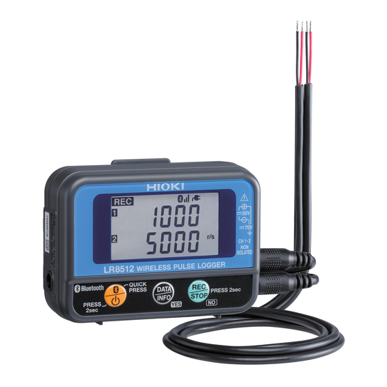
- Page 1 LR8512 LR8513 LR8514 Instruction Manual LR8515 WIRELESS PULSE LOGGER WIRELESS CLAMP LOGGER WIRELESS HUMIDITY LOGGER WIRELESS VOLTAGE/TEMP LOGGER Sept. 2018 Revised edition 6 LR8512B980-06 18-09H GlobalTestSupply www. .com d Quality Products Online at: sales@GlobalTestSupply.c...
-
Page 2: Table Of Contents
Connecting the AC Adapter ...........35 Installing the Strap (optional) ..........36 Connecting Cables ..............37 „ Connecting the L1010 Connection Cable (LR8512) ...... 37 „ Connecting the clamp sensor (LR8513) ......... 38 „ Connecting the temperature and humidity sensor (LR8514) ..48... - Page 3 Contents Using the LR8410 as a Unit Real-time Measurement Using the LR8410 ......49 ® Performing Real-time Measurement Using a Windows PC ..50 Collecting Measurement Data Using a Windows ® 4.1 Software Specifications ............51 „ System requirements ............... 51 „ Function specifications ..............52 4.2 Measurement Workflow ............53 Installing the Software ............55 „...
- Page 4 Contents Sending/Receiving the Setting Conditions ......94 „ Sending the settings ................ 94 „ Receiving the settings ..............95 Starting and Stopping Measurement and Monitoring ..96 „ Starting and stopping measurement ..........96 „ Starting and stopping status monitoring ........97 „...
- Page 5 5.11 Performing Wireless Logger Maintenance ......143 „ Setting the clock................144 „ Checking the version number ............144 Specifications LR8512 Wireless Pulse Logger ...........145 LR8513 Wireless Clamp Logger .........150 LR8514 Wireless Humidity Logger ........156 LR8515 Wireless Voltage/Temp Logger ......161 Z2010, Z2011 Humidity Sensor ...........167 Maintenance and Service Repair, Inspection, and Cleaning ........169...
- Page 6 Contents Disposal ................174 „ Removing lithium batteries ............174 Appendix Appx.1 „ Measurement value recording ..........Appx.1 „ Recording interval and recording time ........Appx.4 „ Target collection time .............. Appx.4 „ Initial setting list ............... Appx.5 GlobalTestSupply www. .com Find Quality Products Online at: sales@GlobalTestSupply.com...
-
Page 7: Introduction
Introduction Introduction Thank you for purchasing the HIOKI LR8512 Wireless Pulse Logger, LR8513 Wireless Clamp Logger, LR8514 Wireless Humidity Logger, or LR8515 Wireless Voltage/Temp Logger. To obtain maximum performance from the product, please read this manual first, and keep it handy for future reference. -
Page 8: Verifying Package Contents
In particular, check the accessories, panel keys, and connectors. If damage is evident, or if it fails to operate according to the specifications, contact your authorized Hioki distributor or reseller. Check the package contents as follows. Instrument Common accessories LR8512 ×... -
Page 9: X84; Options
Verifying Package Contents Options The following options are available for the LR8512, LR8513, LR8514, and LR8515. Contact your authorized Hioki distributor or reseller when ordering. Common options Z2003 AC Adapter (power cord attached) Z5004 Magnetic Strap Z5020 Magnetic Strap LR8512 Option ... - Page 10 Verifying Package Contents LR8514 Option Z2010 Humidity Sensor (Length including the sensor: Approx. 50 mm) Z2011 Humidity Sensor (Cable length: Approx. 1.5 m) Supported instrument LR8410 Wireless Logging Station (Supported for software version 1.30 and later) GlobalTestSupply www.
-
Page 11: Safety Notes
Safety Notes Safety Notes This instrument is designed to conform to IEC 61010 Safety Standards, and has been thoroughly tested for safety prior to shipment. However, using the instrument in a way not described in this manual may negate the provided safety features. Before using the instrument, be certain to carefully read the following safety notes. - Page 12 Safety Notes Symbols affixed to the instrument Indicates cautions and hazards. When the symbol is printed on the instrument, refer to a corresponding topic in the Instruction Manual. Indicates a grounding terminal. Indicates DC (Direct Current). Symbols for various standards Indicates the Waste Electrical and Electronic Equipment Directive (WEEE Directive) in EU member states.
- Page 13 Safety Notes Accuracy We define measurement tolerances in terms of rdg. (reading) and dgt. (digit) values, with the following meanings: (Maximum display value or scale length/range) f.s. The maximum displayable value or scale length. This is usually the name of the currently selected range.
-
Page 14: Usage Notes
Usage Notes Usage Notes Follow these precautions to ensure safe operation and to obtain the full benefits of the various functions. ® Bluetooth This instrument and the LR8410 use radio waves of a band frequency of 2.4 GHz. No radio station license is required to use this product, however, be aware of the following. - Page 15 Usage Notes Check before use Verify that it operates normally to ensure that no damage occurred during storage or shipping. If you find any damage, contact your authorized Hioki distributor or reseller. Installation WARNING Installing the instrument in inappropriate locations may cause a malfunction of the instrument or may give rise to an accident.
- Page 16 Usage Notes Handling of this instrument CAUTION Avoid any vibration or impact to prevent damage to the instrument during transportation and handling. Be especially careful regarding the impact by a fall. This instrument may cause interference if used in residential areas. Such use must be avoided unless the user takes special measures to reduce electromagnetic emissions to prevent interference to the reception of radio and television broadcasts.
- Page 17 Usage Notes Before turning on the power CAUTION • When operating the instrument using a UPS (uninterruptible power supply) or DC-AC inverter, do not use any square-wave and pseudo sine- wave UPS or DC-AC inverter. Doing so may damage the instrument. •...
- Page 18 • To prevent damage to the instrument or electric shocks, make sure to use the battery cover screw (screw with a spring) that is attached at the time of shipment. If you lose the screw or spring or find any damage, contact your authorized Hioki distributor or reseller. GlobalTestSupply www.
- Page 19 Usage Notes CAUTION Poor performance or damage from battery leakage could result. Observe the cautions listed below. • Do not mix new and old batteries, or different types of batteries. • Be careful to observe the battery polarity during installation. Poor performance or damage from battery leakage could result.
- Page 20 30 V AC rms or 60 V DC Non-isolated LR8512 0 to 50 V DC (between each analog (GND common) input channel and chassis) 30 V AC rms or 60 V DC LR8515 ±50 V DC...
- Page 21 Usage Notes WARNING The power supply ground and input terminals (-) are common and not isolated. When using an external power supply, use an isolated external power supply or connect the wires so that there is no potential difference between the ground of the external power supply and the object to be measured to prevent damage to the instrument or electric shocks.
- Page 22 Usage Notes Handling of clamp sensor DANGER Connect the clamp sensor to the LR8513 and then to the live measurement wire. Observe the following to avoid short circuits and electric shocks. • When the clamp sensor is opened, do not allow the metal part of the clamp to short between the 2 wires, and do not use it over bare conductors.
- Page 23 Usage Notes DANGER • Do not allow the clamp sensor to touch beyond a barrier. • The maximum input current of the clamp sensor is as follows. (At 45 to 66 Hz) Model name Clamp sensor Maximum input current 9669 1000 A 9695-02 60 A...
- Page 24 Usage Notes WARNING • This instrument measures live wires. To avoid electric shocks when measuring live wires, wear appropriate protective gear, such as insulated rubber gloves, boots and a safety helmet. • To avoid electric shocks, disconnect the clamp from the object to be measured, open the cover, and then replace the batteries.
- Page 25 Usage Notes CAUTION • Do not excessively tighten the screw of the output terminal for the 9695- 02 Clamp On Sensor. The appropriate torque is 0.5 N•m. • Do not input current exceeding the specified measurement range. Doing so may damage the instrument. •...
- Page 26 Usage Notes Handling of temperature and humidity sensor CAUTION • The temperature and humidity sensor is not dustproof or waterproof. Do not use the sensor in locations where it may be exposed to dust or water. It may cause a malfunction of the instrument. •...
-
Page 27: For Customers Who Are Using The Lr8410 Wireless Logging Station
The firmware version for the LR8410 is displayed on the system screen. The latest version can be downloaded from our website. For details on how to upgrade the software, see our website or check with your authorized Hioki distributor or reseller. -
Page 28: Instrument Version
Instrument Version Instrument Version The Wireless Logger Collector can be used on the instrument software version 1.20 or later. A version older than 1.20 needs to be updated. The software can be updated in ® Wireless Logger Collector (Windows PC version). (p. 1 07) If the software version is older than 1.20, a communication error (protocol error) occurs in any communications attempted between the instrument and Wireless Logger Collector. -
Page 29: Overview
This is a compact wireless logger that is capable of measurement, display, and recording. Model Description LR8512 Wireless Pulse Logger • Counts pulses and records an integrated value. • Measures the revolution and logic ON/OFF signal. LR8513 Wireless Clamp Logger •... -
Page 30: Parts Names And Functions
(p. 3 8) (p. 3 5) Right side Bottom side LR8515 LR8512, LR8514 Connection terminal For LR8512, connect the L1010 Connection Cable. Connection terminal For LR8514, connect the Connect the input cable or thermocouple. temperature and humidity sensor. (p. 4 8) (p. ... - Page 31 Parts Names and Functions Display Display Description Display Description Channel (CH) Lit: Average recording mode Blinking: During monitoring Blinking: Maximum recording MODE mode (LR8513 Wireless Clamp Maximum value Logger only) Minimum value Average value Lit: Bluetooth ON Blinking: Bluetooth OFF Data number (The power saving function is Unit number...
-
Page 32: Display Configuration Example
Display Configuration Example 1.3 Display Configuration Example CH1/CH2 Measurement value *1, *2, *4, *7, *8, *10 *1, *2, *5, *7, *8, *10 CH1 Statistical value (MAX/MIN) Screen Time *1, *2, *5, *7, *8, *10 CH2 Statistical value (MAX/MIN) change (Top: Hour and minute/Bottom: Second) Date *1, *2, *4, *6, *7, *8, *10 CH1/CH2 Statistical value (Average) - Page 33 Display Configuration Example *7 If the measurement value (pulse value) of pulse measurement (instant/integrating mode, scaling OFF) is over 10,000, it is displayed at the top and bottom. If the measurement value is over 10,000,000, any value less than 1,000 is not displayed. *8 The screen for the channel for which the temperature and humidity measurement is set to OFF is not displayed.
- Page 34 Display Configuration Example GlobalTestSupply www. .com Find Quality Products Online at: sales@GlobalTestSupply.com...
-
Page 35: Preparation For Measurements
Before using the instrument for the first time, verify that it operates normally to ensure that no damage occurred during storage or shipping. If you find any damage, contact your authorized Hioki distributor or reseller. “Before sending the instrument for repair” (p.171) -
Page 36: Inserting/Replacing Batteries
Inserting/Replacing Batteries 2.2 Inserting/Replacing Batteries Insert two LR6 Alkaline batteries. Before measurements, check that the battery level is sufficient. When the battery charge is low, replace the batteries. CAUTION Stop measurement and then replace the batteries. Replacing the batteries during measurement may damage the data. IMPORTANT Batteries The battery indicator display and battery life are based on the use of a new... -
Page 37: X84; Installation (Replacement)
(screw with a spring) that is attached at the time of shipment. If you lose the screw or spring or find any damage, contact your authorized Hioki distributor or reseller. Required items LR6 Alkaline battery × 2, Phillips screwdriver (No. 2) Remove the connection cables. -
Page 38: X84; Battery Indicator Display
2. Model 3. Version number (Example: When the (Example: Version 1.00) LR8512 is used) Battery indicator display Displayed at the upper right corner of the display. Fully charged. As the battery charge diminishes, black charge bars disappear, one by one, from the left of the battery indicator. -
Page 39: X84; Battery Life Indication
The battery life varies depending on the recording interval. In case of the free run function, the battery life is the same as for 1 second regardless of the recording interval setting. (when recording interval setting is more than 2 seconds) LR8512 Wireless Pulse Logger Recording interval 0.1 sec. - Page 40 Inserting/Replacing Batteries LR8515 Wireless Voltage/Temp Logger Recording interval 0.1 sec. 1 sec. 10 sec. 1 min. Real-time measurement Approx. 2 days Approx. 4 days Approx. 7 days Approx. 14 days Bluetooth ON Manual data collection Approx. 3 days Approx. 7 days Approx. 14 days Approx. 20 days Bluetooth ON Manual data collection Approx.
-
Page 41: Connecting The Ac Adapter
When the AC adapter is connected, the following screen is displayed. 1. All indicators on 2. Model 3. Version number (Example: When the (Example: Version 1.00) LR8512 is used) When the AC adapter is used, is lit at the upper right of the display. GlobalTestSupply www. .com Find Quality Products Online at: sales@GlobalTestSupply.com... -
Page 42: Installing The Strap (Optional)
Installing the Strap (optional) 2.4 Installing the Strap (optional) When the optional Z5004/Z5020 Magnetic Strap is attached to the instrument, the magnet can be attached to the wall surface (metal plate). Attach the Z5004 or Z5020 through the strap hole. In order of (1) →... -
Page 43: Connecting Cables
Connecting Cables 2.5 Connecting Cables Connecting the L1010 Connection Cable (LR8512) Connect the connection cable to the LR8512 connection terminal. − used L1010 Connection Cable (length approx. 1.5 m) Red wire: Voltage input (+) − Black wire: Voltage input (-) •... -
Page 44: X84; Connecting The Clamp Sensor (Lr8513)
Connecting Cables Connecting the clamp sensor (LR8513) Connect the clamp sensor to the LR8513 connection terminal. Use the specified clamp sensor. For more details, see the instruction manual supplied with the clamp sensor. Align the BNC connector groove of the clamp sensor with the instrument connector guide and insert it. - Page 45 Connecting Cables Model Clamp sensor CT7631 CT7636 AC/DC Current Sensor CT7642 CT7731 AC/DC Auto-Zero CT7736 Current Sensor CT7742 CT9667-01 CT9667-02 CT9667-03 AC Flexible Current Sensor CT7044 CT7045 CT7046 The 9219 Connection Cord is required in order to connect a compatible clamp sensor. The CM7290 or CM7291 Display Unit and L9095 Output Cord are required in order to connect a compatible clamp sensor.
- Page 46 Connecting Cables Using the CT9691-90, CT9692-90 or CT9693-90 The CT9691-90, CT9692-90, and CT9693-90 are each composed of the CT9691, CT9692, or CT9693 Clamp Sensor and CT6590 Sensor Unit. CT6590 Sensor Unit overview and parts names The CT6590 Sensor Unit is a unit to connect the CT9691, CT9692, and CT9693 Clamp ON AC/DC Sensor to the measuring instrument.
- Page 47 Connecting Cables Measurement procedure Zero adjustment LR8513 0.00 A CT6590 Sensor Unit Supply power to the CT6590 Sensor Unit (battery or AC adapter). There are two power supplies, batteries (accessory) and AC adapter (optional). Use the AC adapter when operating the instrument continuously for a long period of time. Connect the clamp sensor to the CT6590.
- Page 48 Connecting Cables Using the CM7290 or CM7291 The CM7290/CM7291 Display Unit provides a Hioki PL14 output connector and is used by connecting it to a current sensor. Measurement procedure 6 -1 Select the Perform zero- measurement mode adjustment Press and hold...
- Page 49 Connecting Cables Configure the current sensor. -1.Select the measurement mode. AC/DC -2.Select the output mode. -3.Select the output rate. Refer to the table of output rates and corresponding measurement ranges. Start measurement after configuring the LR8513. Once measurement is complete, disconnect the current sensor from the conductor being measured and turn off the LR8513.
- Page 50 Connecting Cables Connecting to a conductor Clamp only one conductor with the clamp sensor for measurement. 9669, 9695-02, CT6500 Clamp On Sensor CT9691-90, CT9692-90, CT9693-90 Clamp On AC/DC Sensor (The figure is for the CT6500.) 9675, 9657-10 Clamp On Leak Sensor (The figure is for the 9675.) •...
- Page 51 Connecting Cables For leak current measurement The 9675, 9657-10 Clamp On Leak Sensor can be used. Clamp the conductor at the center of the clamp core. When the measurement current level is unknown, set the range level to the 5 A range before starting measurement.
- Page 52 Connecting Cables Inspection for areas with insulation deterioration 1. Measure the leak current in the entire circuit and determine whether there is any short-circuit based on a change in the current. Normally leak current is measured with the Class B ground cable of the transformer. Single-phase/3-wire circuit Load Class B...
- Page 53 Connecting Cables For load current measurement Tuck in the conductor at the center of the clamp core. • Any special waveforms like the secondary side of an inverter cannot be measured. • When the measurement current level is unknown, set the range level to the following before starting measurement.
-
Page 54: X84; Connecting The Temperature And Humidity Sensor (Lr8514)
Connecting Cables Connecting the temperature and humidity sensor (LR8514) Attach one or two pieces of Humidity Sensor to the connection terminals of the LR8514 Wireless Humidity Logger. Supported sensors Z2010 Humidity Sensor Length including the sensor: Approx. 50 mm Z2011 Humidity Sensor Cable length: Approx. 1.5 m Right side of instrument Z2010 or Z2011 Humidity Sensor... -
Page 55: Using The Lr8410 As A Unit
3 Using the LR8410 as a Unit Using the LR8410 as a Unit There are two ways. Real-time measurement using the LR8410 LR8410 (Line-of-sight 30 m) ® Real-time measurement using a Windows Windows ® (Logger Utility) LR8410 LAN/USB (Line-of-sight 30 m) communications 3.1 Real-time Measurement Using the LR8410 Turn ON the power of the instrument and the LR8410. -
Page 56: Performing Real-Time Measurement Using A Windows ® Pc
® Performing Real-time Measurement Using a Windows 3.2 Performing Real-time Measurement Using a ® Windows Register the instrument as a unit in the LR8410. (p. 4 9) Install Logger Utility on the Windows ® Logger Utility Start up Logger Utility. The main screen is displayed when Logger Utility starts up. -
Page 57: Windows ® Pc
4 Collecting Measurement Data Using a Windows ® Collecting Measurement Data ® Using a Windows ® Windows • Wireless Logger Collector • Logger Utility (Line-of-sight 30 m) 4.1 Software Specifications System requirements 1 GHz or faster 32-bit or 64-bit processor Memory 1 GB or more of RAM (32-bit) or 2 GB or more of RAM (64-bit) Display... -
Page 58: X84; Function Specifications
Software Specifications Function specifications Number of allowable 100 units registrations Settings Measurement settings can be edited/copyed/initialized and sent/ received. Measurement control Measurement can be started and stopped. Monitoring function The status can be monitored. The status can be monitored repeatedly and periodically (10 minutes to 1 day). -
Page 59: Measurement Workflow
Measurement Workflow 4.2 Measurement Workflow Install the instrument referring to “Preparation for Measurements” (p. 2 9). Install the software on the Windows ® • Wireless Logger Collector • Logger Utility Register the instrument in Wireless Logger Collector (up to 100 units). (p. ... - Page 60 Measurement Workflow Send the measurement conditions to the instrument. (p. 9 4) Start measurement. (p. 9 6) You can also start measurement by holding down this button. Collect measurement data using Wireless Logger Collector. (p. 9 9) Measurement data can be collected during measurement and after measurement stop.
-
Page 61: Installing The Software
Installing the Software 4.3 Installing the Software Installation Install the software according to the following procedure. Displayed messages and operations may be different depending on the operating system or settings. Close all the software that is running. IMPORTANT If any anti-virus software is running, make sure to close it before starting the installation. -
Page 62: X84; Startup Procedure
Installing the Software Startup procedure ® For Windows 7/Windows Vista [All Programs] - [HIOKI] - [Logger Utility] - From the Windows Start menu, click [Wireless Logger Collector]. For Windows 8 From the Start window, display the [Apps] view and click [HIOKI] - [Wireless Logger Collector]. -
Page 63: X84; Uninstallation
[Programs and Features]. [Uninstall or change a program] screen is displayed. Double-click [HIOKI Logger Utility] in the list of installed programs. As the measurement data and setting files remain as they are, delete them manually if they are not needed. GlobalTestSupply www. -
Page 64: Display Configuration
Display Configuration 4.4 Display Configuration The main screen is displayed when the application starts up. Name Description Application button Displays the option menu, etc. Quick access tool bar Right-click and customize the Ribbon bar. Ribbon Allows you to operate or edit the items displayed in the list. Navigation bar •... -
Page 65: Basic Operation Procedure
Basic Operation Procedure 4.5 Basic Operation Procedure Operation flow Select one of the following categories from the Navigation bar. [Register/Settings], [Measurement/Monitoring], [Collection/Browse], [Maintenance] Select a group and wireless logger from the wireless logger list (tree display). Select the item to be displayed from the wireless logger/channel/file list (list display). -
Page 66: X84; Selecting Multiple Wireless Loggers
Basic Operation Procedure Selecting multiple wireless loggers Search/Select From all the registered wireless loggers, communicative wireless loggers are searched for and selected automatically. • This button may not be used depending on the PC specifications. • This button may not be selected depending on the communications with the wireless logger. -
Page 67: Registering/Deleting A Wireless Logger
Registering/Deleting a Wireless Logger 4.6 Registering/Deleting a Wireless Logger Registering a wireless logger Register a wireless logger in Wireless Logger Collector. Up to 100 wireless loggers can be registered. IMPORTANT Some functions of Wireless Logger Collector may not be used depending on the PC specifications. - Page 68 Registering/Deleting a Wireless Logger Registration Select [Register/Settings] - [Register/remove device] of the Navigation bar. [Register/remove device] dialog box is displayed. Click [Search]. The nearby wireless loggers or wireless loggers that have been connected are displayed in the list on the left. (COM ports are displayed if a third party Bluetooth stack is used.) Select the wireless logger(s) to be registered from the list on the left (multiple units can be selected).
- Page 69 Registering/Deleting a Wireless Logger ® • When a Windows standard Bluetooth stack is used, the model name and serial number are displayed in “Found devies”. ® To check whether Windows standard Bluetooth stack is enabled, select [Control Panel] - [Device Manager], open [Bluetooth Radios], and then check if...
-
Page 70: X84; Deleting A Wireless Logger
Registering/Deleting a Wireless Logger Deleting a wireless logger Delete the wireless logger that is registered in Wireless Logger Collector (registration cancel). Select [Register/Settings] [Register/remove device] of the Navigation bar. [Register/remove device] dialog box is displayed. Select the wireless logger(s) to be deleted from the list on the right (multiple units can be selected). -
Page 71: X84; Grouping Wireless Loggers
Registering/Deleting a Wireless Logger Grouping wireless loggers Wireless loggers can be grouped and managed. Grouping is useful for managing multiple wireless loggers. Groups can be added to the layered structure. Procedure to create a group From [List] (the wireless logger list [tree display]), select [Computer] the group for which a new group is to be created. - Page 72 Registering/Deleting a Wireless Logger Procedure to move a group From [List] (the wireless logger list [tree display]), drag the wireless logger to be moved using the left key of the mouse and drop it on the target group. Drag and drop Procedure to delete a group From [List]...
-
Page 73: Setting Measurement Conditions
Setting Measurement Conditions 4.7 Setting Measurement Conditions Set the measurement conditions for wireless loggers. Select [Register/Settings] from the Navigation bar. Select the target wireless logger. Click [Open] on the Ribbon bar. The settings dialog box is displayed. GlobalTestSupply www. .com Find Quality Products Online at: sales@GlobalTestSupply.com... -
Page 74: X84; Setting Measurement
Setting Measurement Conditions Setting measurement Recording Interval Allows you to set the interval to import data. Settings: 0.1 sec., 0.2 sec., 0.5 sec., 1 sec., 2 sec., 5 sec., 10 sec., 20 sec., 30 sec., 1 min., 2 min., 5 min., 10 min., 20 min., 30 min., 1 hour. Recording interval •... - Page 75 Setting Measurement Conditions Title Comment Allows you to set the title comment. (Up to 40 single-byte characters) The characters entered are converted to the following symbols. (Superscript) (Superscript) μ ° ε Scheduled Record Start Measurement can be started at the specified time. If the current time has passed the preset time, measurement is not started.
-
Page 76: X84; Setting The Channel
Setting Measurement Conditions Setting the channel The channel to be set is switched. Measurement Allows you to set measurement to ON/OFF. Settings: Does not perform measurement. Performs measurement. Comment Allows you to set the channel comment. (Up to 40 single-byte characters) The characters entered are converted to the following symbols. - Page 77 Setting Measurement Conditions LR8512 Wireless Pulse Logger Making settings for integrated measurement The number of integrated pulses output from the integrated power meter or flow meter is measured. : Select the channel to be set and check the Measurement checkbox []...
- Page 78 Setting Measurement Conditions Select the chattering prevention filter setting. Settings: Turns OFF the chattering prevention filter. Turns ON the chattering prevention filter. For mechanical contact (relay) output signals, a count error due to chattering can be prevented. • With the scaling function, the number of integrated pulses can be converted to a physical quantity (Wh, VA, etc.) for the object to be measured.
- Page 79 Setting Measurement Conditions Select the measurement reference (slope). Settings: Rise Measures the rotation speed based on LOW to HIGH. Fall Measures the rotation speed based on HIGH to LOW. HIGH Detection level Select the HIGH/LOW reference value (detection level). Settings: Determines 1.0 V or higher to be HIGH, 0 V to 0.5 V to be LOW.
- Page 80 Setting Measurement Conditions Making settings for logic measurement Logic signals are measured. : Select the channel to be set and check the Measurement checkbox [] (ON). Select [Logic]. Select the HIGH/LOW reference value (detection level). Settings: Determines 1.0 V or higher to be HIGH, 0 V to 0.5 V to be LOW. Determines 4.0 V or higher to be HIGH, 0 V to 1.5 V to be LOW.
- Page 81 Setting Measurement Conditions LR8513 Wireless Clamp Logger Making settings for current measurement The current is measured. : Select the channel to be set and check the Measurement checkbox [] (ON). Select the clamp sensor to be used. Settings: 9675, 9657-10, 9695-02, CT6500, 9669, CT9691-90, CT9692-90, CT9693-90, CT7631* CT7636*...
- Page 82 Setting Measurement Conditions CT9692-90 20 A, 200 A CT9693-90 200 A, 2000 A CT7631 10 A, 100 A CT7636 20 A, 200 A CT7642 200 A, 2000 A CT7731 10 A, 100 A CT7736 20 A, 200 A CT7742 200 A, 2000 A CT9667 500 A, 5000 A CT7044...
- Page 83 Setting Measurement Conditions LR8514 Wireless Humidity Logger Making settings for temperature and humidity measurement The temperature and humidity are measured using the Z2010/Z2011 Temperature and Humidity Sensor. : Select the channel to be set and check the Measurement checkbox [] (ON).
- Page 84 Setting Measurement Conditions LR8515 Wireless Voltage/Temp Logger Making settings for voltage measurement The channel is set for performing voltage measurement. : Select the channel to be set and check the Measurement checkbox [] (ON). Select [Voltage]. Select the measurement range according to the object to be measured. Settings: 50 mV, 500 mV, 5 V, 50 V When measuring the output from a measurement instrument...
- Page 85 Setting Measurement Conditions Making settings for temperature (thermocouple) measurement The temperature is measured using a thermocouple. : Select the channel to be set and check the Measurement checkbox [] (ON). Select [Thermocouple]. Select the thermocouple type. Settings: Select the disconnection detection setting. Settings: Does not perform disconnection detection.
- Page 86 Setting Measurement Conditions Select the reference junction compensation setting. Implements reference junction compensation inside the instrument. This setting is made when a thermocouple (or compensating lead wire) Internal is connected directly to the instrument. The measurement accuracy is the value obtained when the temperature measurement accuracy and reference junction compensation accuracy are added.
-
Page 87: X84; Setting Scaling (As Needed)
Setting Measurement Conditions Setting scaling (as needed) The input value can be converted to a physical quantity of the object to be measured from voltage to current, etc. Normal display (OFF) With scaling Setting scaling for voltage, current, temperature, humidity, and rotation speed measurement Select the display format of the scaling value. - Page 88 Setting Measurement Conditions Set the unit to be converted (up to 7 single-byte characters). The characters entered are converted to the following symbols. (Superscript) (Superscript) μ ° ε When Ratio is selected, set the conversion ratio and offset. When 2 Points is selected, set the value for 2 points before and after conversion.
- Page 89 Setting Measurement Conditions Setting scaling for integrated measurement The number of integrated pulses can be converted to a physical quantity (Wh, VA, etc.) for the object to be measured. For a pulse output instrument, the physical quantity per pulse or the number of pulses per basic unit (example: 1 kWh, 1 L, 1 m ) is defined.
- Page 90 Setting Measurement Conditions Scaling setting example When integrating the number of pulses with a 50,000 pulse/kWh power meter connected: Scaling decimal Unit kWh 1 kWh = 50,000 pulses When integrating the number of pulses with a 10 L/pulse flow meter connected: Scaling decimal Unit L 1 pulse = 10 L...
-
Page 91: X84; Setting The Alarm Function (As Needed)
Setting Measurement Conditions Setting the alarm function (as needed) Make the alarm settings. Alarm Settings Allows you to set the alarm function to ON/OFF. Settings: Alarm function OFF Alarm function ON Hold Alarm Allows you to set the alarm hold function to ON/OFF. Whether or not to hold the alarm is set. - Page 92 Setting Measurement Conditions Setting the alarm for each channel Allows you to set the alarm conditions for each channel. Alarm settings other than logic Alarm Method Settings: Does not perform alarm judgment. Level When the specified level is reached, judges it to be an alarm. When a value is inside of the specified upper and lower limit range, Window In judges it to be an alarm.
- Page 93 Setting Measurement Conditions Alarm settings for logic Bit Pattern Settings: Does not perform judgment. When any of the conditions that are set between channels are met, judges it to be an alarm. When all of the conditions that are set between channels are met, judges it to be an alarm.
-
Page 94: X84; Setting The Power Saving Function (As Needed)
Setting Measurement Conditions Setting the power saving function (as needed) Setting the Bluetooth module power to OFF can save the battery life. Schedule The method to turn ON/OFF the Bluetooth module power is set. Settings: Does not turn ON/OFF the Bluetooth module power. Every Day Turns ON the Bluetooth module power at the specified time. -
Page 95: X84; Setting The Environment
Setting Measurement Conditions Setting the environment Prevent a wrong key operation of the body A confirmation message can be displayed at the time of measurement start, stop, and power OFF to prevent operational errors. Settings: Does not display a confirmation message. ... -
Page 96: X84; Communications
Setting Measurement Conditions Free Run The measurement value is indicated every 1 second while measurement is stopped. (the data is not saved in the memory). The measurement value is saved in the memory every recording interval and indicated every 1 second regardless of recording interval setting while measuring. (when the setting of recording interval is less than 1 second, the measurement value is indicated every recording interval) Settings:... - Page 97 Setting Measurement Conditions Identification name change You can name the wireless logger to be identified (up to 16 single-byte characters). The characters entered are converted to the following symbols. (Superscript) (Superscript) μ ° ε Bluetooth COM The communications port setting cannot be changed. •...
-
Page 98: X84; Copying The Settings
Setting Measurement Conditions Copying the settings The settings of a particular wireless logger can be copied to another wireless logger. The settings of a particular channel can also be copied to another channel. Some settings cannot be copied if the wireless logger type is different. 2, 4 Select [Register/Settings]... -
Page 99: X84; Initializing The Settings
Setting Measurement Conditions Initializing the settings The settings are restored to the default values. (p. A ppx.5) Select [Register/Settings] from the Navigation bar. Select the target wireless logger. Click [Clear]. GlobalTestSupply www. .com Find Quality Products Online at: sales@GlobalTestSupply.com... -
Page 100: Sending/Receiving The Setting Conditions
Sending/Receiving the Setting Conditions 4.8 Sending/Receiving the Setting Conditions Sending the settings The setting conditions edited in Wireless Logger Collector are sent to and set for wireless loggers using wireless communications. Select [Register/Settings] from the Navigation bar. Select the target wireless logger. Press [Send]. -
Page 101: X84; Receiving The Settings
Sending/Receiving the Setting Conditions Receiving the settings The settings of the current wireless logger are received by Wireless Logger Collector using wireless communications. Select [Register/Settings] from the Navigation bar. Select the target wireless logger. Press [Receive]. When the settings are received, the settings of the corresponding unit are all overwritten. -
Page 102: Starting And Stopping Measurement And Monitoring
Starting and Stopping Measurement and Monitoring 4.9 Starting and Stopping Measurement and Monitoring Starting and stopping measurement Wireless logger measurement is started and stopped. Select [Measurement/Monitoring] from the Navigation bar. Select the target wireless logger. Press [Start] or [Stop]. When measurement start is preset, measurement does not start until the preset time. -
Page 103: X84; Starting And Stopping Status Monitoring
Starting and Stopping Measurement and Monitoring Starting and stopping status monitoring The wireless logger status is periodically monitored. The status is periodically monitored until the status monitoring is stopped once the monitoring interval is set. (p. 1 10) Items to be monitored: Measurement status, latest measurement data, battery level, wireless signal level The monitoring result is displayed in each line of the list. -
Page 104: X84; Starting And Stopping Value Monitoring
Starting and Stopping Measurement and Monitoring Starting and stopping value monitoring Select [Measurement/Monitoring] from the Navigation bar. Select the target wireless logger. Press [Open] on the Ribbon bar. The value monitor screen is displayed. Press (connect) button on the tool bar. The value monitor is started. -
Page 105: Collecting Measurement Data
Collecting Measurement Data 4.10 Collecting Measurement Data Starting and stopping data collection Measurement data is collected from wireless loggers. Measurement data can be collected even while wireless loggers are being measured. Measurement data is periodically collected until the data collection is stopped once the collection interval is set. -
Page 106: Browsing/Analyzing Measurement Data
Browsing/Analyzing Measurement Data 4.11 Browsing/Analyzing Measurement Data Browsing measurement data Collected measurement data can be displayed in a waveform using the Logger Utility. 2, 3, 4 Select [Collection/Browse] from the Navigation bar. Select the target wireless logger. Double-click the target wireless logger in the list using the mouse. The list switches to the collected measurement data (file) list. -
Page 107: X84; Exporting Measurement Data
Browsing/Analyzing Measurement Data Exporting measurement data Measurement data can be output in various formats. Use this function to analyze ® ® measurement data using software like Microsoft Excel 2, 3, 4 Select [Collection/Browse] from the Navigation bar. Select the target wireless logger. Double-click the target wireless logger in the list using the mouse. - Page 108 Browsing/Analyzing Measurement Data Select the file type. When you want to combine multiple measurement data files to 1 file, please choose [Logger Utility General-purpose Data Format]. Settings: Compatible Logger Utility Format, Logger Utility General-purpose Data Format [File Combination], LR5000 Format and Smart Site Format, LR5000 Format, CSV (Comma), Text (delineated by semicolon), Text (delineated by space), Text (delineated by tab) (For CSV or text format) Make detail settings.
-
Page 109: X84; Deleting Measurement Data
Browsing/Analyzing Measurement Data Deleting measurement data Collected measurement data can be deleted. Select [Collection/Browse] from the Navigation bar. Select the target wireless logger. Double-click the target wireless logger in the list using the mouse. The list switches to the collected measurement data (file) list. Select the measurement data to be deleted from the list. -
Page 110: Performing Wireless Logger Maintenance
Performing Wireless Logger Maintenance 4.12 Performing Wireless Logger Maintenance Setting the clock ® The wireless logger clock is set according to the Windows PC clock. Select [Maintenance] from the Navigation bar. Select the target wireless logger. Press [Adjust Clock]. The clock cannot be set during wireless logger measurement and monitoring. GlobalTestSupply www. -
Page 111: X84; Self-Diagnosis
Select the target wireless logger. Press [Self-Test]. Self-diagnosis takes approximately 2 minutes. If the self-diagnosis result is displayed as [Error], the instrument needs to be repaired or inspected. Contact your authorized Hioki distributor or reseller. GlobalTestSupply www. .com Find Quality Products Online at:... -
Page 112: X84; Checking The Version Number
Performing Wireless Logger Maintenance Checking the version number The firmware version of wireless loggers is checked. Select [Maintenance] from the Navigation bar. Select the target wireless logger. Press [Version Check]. GlobalTestSupply www. .com Find Quality Products Online at: sales@GlobalTestSupply.com... -
Page 113: X84; Updating The Firmware Version
Performing Wireless Logger Maintenance Updating the firmware version The firmware version of wireless loggers is updated. Select [Maintenance] from the Navigation bar. Select the target wireless logger. Press [Version Upgrade]. The latest update file version can be downloaded from our Internet website. Execute [Import Version Upgrade File] in the menu to load the downloaded file... -
Page 114: Convenient Functions
Convenient Functions 4.13 Convenient Functions Column The description to be displayed in the list (wireless logger/channel/file) can be selected. Font Size The size of letters in the list can be changed. Settings Small, Standard, Medium, Large, Extra Large Language The display language for the application is switched. Restart the application to reflect the change. - Page 115 Convenient Functions Caption Bar, Output Window, Status Bar The window display/non-display status is switched. Version Information The version information of the application is displayed. Import Data File to Application Measurement files (in LUW format) exported through the Android version of Wireless Logger Collector are imported to Wireless Logger Collector.
- Page 116 Convenient Functions Option The optional functions are set. Set the number of simultaneous connections. Set the monitor interval. Set the collection interval. Max. Connectable Devices Settings (*: Default settings) to 7 device(s) The number of simultaneous connections may be limited depending on the PC environment.
-
Page 117: Collecting Measurement Data Using An Android
5 Collecting Measurement Data Using an AndroidTM Terminal Collecting Measurement Data Using an Android Terminal • Android tablet Windows ® • Android smartphone (Line-of-sight 30 m) 5.1 Software Specifications System requirements Android OS 4.0.3 or later Recommended 7 inches or larger display size Communication Bluetooth 2.1+EDR or higher... -
Page 118: Measurement Workflow
Measurement Workflow 5.2 Measurement Workflow Install the instrument referring to “Preparation for Measurements” (p. 2 9). Install Wireless Logger Collector on the Android terminal. (p. 1 15) Wireless Logger Collector Register the instrument in Wireless Logger Collector (up to 100 units). (p. ... - Page 119 Measurement Workflow Start measurement. (p. 1 33) You can also start measurement by holding down this button. Collect measurement data using Wireless Logger Collector. (p. 1 36) GlobalTestSupply www. .com Find Quality Products Online at: sales@GlobalTestSupply.com...
- Page 120 Measurement Workflow Export the measurement data to a file. (p. 1 39) Copy the exported file onto the Windows PC. (p. 1 40) ® USB cable Analyze the data on the Windows ® GlobalTestSupply www. .com Find Quality Products Online at: sales@GlobalTestSupply.com...
-
Page 121: Installing The Software
Installing the Software 5.3 Installing the Software Installation Go to “Google Play Store” and download Wireless Logger Collector. [Play Store] in the application Tap the [Search] button. screen. [Play Store] may not be available on some models. [Wireless Logger Collector] Enter a key word. -
Page 122: X84; Startup Procedure
Installing the Software Startup procedure In the application screen, tap [Wireless Logger Collector]. Uninstallation The application can be removed from “Google Play Store” or the [Settings] - [Apps] screen. IMPORTANT When the application is uninstalled, the wireless logger registration information, settings, and collected measurement data are erased. -
Page 123: Display Configuration
Display Configuration 5.4 Display Configuration Main screen Wireless logger search and registration Wireless logger monitoring status Menu buttons Registered wireless loggers Group name Operation buttons • Settings • Measurement • Collection • Browse Back GlobalTestSupply www. .com Find Quality Products Online at: sales@GlobalTestSupply.com... - Page 124 Display Configuration Monitor screen Wireless logger status Latest measurement data Trend waveform (Update interval: 1 second, up to 100 data) GlobalTestSupply www. .com Find Quality Products Online at: sales@GlobalTestSupply.com...
- Page 125 Display Configuration Settings screen Discards the changed settings. Confirms and saves the changed settings. Receives all settings from the selected wireless logger. Sends all settings to the selected wireless logger. GlobalTestSupply www. .com Find Quality Products Online at: sales@GlobalTestSupply.com...
- Page 126 Display Configuration Browse screen Title comment Collection date and time Number of data Measurement start date and time GlobalTestSupply www. .com Find Quality Products Online at: sales@GlobalTestSupply.com...
- Page 127 Display Configuration Graph screen Displayed Jump to the waveforms can specified time. be expanded or compressed along the horizontal axis. The display range can be adjusted. Select channel for gauge display. GlobalTestSupply www. .com Find Quality Products Online at: sales@GlobalTestSupply.com...
-
Page 128: Registering/Deleting A Wireless Logger
Registering/Deleting a Wireless Logger 5.5 Registering/Deleting a Wireless Logger Registering a wireless logger Register a wireless logger in Wireless Logger Collector. Up to 100 wireless loggers can be registered. The search result list is displayed. It may take several tens of seconds to search for wireless loggers. -
Page 129: X84; Deleting A Wireless Logger
Registering/Deleting a Wireless Logger Deleting a wireless logger Units that are registered in Wireless Logger Collector are deleted (registration cancel). Tap the menu button. [Remove Logger]. Select the group to which the unit to be deleted belongs. Select the unit to be deleted. IMPORTANT When wireless loggers are deleted (registration canceled), the settings and collected measurement data are also deleted. -
Page 130: X84; Grouping Wireless Loggers
Registering/Deleting a Wireless Logger Grouping wireless loggers Wireless loggers can be grouped and managed. Grouping is useful for managing multiple wireless loggers. Procedure to create a group Tap the menu button. [Add Group]. Enter a new group name. A new group is now created at the very bottom of the list. GlobalTestSupply www. - Page 131 Registering/Deleting a Wireless Logger Changing the group Tap the menu button. [Change Group]. Select the current group. Select the wireless logger to be moved. Select the group to which the wireless logger is to be moved. Procedure to delete a group Tap the menu button.
-
Page 132: Setting Measurement Conditions
Setting Measurement Conditions 5.6 Setting Measurement Conditions Set the measurement conditions for wireless loggers. For details on settings, see “4.7 Setting Measurement Conditions” (p. 67). [Settings] button. Tap the wireless logger for which the settings are to be changed. The settings screen is displayed. Set the measurement conditions. -
Page 133: X84; Setting Measurement
Setting Measurement Conditions Setting measurement Title Comment Allows you to set the title comment. (up to 40 single-byte characters) Identifier Name You can name the unit to be identified (up to 16 single-byte characters). Recording Interval Allows you to set the interval to import data. Continuous Recording Allows you to set a processing method when the memory is full. -
Page 134: X84; Setting The Channel
Setting Measurement Conditions Setting the channel Set the input, scaling, and alarm for each channel. Settings screen Scaling settings screen Alarm settings screen GlobalTestSupply www. .com Find Quality Products Online at: sales@GlobalTestSupply.com... -
Page 135: X84; Advance Settings
Setting Measurement Conditions Advance settings Record Schedule Scheduled Record Start Measurement can be started at the specified time. Scheduled Record Stop Measurement can be stopped at the specified time. Power Save The time to turn ON/OFF the Bluetooth module power is set. Setting Schedule the Bluetooth module power to OFF can save the battery life. -
Page 136: X84; Initializing The Settings
Setting Measurement Conditions The measurement value is indicated every 1 second while measurement is stopped. (the data is not saved in the memory) The measurement value is saved in the memory and indicated Free Run every 1 second regardless of recording interval setting while measuring. -
Page 137: Sending/Receiving The Setting Conditions
Sending/Receiving the Setting Conditions 5.7 Sending/Receiving the Setting Conditions Sending the settings The settings edited on the applications are sent to and set for wireless loggers using wireless communications. Tap the [Settings] button. Tap the wireless logger to be edited. The settings screen is displayed. -
Page 138: X84; Receiving The Settings
Sending/Receiving the Setting Conditions Receiving the settings The settings of the current wireless logger are received by the application using wireless communications. Tap the [Settings] button. Tap the wireless logger to which the settings are to be sent. The settings screen is displayed. Tap the [Receive] button. -
Page 139: Starting And Stopping Measurement And Monitoring
Starting and Stopping Measurement and Monitoring 5.8 Starting and Stopping Measurement and Monitoring Starting and stopping measurement Wireless logger measurement is started and stopped. Tap the [Measure] button. Tap the wireless logger for which measurement is to be started or stopped. The menu is displayed. -
Page 140: X84; Starting And Stopping Monitoring
Starting and Stopping Measurement and Monitoring Starting and stopping monitoring Checking the latest status of wireless loggers The current status of wireless loggers can be checked. The measurement status, power status (battery level), and wireless signal level can be checked. at the top of the screen. - Page 141 Starting and Stopping Measurement and Monitoring Checking the latest data of wireless loggers The latest measurement data of the wireless loggers that are being measured can be checked in the waveform and value formats. This is useful for checking measurement before installation.
-
Page 142: Collecting Measurement Data
Collecting Measurement Data 5.9 Collecting Measurement Data Measurement data is collected from wireless loggers. Starting and stopping data collection Measurement data is collected from wireless loggers. Measurement data can also be collected during measurement. Tap the [Collection] button. Tap the wireless logger from which the measurement data is to be collected. -
Page 143: Browsing/Analyzing Measurement Data
Browsing/Analyzing Measurement Data 5.10 Browsing/Analyzing Measurement Data Browsing measurement data The collected measurement data can be displayed on the screen. GlobalTestSupply www. .com Find Quality Products Online at: sales@GlobalTestSupply.com... - Page 144 Browsing/Analyzing Measurement Data Tap the [Browse] button. Tap the wireless logger for which the measurement data is to be browsed. The browsing screen is displayed. (p. 1 20) Tap the collected measurement data to be displayed. The menu is displayed. [Show Graph].
-
Page 145: X84; Exporting Measurement Data
Browsing/Analyzing Measurement Data Exporting measurement data ® The collected measurement data can be output to a file to use it on the Windows PC, etc. Tap the [Browse] button. Tap the wireless logger for which the measurement data is to be browsed. The browsing screen is displayed. - Page 146 A LUW file can be browsed/analyzed using the supplied Logger Utility. The following folder is automatically created on the media of the selected location. A file name is automatically generated. [HIOKI] - [Wireless Logger Collector] - [Model number and serial number] ® Copying the output file onto the Windows...
- Page 147 Browsing/Analyzing Measurement Data Double-click the Android terminal icon. The list of media connected to the Android terminal is displayed. Double-click [Internal storage] in the list of connected media. Copy the output file onto the local drive on the Windows ® Browse/analyze the file using the supplied Logger Utility.
-
Page 148: X84; Deleting Measurement Data
Browsing/Analyzing Measurement Data Deleting measurement data Collected measurement data can be deleted. Tap the [Browse] button. Tap the wireless logger for which the measurement data is to be deleted. The browsing screen is displayed. Tap the measurement data to be deleted. The menu is displayed. -
Page 149: Performing Wireless Logger Maintenance
Performing Wireless Logger Maintenance 5.11 Performing Wireless Logger Maintenance The wireless logger clock can be set and the version information can be displayed. Tap the menu button. Tap [Maintenance]. The system enters the maintenance mode. Select the wireless logger for which maintenance is to be performed. The menu is displayed. -
Page 150: X84; Setting The Clock
Performing Wireless Logger Maintenance Setting the clock The wireless logger clock is set according to the Android terminal clock. The clock cannot be set during wireless logger measurement and monitoring. Checking the version number The wireless logger version number is displayed. GlobalTestSupply www. -
Page 151: Specifications
6 Specifications Specifications 6.1 LR8512 Wireless Pulse Logger Basic specifications Product warranty 3 years period Guaranteed 1 year accuracy period Supported • Used as a unit: • LR8410 Wireless Logging Station instrument (Real-time measurement) ® ® • Used as stand-alone: •... - Page 152 LR8512 Wireless Pulse Logger Recording stop Key operation/Reserved time/Command (communications from method supported equipment by Bluetooth)/Automatic stop by one-time recording Backup Recorded data, setting conditions (not deleted due to power shutdown) Clock backup Approx. 5 years (reference value at 23°C)
- Page 153 LR8512 Wireless Pulse Logger Input Number of input 2 channels channels Input terminal Mini jack Applicable input Non-voltage a-contact (normal open contact), open collector, or voltage form input Maximum input 0 V to 50 V DC voltage Input resistance 1.1 M Ω...
- Page 154 LR8512 Wireless Pulse Logger Function Alarm Displays [ALARM] when the value is outside of the setting range. Lit: The current measurement value is outside the range. Blinking: There was a value that was outside the range but the current value is in the range.
- Page 155 LR8512 Wireless Pulse Logger Power supply Power AC adapter Z2003 AC Adapter (12 V DC), rated supply voltage: 100 V to 240 V supply AC (A voltage fluctuation of ±10% is taken into account for the rated supply voltage.) Rated supply frequency: 50 Hz/60 Hz, anticipated transient overvoltage: 2500 V Battery LR6 Alkaline battery × 2 External 5 V to 13.5 V DC (can also be supplied from USB bus power, 5 V...
-
Page 156: Lr8513 Wireless Clamp Logger
LR8513 Wireless Clamp Logger 6.2 LR8513 Wireless Clamp Logger Basic specifications Product warranty 3 years period Guaranteed 1 year accuracy period Supported • Used as a unit: • LR8410 Wireless Logging Station instrument (Real-time measurement) ® ® • Used as stand-alone: •... - Page 157 LR8513 Wireless Clamp Logger Recording capacity 500,000 data for each channel Recording start Key operation/Reserved time/Command (communications from method supported equipment by Bluetooth) Recording stop Key operation/Reserved time/Command (communications from method supported equipment by Bluetooth)/Automatic stop by one-time recording Backup Recorded data, setting conditions (not deleted due to power shutdown) Clock backup Approx.
- Page 158 LR8513 Wireless Clamp Logger Dustproof and None waterproof Input Number of input 2 channels channels Inter-channel insulation Non-isolated (GND common) Sensor External clamp on sensor (CT6500/9669/9695-02 Clamp On Sensor, 9657-10/9675 Clamp On Leak Sensor, CT9691-90/ CT9692-90/CT9693-90 Clamp On AC/DC Sensor,CT7631/CT7636/ CT7642 AC/DC Current Sensor,CT7731/CT7736/CT7742 AC/DC Auto-Zero Current Sensor,CT9667-01/CT9667-02/CT9667-03/ CT7044/CT7045/CT7046/ AC Flexible Current Sensor)
- Page 159 LR8513 Wireless Clamp Logger Measurement range/ Measurement Sensor Maximum Allowable Range Allowable object used resolution measurement range Current CT7731 10.00 A 0.01 A 0.10 A to 20.00 A AC measurement range/ Resolution ±(0.10 A to 20.00 A) DC 100.0 A 0.1 A 1.0 A to 100.0 A AC ±(1.0 A to 100.0 A) DC...
- Page 160 LR8513 Wireless Clamp Logger Zero suppress ON/OFF selection Suppresses a value to 0 for less than 10 counts in each range. OFF: Displays a value less than 10 counts (for zero adjustment during DC measurement) Function Alarm [ALARM] Displays when the value is outside of the setting range. Lit: The current measurement value is outside the range.
- Page 161 LR8513 Wireless Clamp Logger Power supply Power AC adapter Z2003 AC Adapter (12 V DC) supply Rated supply voltage: 100 V to 240 V AC (A voltage fluctuation of ±10% is taken into account for the rated supply voltage.) Rated supply frequency: 50 Hz/60 Hz Anticipated transient overvoltage: 2,500 V Battery LR6 Alkaline battery ×...
-
Page 162: Lr8514 Wireless Humidity Logger
LR8514 Wireless Humidity Logger 6.3 LR8514 Wireless Humidity Logger Basic specifications Product warranty 3 years period Supported instrument • Used as a unit: LR8410 Wireless Logging Station (Real-time measurement) ® ® • Used as a stand-alone • Windows PC or Windows tablet device: terminal (Wireless Logger Collector is... - Page 163 LR8514 Wireless Humidity Logger Backup Recorded data, setting conditions (not deleted due to power shutdown) Clock backup battery Approx. 5 years (reference value at 23°C) life When the power is supplied by the AC adapter, batteries, or external power supply, the clock backup battery does not drain. Display LCD display Display items...
- Page 164 LR8514 Wireless Humidity Logger Input Number of input Temperature 2 channels + humidity 2 channels (2 sensors can be channels installed.) Sensor External temperature and humidity sensor (Z2010/Z2011 Humidity Sensor) Temperature 1 channel (semi-conductor sensor) + humidity 1 sensor (capacitance humidity sensor) Measurement range/ Allowable Measurement...
- Page 165 LR8514 Wireless Humidity Logger Function Alarm [ALARM] Displays when the value is outside of the setting range. Lit: The current measurement value is outside the range. Blinking: There was a value that was outside the range but the current value is in the range. Scaling Scales and displays a measurement value.
- Page 166 LR8514 Wireless Humidity Logger Power supply Power supply AC adapter Z2003 AC Adapter (12 V DC) Rated supply voltage: 100 V to 240 V AC Rated supply frequency: 50 Hz/60 Hz Anticipated transient overvoltage: 2,500 V Battery LR6 alkaline battery × 2 External 5 to 13.5 V DC (can also be supplied from USB bus power, 5 power supply...
-
Page 167: Lr8515 Wireless Voltage/Temp Logger
LR8515 Wireless Voltage/Temp Logger 6.4 LR8515 Wireless Voltage/Temp Logger Basic specifications Product warranty 3 years period Guaranteed accuracy 1 year period Supported instrument • Used as a unit: • LR8410 Wireless Logging Station (Real-time measurement) ® ® • Used as a stand-alone •... - Page 168 LR8515 Wireless Voltage/Temp Logger Recording stop method Key operation/Preset time/Command (communications from supported equipment by Bluetooth)/Automatic stop by one-time recording Backup Recorded data, setting conditions (not deleted due to power shutdown) Clock backup battery Approx. 5 years (reference value at 23°C) life When the power is supplied by the AC adapter, batteries, or external power supply, the clock backup battery does not drain.
- Page 169 LR8515 Wireless Voltage/Temp Logger Vibration resistance JIS D 1601:1995 5.3 (1), Class 1: Passenger vehicle, Condition: Equivalent to Class A (4 h in the X direction, 2 h in the Y and Z directions at a vibration acceleration of 45 m/s [4.6 G]) Dustproof and None...
- Page 170 LR8515 Wireless Voltage/Temp Logger Thermocouple Can be switched between disconnection detection check ON and disconnection OFF for each recording interval during thermocouple measurement. detection Detection current 5 μA ± 20%, no current while measurement data is acquired. (Disconnection detection cannot be set at recording interval of 0.1 seconds.) Digital filter 50 Hz/60 Hz Ω...
- Page 171 LR8515 Wireless Voltage/Temp Logger Comment recording Records a comment in the title or each channel. (up to 40 single- function byte characters) (number, alphabet, symbol) Power saving function Energy can be saved by turning ON/OFF the Bluetooth power. Manual ON/OFF using the power key Automatic ON/OFF according to the schedule setting Energy saving can be set according to the date, day, or time (10 minutes to 12 hours).
- Page 172 LR8515 Wireless Voltage/Temp Logger Continuous Battery Approx. 2.5 months (reference value at recording interval of 1 operating minute, Bluetooth OFF, 23°C) time Approx. 10 days (reference value at recording interval of 1 second, Bluetooth OFF, 23°C) Approx. 7 days (reference value at recording interval of 1 second, Bluetooth ON, 23°C) Approx.
-
Page 173: Z2010, Z2011 Humidity Sensor
Z2010, Z2011 Humidity Sensor 6.5 Z2010, Z2011 Humidity Sensor Basic specifications Product warranty 1 year period Guaranteed 1 year accuracy period Sensor type Temperature: Semi-conductor sensor Humidity: Capacitance humidity sensor Supported LR8514 Wireless Humidity Logger instrument LR8520 Wireless Fungal Logger Operating Indoors, Pollution Degree 2, altitude up to 2,000 m (6,562 ft.) environment... - Page 174 Z2010, Z2011 Humidity Sensor Humidity ±3% RH (20°C to 30°C , 20% RH to 90% RH) measurement See the figure below if the humidity is outside of the range. accuracy Values marked with an asterisk (*) are outside the guaranteed accuracy range (reference value). ±6% RH* ±8% RH* ±8% RH* ±8% RH* ±6% RH ±5% RH ±6% RH...
-
Page 175: Maintenance And Service
We recommend periodical replacement to use this instrument for many years. Contact your authorized Hioki distributor or reseller for parts replacement. The service life of parts varies depending on the usage environment and frequency. The period of the recommended replacement cycle is not guaranteed. - Page 176 Repair, Inspection, and Cleaning Precautions during shipment CAUTION • To avoid damaging the instrument, remove accessories and options from the instrument. • Avoid any vibration or impact to prevent damage to the instrument during transportation and handling. Be especially careful regarding the impact by a fall.
-
Page 177: Troubleshooting
Troubleshooting 7.2 Troubleshooting When a malfunction of the instrument is suspected, check the battery level and connection cable conditions and then, if necessary, contact your authorized Hioki distributor or reseller. Before sending the instrument for repair When the instrument operation does not seem normal, check the following items. - Page 178 When the power The backup lithium The replacement cycle for the backup lithium is turned ON, the battery life has expired. battery is 5 years. Contact your authorized Hioki date and time distributor or reseller. are significantly deviated from the correct values.
-
Page 179: Error Display
Err.1 An error has occurred in the internal adjustment data. Serial number error Repair or inspection is required. Err.2 Contact your authorized Hioki An error has occurred in the internal memory. distributor or reseller. Microcomputer operation error Err.3 An error has occurred in the program ROM. - Page 180 Disposal 7.4 Disposal Backup lithium batteries are built into the instrument. When disposing of the instrument, remove the lithium batteries and handle and dispose of the instrument in accordance with local regulations. CALIFORNIA, USA ONLY Perchlorate Material - special handling may apply. See www.dtsc.ca.gov/hazardouswaste/perchlorate WARNING To avoid electric shocks, remove the power cord and measurement...
- Page 181 Appendix Appendix Measurement value recording LR8512 Wireless Pulse Logger Principle of revolution measurement The number of integrated pulses is measured internally using 0.1 second sampling. 0.1 sec. 0.2 sec. 1 sec. 2 sec. Number of integrated pulses Revolution r for time t [s] is calculated by dividing the number of pulses between (t-1) and t [s] by the number of pulses per revolution.
- Page 182 Pulse input circuit diagram PLC output (minus common output) connection example Ω 100 k Ω 1.1 M LR8513 Wireless Clamp Logger RMS value calculation An RMS value is calculated from the data of a maximum of 400 points when a measurement signal is sampled approximately every 240 µs.
- Page 183 Instant value recording For instant value recording, an RMS value is measured only once for each set recording interval. (If the recording interval is less than 0.5 seconds, an RMS value is measured every 0.5 seconds and the necessary effective values are recorded all at once.) Recording interval Records instant values.
- Page 184 When continuous recording is set to ON (Endless), old data is overwritten until measurement is stopped. Latest 500,000 data are saved in the memory. Target collection time Time required to collect 500,000 data (reference) Model Time LR8512 Approx. 12 minutes LR8513 Approx. 7 minutes LR8514 Approx. 12 minutes LR8515 Approx.
- Page 185 Initial setting list Item Settings Measurement Recording Interval 100 ms (LR8512) 500 ms (LR8513) 500 ms (LR8514) 100 ms (LR8515) Continuous Recording ON (Endless) Scheduled Record Start Scheduled Record Stop Alarm Composite Condition OR (Between channels) Hold Alarm Channel Measurement...
Need help?
Do you have a question about the LR8512 and is the answer not in the manual?
Questions and answers