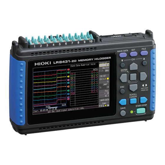
Hioki LR8431-20 Measurement Manual
Portable handheld memory hilogger, heat flow logger
Hide thumbs
Also See for LR8431-20:
- Manual (37 pages) ,
- Instruction manual (204 pages) ,
- Measurement manual (32 pages)

Related Manuals for Hioki LR8431-20


Summary of Contents for Hioki LR8431-20
- Page 1 Measurement Guide LR8431-20 MEMORY HiLOGGER LR8432-20 HEAT FLOW LOGGER Jan. 2016 Revised edition 3 LR8431B981-03 16-01H...
- Page 3 Procedure Procedure Describes the screen types and an overview of the Operation and Screen Types operating keys. (p.15) Describes procedures from measurement prepara- Measurement Procedure tion to analysis. (p.19) This section describes voltage measurement using an AC transducer to acquire voltage fluctuation data for one week, with the data automatically saved on a Monitoring Voltage Fluctua- CF card.
-
Page 4: Confirming Package Contents
Introduction Introduction Thank you for purchasing the HIOKI “Model LR8431-20 Memory HiLogger” or “LR8432-20 Heat Flow Logger.” This Measurement Guide consists of some basic application examples. Before using the instrument, be sure to read the Instruction Manual carefully. The product appearance and screen shots shown in this document are based on Model LR8431-20. - Page 5 Confirming Package Contents Contact your authorized Hioki distributor or reseller. About options: Model 9780 Battery Pack Model 9728 PC Card (512M) Model Z1005 AC Adapter Model 9729 PC Card (1G) Model 9641 Connection Cable Model 9830 PC Card (2G) (for pulse inputs) ...
-
Page 6: Safety Information
Safety Information Safety Information This instrument is designed to conform to IEC 61010 Safety Standards, and has been thoroughly tested for safety prior to shipment. However, using the instrument in a way not described in this manual may negate the provided safety features. Before using the instrument, be certain to carefully read the following safety notes: Mishandling during use could result in injury or death, as well... -
Page 7: Other Symbols
Safety Information Notation In this document, the risk seriousness and the hazard levels are classified as fol- lows. Indicates an imminently hazardous situation that will result in death or seri- ous injury to the operator. Indicates a potentially hazardous situation that may result in death or seri- ous injury to the operator. - Page 8 Safety Information Accuracy We define measurement tolerances in terms of f.s. (full scale), rdg. (reading) and dgt. (digit) values, with the following meanings: (maximum display value or scale length) f.s. The maximum displayable value or scale length. This is usually the name of the cur- rently selected range.
- Page 9 Safety Information Difference between “Measurement” and “Recording” The measurement and recording processes are distinguished as follows for the purposes of these instructions. The acquisition of input values into the instrument’s internal memory or to Measurement: a PC via communications. Storing measurement data on a CF card, USB flash drive or on a PC via Recording: data communication.
-
Page 10: Operating Precautions
• Before using the instrument, make sure that the insulation on the cables is undam- aged and that no bare conductors are improperly exposed. Using the instrument in such conditions could cause an electric shock, so your authorized Hioki distributor or reseller for replacements. - Page 11 Operating Precautions • Correct measurement may be impossible in the presence of strong magnetic fields, such as near transformers and high-current conduc- tors, or in the presence of strong electromagnetic fields such as near radio transmitters. • If liquid enters the enclosure through an air vent or other opening, it may damage the instrument’s internal circuitry.
-
Page 12: Handling The Instrument
Operating Precautions Handling the Instrument • Do not allow the instrument to get wet, and do not take mea- surements with wet hands. This may cause an electric shock. • Do not attempt to modify, disassemble or repair the instru- ment;... -
Page 13: Before Turning Power On
Operating Precautions Before Turning Power On Using the Battery Pack • For battery operation, use only the HIOKI Model 9780 Battery Pack. We do not take any responsibility for accidents or damage related to the use of any other batteries. - Page 14 Hioki distributor or reseller for inspection. IMPORTANT Select Hioki 9641 Connection Cable for use as a cable for the pulse input connector. The waveform for an open channel may sometimes appear to be influ- enced by the signals of the other channels being measured.
- Page 15 • Keep discs inside a protective case and do not expose to direct sun- light, high temperature, or high humidity. • Hioki is not liable for any issues your computer system experiences in the course of using this disc. Using a CF Card/USB flash drive •...
- Page 16 • Although real-time saving to USB flash drive is supported, a CF card is recommended for data preservation. Performance cannot be guaranteed when using storage media other than a Hioki-specified CF card option. • Use a USB flash drive whose continuous current consumption does not exceed 300 mA (peak 500 mA).
- Page 17 Operation and Screen Types Operation and Screen Types CF Card Slot Changing screen contents USB Port Analog Input Operating Keys Terminals Select the item to change. Show available setting options. (Rear) Select the desired Battery setting. POWER Compartment Switch Pulse Input Apply the new set- USB flash Connector...
- Page 18 Operation and Screen Types Waveform/Numerical Screens Selects between seven display types. The screen switch- [Gauge+Wave] Screen [Wave] Screen es each time you Measurement data is displayed Measurement data is displayed press the key. as waveforms with gauges. as waveforms. Operational infor- mation is displayed along the bottom of the screen.
-
Page 19: Settings Screens
Operation and Screen Types Settings Screens Selects between seven display types. The screen switch- es each time you Setting Screen CH Screen press the key. Make settings for recording. Make input channel settings numerical calculation, while viewing the monitor dis- auto-saving and timers. -
Page 20: File Screen
Operation and Screen Types File Screen Operational infor- mation is displayed along the bottom of the screen. File Screen View and manage files on the CF Card or USB flash drive. -
Page 21: Measurement Procedure
Connect the Heat Flow Sensor. * (LR8432-20 only) For pulse input signals: Pulse Input Connector connect the Hioki 9641 Connection Cable . Insert a CF Card or USB flash drive (option) Confirm that sufficient free space is available, and for auto-saving,... -
Page 22: Turn The Power On
Measurement Procedure Turn the power on Right Side View Connect to the measurement object Configure settings for measurement Configure recording settings on the Setting screen. • Recording interval • Recording length • Auto-saving (if used) Make other settings as necessary. Configure input channel set- tings on th e CH s creen. - Page 23 Measurement Procedure Start and finish measuring Press to start and stop recording with the selected measurement conditions. When [Repeat] [Off] (default setting), one recording length is acquired, and recording Stop Start stops automatically. Measurement Measurement When [Repeat] is [On], recording proceeds continuously.
- Page 24 * The example transducer provides 0 V to 10 V DC output proportional to 0 V to 150 V AC rms input. Prepare the Following Before Measuring Insert a CF card Items to prepare Connect to CH1 Model LR8431-20 Memory HiLogger or Model MR8432- 20 Heat Flow Logger AC Adapter (supplied) ...
- Page 25 Monitoring Voltage Fluctuations Make input channel settings on the CH screen. Select Apply Setting Example Channel: CH1, Input: Voltage, Range: 10V 10 V 150 V Make other settings as necessary. Disp Span: Position, 0 pos: 0% (displays zero volts at the bottom of the screen) Scaling: Dec, 2-pt Cnv 1: 0 V to 0 V , Cnv 2: 10 V to 150 V for display Start and Stop Measurement...
- Page 26 The procedure for saving measurement data to a CF card after measuring is also described. Prepare the Following Before Measuring Insert a CF card Items to prepare Connect to CH1 Model LR8431-20 Memory HiLogger or Model MR8432- 20 Heat Flow Logger AC Adapter (supplied) Thermocouples (K) ...
- Page 27 Monitoring Temperature Changes Make input channel settings on the CH screen. Select Apply The default settings for the non- Setting Example Channel: CH1, Input: Tc, K (Thermocouple) framed items can be left as-is. RJC: Int Change as needed. Set the open-circuit detection and display range as neces- sary.
- Page 28 Monitoring Temperature Changes Saving Data After Measuring This section describes how to save data after measuring. Two methods are available for saving measurement data to a CF card or USB flash drive after recording: [Select & Save] [Quick Save] Press the key and select to set the saving data type and make [Select &...
- Page 29 * The example watt-hour meter provides an output of 50,000 pulses/kWh. Prepare the Following Before Measuring Insert a CF card Items to prepare Connect the 9641 Model LR8431-20 Memory Connection cable HiLogger or Model MR8432- 20 Heat Flow Logger...
- Page 30 Monitoring Energy Consumption Make input channel settings on the CH screen. Select Apply Setting Example Channel: P1, Input: Count, Count Mode: Add Use the scaling function to display values in kWh units. Cond: Dec, Unit: kWh, 1 Pulse = 20u [kWh], (E/P/T/G/M/k/ (blank) /m/ 1 kWh=50000 Pulse (+/ ‑)
- Page 31 Items to prepare LR8432-20 Heat Flow Logger AC Adapter (supplied) Heat Flow Sensor* Type K thermocouple *. Hioki option Connect Connect to the to power measurement point outlet Turn the power on (Refer to the instruction (Right side) manual of the Heat Flow Sensor for the procedure to connect it.)
- Page 32 Monitoring Heat Flow (Model LR8432-20 only) Make input channel settings on the CH screen. CH1 Setting Select Apply Setting Example Channel: CH1, Input: Heat, Range: 10 mV Enter the sensitivity constant of the sensor. The test report that comes with the Heat Flow Sensor contains the sensor’s sensitivity constant.
- Page 33 Monitoring Heat Flow (Model LR8432-20 only) Start and Stop Measurement Press the key. START/STOP In this case, measurement data are re- corded until you press the START/ key again. STOP...
- Page 34 Monitoring Heat Flow (Model LR8432-20 only) Observe the Waveform, Displaying Two Gauges (As necessary) Observe the waveform, displaying two gauges on the [Gauge+Wave] screen of the waveform screen. It is effective to assess the correlation between the heat flow and the temperature.
- Page 35 Analysis Analysis Viewing a Measurement Waveform Scrolling the Waveform Earlier Later Currently Displayed Portion The portion of a waveform that is currently dis- Whole Waveform played can be confirmed by the position of the scroll bar. Zooming the Waveform View Zooming (Magnifying and Reducing) the Horizontal Axis Specify the time per divi-...
-
Page 36: View Measurement Values
Analysis View Measurement Values The values at the cursors are displayed. Press these keys to move the cursor on the displayed waveform. To change the cursor type, select from the [Type] setting items. • Trace (time value and measure- ment value) •... -
Page 37: Specifying A Range
Analysis Specifying a Range Movable Cursor Select either [Trace] [Vert] (vertical) cursor type. Specify the Range. To select which cursor(s) to move Select whether to move Cursor A, Cursor B, or both together. - Page 38 Analysis Calculate Measurement Data Up to four types of calculations can be applied at the same time. Calculation types: Average, peak value, maximum, minimum, time to maximum, time to minimum, and sum (LR8432 only) Press the key several times to display WAVE/DATA [Wave+Calc] The numerical calcula-...
- Page 39 Analysis View CF Card/USB Flash Drive Contents Data saved by the instrument can be confirmed on the File screen. It is stored on the CF Card or USB flash drive as follows. The numbers in the file names are automati- cally generated sequentially.
- Page 40 Analysis Analyzing HiLogger Data on a Computer Recorded data can be analyzed and HiLog- ger settings can be changed using a com- puter running the supplied application program. Not only waveforms, but also nu- merical values and alarm output states can be monitored in real time.
Need help?
Do you have a question about the LR8431-20 and is the answer not in the manual?
Questions and answers