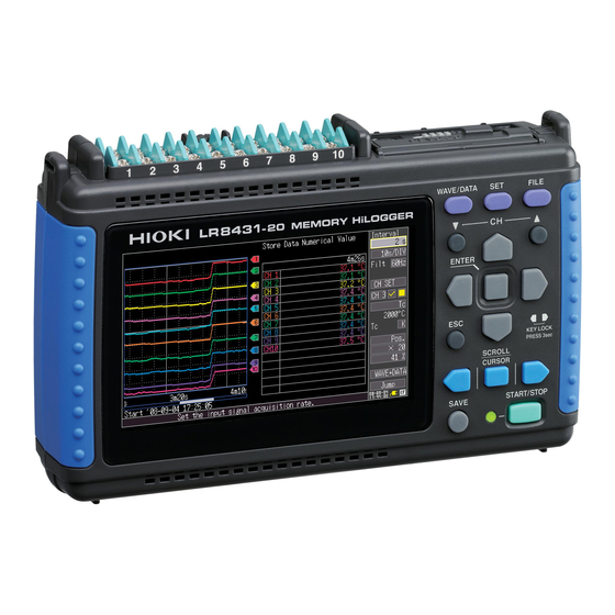
Hioki LR8431-20 Manual
Memory hilogger
Hide thumbs
Also See for LR8431-20:
- Instruction manual (204 pages) ,
- Measurement manual (44 pages) ,
- Measurement manual (32 pages)
Table of Contents
Advertisement
Quick Links
Download this manual
See also:
Instruction Manual
Advertisement
Table of Contents

Related Manuals for Hioki LR8431-20


Summary of Contents for Hioki LR8431-20
- Page 1 Measurement Guide LR8431-20 MEMORY HiLOGGER April 2013 Revised edition 2 LR8431B981-02 13-04H...
- Page 3 Procedure Procedure Operation and Screen Types Describes the screen types and an overview of the operating keys. (p.12) Measurement Procedure Describes procedures from measurement prepara- tion to analysis. (p.16) This section describes voltage measurement using an AC transducer* to acquire voltage fluctuation data Monitoring Voltage Fluctua- for one week, with the data automatically saved on a CF card.
-
Page 4: Confirming Package Contents
Introduction Introduction Thank you for purchasing the HIOKI "Model LR8431-20 Memory HiLogger." This Measurement Guide consists of some basic application examples. Before using the instrument, be sure to read the Instruction Manual carefully. Confirming Package Contents When you receive the instrument, inspect it carefully to ensure that no damage occurred during shipping. -
Page 5: Safety Information
Safety Information Safety Information This instrument is designed to comply with IEC 61010 Safety Standards, and has been thoroughly tested for safety prior to shipment. However, mishandling during use could result in injury or death, as well as damage to the instrument. However, using the instrument in a way not described in this manual may negate the provided safety features.... -
Page 6: Other Symbols
Safety Information Symbols for Various Standards This symbol indicates that the product conforms to safety regulations set out by the EC Directive. This is a recycle mark established under the Resource Recycling Promotion Law (only for Japan). Ni-MH WEEE marking: This symbol indicates that the electrical and electronic appliance is put on the EU market after August 13, 2005, and producers of the Member States are required to display it on the appliance under Article 11.2 of Directive 2002/96/... - Page 7 Safety Information Measurement categories To ensure safe operation of measurement instruments, IEC 61010 establishes safety stan- dards for various electrical environments, categorized as CAT II to CAT IV, and called mea- surement categories. Primary electrical circuits in equipment connected to an AC electrical outlet CAT II by a power cord (portable tools, household appliances, etc.) CAT II covers directly measuring electrical outlet receptacles.
-
Page 8: Operating Precautions
• Before using the instrument, make sure that the insulation on the cables is undam- aged and that no bare conductors are improperly exposed. Using the instrument in such conditions could cause an electric shock, so contact your dealer or Hioki rep- resentative for replacements. -
Page 9: Handling The Instrument
Operating Precautions • Correct measurement may be impossible in the presence of strong magnetic fields, such as near transformers and high-cur- rent conductors, or in the presence of strong electromagnetic fields such as near radio transmitters. • If liquid enters the enclosure through an air vent or other opening, it may damage the instrument's internal circuitry. -
Page 10: Before Turning Power On
Before Turning Power On Using the Battery Pack • For battery operation, use only the HIOKI Model 9780 Battery Pack. We do not take any responsibility for accidents or damage related to the use of any other batteries. - Page 11 When an abnormal measurement value is observed, please contact your dealer or Hioki representative for inspection. The waveform for an open channel may sometimes appear to be influenced by the signals of the other channels being measured.
- Page 12 Never use abrasives or solvent cleaners. • Hioki shall not be held liable for any problems with a computer system that arises from the use of this CD, or for any problem...
- Page 13 • Although real-time saving to USB flash drive is supported, a CF card is recommended for data preservation. Performance cannot be guaranteed when using storage media other than a Hioki-specified CF card option. • Use a USB flash drive whose continuous current consumption does not exceed 300 mA (peak 500 mA).
- Page 14 Operation and Screen Types Operation and Screen Types CF Card Slot Changing screen contents USB Port Analog Input Operating Keys Terminals Select the item to change. Show available setting options. (Rear) Select the desired Battery POWER setting. Compartment Switch Pulse Input ...
- Page 15 Operation and Screen Types Waveform/Numerical Screens Selects between seven display types. The screen switch- [Gauge+Wave] Screen [Wave] Screen es each time you Measurement data is displayed Measurement data is displayed press the key. as waveforms with gauges. as waveforms. Operational infor- mation is displayed along the bottom of the screen.
-
Page 16: Settings Screens
Operation and Screen Types Settings Screens Selects between seven display types. The screen switch- Setting Screen CH Screen es each time you press the key. Make settings for recording. Make input channel settings numerical calculation, while viewing the monitor dis- auto-saving and timers. -
Page 17: File Screen
Operation and Screen Types File Screen Operational infor- mation is displayed along the bottom of the screen. File Screen View and manage files on the CF Card or USB flash drive. -
Page 18: Measurement Procedure
Analog Input Top View Terminals For pulse input signals: connect the Hioki 9641 Connection Cable . Pulse Input Connector Insert a CF Card or USB flash drive (option) Confirm that sufficient free space is available, and for auto-saving,... -
Page 19: Turn The Power On
Measurement Procedure Turn the power on Right Side View Connect to the measurement object Configure settings for measurement Configure recording settings on the Setting screen. • Recording interval • Recording length • Auto-saving (if used) Make other settings as necessary. Configure input channel set- tings on th e CH s creen. - Page 20 Measurement Procedure Start and finish measuring Press to start and stop recording with the selected measurement conditions. When [Repeat] [Off] (default setting), one recording length is acquired, and recording Stop Start stops automatically. Measurement Measurement When [Repeat] is [On], recording proceeds continuously.
- Page 21 * The example transducer provides 0 - 10 V DC output proportional to 0 - 150 Vrms AC input. Prepare the Following Before Measuring Insert a CF card Items to prepare Connect to CH1 Model LR8431-20 Memory HiLogger AC Adapter (supplied) Measu rement (input) leads ...
- Page 22 Monitoring Voltage Fluctuations Make input channel settings on the CH screen. Select Apply Setting Example Channel: CH1, Input: Voltage, Range: 10V 10 V 150 V Make other settings as necessary. Disp Span: Position, 0 pos: 0% (displays zero volts at the bottom of the screen) Scaling: Dec, 2-pt Cnv 1: 0 V to 0 V , Cnv 2: 10 V to 150 V for display Start and Stop Measurement...
- Page 23 The procedure for saving measurement data to a CF card after measuring is also described. Prepare the Following Before Measuring Insert a CF card Items to prepare Connect to CH1 Model LR8431-20 Memory HiLogger AC Adapter (supplied) ThermoCouples (K) ...
- Page 24 Monitoring Temperature Changes Make input channel settings on the CH screen. Select Apply Setting Example The default settings for the non- Channel: CH1, Input: Tc, K (Thermocouple) framed items can be left as-is. RJC: Int Change as needed. Set the open-circuit detection and display range as neces- sary.
- Page 25 Monitoring Temperature Changes Saving Data After Measuring This section describes how to save data after measuring. Two methods are available for saving measurement data to a CF card or USB flash drive after recording: [Select & Save] [Quick Save] Press the SAVE key and select to set the saving data type and make...
- Page 26 * The example watt-hour meter provides an output of 50,000 pulses/kWh. Prepare the Following Before Measuring Insert a CF card Items to prepare Connect the 9641 Model LR8431-20 Memory Connection cable HiLogger Connect to the AC Adapter (supplied) ...
- Page 27 Monitoring Energy Consumption Make input channel settings on the CH screen. Select Apply Setting Example Channel: P1, Input: Count, Count Mode: Add Use the scaling function to display values in kWh units. Cond: Dec, Unit: kWh, 1 Pulse = 20u [kWh], (E/P/T/G/M/k/ (blank) /m/ 1 kWh=50000 Pulse (+/ -)
- Page 28 Analysis Analysis Viewing a Measurement Waveform Scrolling the Waveform Earlier Later Currently Displayed Portion The portion of a waveform that is currently dis- Whole Waveform played can be confirmed by the position of the scroll bar. Zooming the Waveform View Zooming (Magnifying and Reducing) the Horizontal Axis Specify the time per divi-...
-
Page 29: View Measurement Values
Analysis View Measurement Values The values at the cursors are displayed. Press these keys to move the cursor on the displayed waveform. To change the cursor type, select from the [Type] setting items. • Trace (time value and measure- ment value) •... -
Page 30: Specifying A Range
Analysis Specifying a Range Movable Cursor Select either [Trace] [Vert] (vertical) cursor type. Specify the Range. To select which cursor(s) to move Select whether to move Cursor A, Cursor B, or both together. - Page 31 Analysis Calculate Measurement Data Up to four types of calculations can be applied at the same time. Calculation types: Average, peak value, maximum, minimum, time to maximum and time to minimum Press the WAVE/DATA key several times to display [Wave+Calc] The numerical calcula- tion window appears.
- Page 32 Analysis View CF Card/USB flash drive Contents Data saved by the LR8431-20 can be confirmed on the File screen. It is stored on the CF Card or USB flash drive as follows. The numbers in the file names are auto- matically generated sequentially.
- Page 33 Analysis MEMO...
- Page 34 Analysis MEMO...
Need help?
Do you have a question about the LR8431-20 and is the answer not in the manual?
Questions and answers