Table of Contents
Advertisement
Quick Links
Advertisement
Table of Contents

Subscribe to Our Youtube Channel
Related Manuals for Hioki LR8410-20


Summary of Contents for Hioki LR8410-20
-
Page 3: Table Of Contents
Contents Contents Introduction ................1 Confirming Package Contents ..........2 Safety Information..............4 Operating Precautions.............7 Chapter 1 Overview ____________________________________21 Product Overview and Features ......21 Measurement Flow ..........22 Names and Functions of Parts, Screen Configurations ............26 Wireless Logging Station ..........26 UNIT .................29 ... - Page 4 Contents Connecting the AC Adapter ........44 Making Connections ..........46 Pre-Connection Inspection ..........46 Voltage and Thermocouple Temperature Measurement . 47 Temperature Measurement with a Resistance Temperature Detector (RTD) ..... 49 Humidity Measurement ............ 50 ...
- Page 5 Contents Resistance Measurement Settings ........81 Integration (Count) Measurement Settings ......82 Revolution Measurement Settings ........84 Logic Measurement Settings ..........86 Current Measurement Settings ........87 Fungal Index and Fungal Growth Projection Settings ..89 Alarm Settings ............90 Data Saving Settings ..........90 Waveform Display Settings (as needed) ....91 ...
- Page 6 Contents Observing Waveforms .......... 113 Displaying Waveforms (Display Descriptions) ....113 Displaying Gauges ............114 Viewing Input Signals as Numerical Values ....115 Scrolling Waveforms ............116 Verifying Waveform Display Position ......116 Magnifying and Compressing Horizontally ..... 117 ...
- Page 7 Contents Starting & Stopping Measurement Periodically .............143 Canceling a Schedule ...........145 About Schedule Function Operation ....147 Setting Examples ...........150 Alarm Output ............151 Checking Alarm Criteria ..........152 Alarm Settings ..............155 Chapter 6 Saving & Loading Data ___________________ 159 About Saving and Loading Data ......159 ...
- Page 8 Contents Chapter 7 Numerical Calculations/ Waveform Calculations____________________ 183 Calculate Average, Maximum, Minimum, and Etc..............183 Key Setting Procedure ........... 186 Real-Time Calculation While Measuring (Auto Calculation) ............186 Calculation after Measuring (Manual Calculation) ..188 ...
- Page 9 Contents Making System Settings ........202 Setting the Date and Time ..........202 Initializing the instrument (System Reset) ......203 Self-Test .................204 Chapter 9 External Control __________________________ 205 External Trigger Input ...........205 External Signal Output (Trigger Output) .....206 Alarm Signal Output (Alarm Output) ....207 Synchronous Measurements with ...
- Page 10 Measurement value errors ..........274 Measurement values ............274 Chapter 12 Specifications _____________________________ 275 12.1 LR8410-20 Wireless Logging Station Specifications ............275 12.2 LR8510 Wireless Voltage/Temp Unit Specifications ............286 12.3 LR8511 Wireless Universal Unit Specifications . 292...
- Page 11 Contents Chapter 13 Maintenance and Service_________________ 299 13.1 Inspection, Repair, and Cleaning ......299 13.2 Troubleshooting ............301 13.3 Disposing of the instrument .........303 Removing the Lithium Battery ........303 Appendix ___________________________________ A1 Appendix 1 Scan Timing ............. A1 Appendix 2 Error Messages and Remedial Actions ..A3 Appendix 3 File Naming ............
- Page 12 Contents...
-
Page 13: Contents
Introduction Introduction Thank you for purchasing the HIOKI Model LR8410-20 Wireless Logging Station.To obtain maximum performance from the instrument and measurement units, please read this manual first, and keep it handy for future reference. This document uses the following device names:... -
Page 14: Confirming Package Contents
In particular, check the accessories, panel switches, and connectors. If damage is evident, or if it fails to operate according to the specifica- tions, contact your authorized Hioki distributor or reseller. Confirm that these contents are provided. - Page 15 Confirming Package Contents Options Contact your authorized Hioki distributor or reseller for details. LR8510 Wireless Voltage/Temp Unit Z1007 Battery Pack LR8511 Wireless Universal Unit Z1008 AC Adapter LR8512 Wireless Pulse Logger C1007 Carrying Case ...
-
Page 16: Safety Information
Safety Information Safety Information This instrument and measurement units are designed to comply with IEC 61010 Safety Standards, and has been thoroughly tested for safety prior to shipment. However, mishan- dling during use could result in injury or death, as well as damage to the instrument and measurement units. - Page 17 Safety Information Symbols for Various Standards Indicates that the product conforms to regulations set out by the EU Directive. Indicates the ID number of the wireless module certified by the U.S. Federal Com- FCC ID munications Commission (FCC). Indicates the number of the wireless module certified by Industry Canada. This is a recycle mark established under the Resource Recycling Promotion Law (only for Japan).
- Page 18 • Never use a measuring HiLogger that lacks category labeling in a CAT II to CAT IV measurement environment. Doing so could result in a serious accident. Hioki LR8510 Wireless Voltage/Temp Unit and LR8511 Wireless Universal Unit complies with CAT II (300 VAC, DC) safety requirements. CAT II:...
-
Page 19: Operating Precautions
Wireless Universal Unit and the Wireless Logging Station are encrypted using SSP, this does not guarantee the integrity or secrecy of transmitted data. Hioki is not liable for the electronic interception or unauthorized dis- closure by other means of measured values sent via wireless communi- cations. - Page 20 • Before using the instrument, make sure that the insulation on the cables is undamaged and that no bare conductors are improperly exposed. Using the instrument in such conditions could cause an electric shock, so contact your authorized Hioki distributor or reseller for replacements.
- Page 21 Operating Precautions Handling the Instrument To avoid electric shock, do not remove the instrument's case. The internal components of the instrument carry high voltages and may become very hot during operation. Touching any of the high-voltage points inside the instrument is very dangerous.
- Page 22 • Use the Z1007 Battery Pack with the instrument and measurement units. Use of other battery packs may damage the device or cause an accident. Hioki is not liable for such damage. "2.1 Using the Battery Pack (Option)" (p. 41) See: •...
- Page 23 • Using this battery pack in devices other than those designated by Hioki may degrade its performance or service life, and some devices may trigger an abnormal current flow or damage the bat- tery pack, causing it to leak, become excessively hot, generate smoke, crack, or catch on fire.
- Page 24 • Transport of lithium-ion batteries on aircraft is subject to restrictions based on UN recom- mendations. • Before repairing or calibrating devices that use the Z1007 Battery Pack or transporting them on an aircraft, contact your authorized Hioki distributor or reseller.
- Page 25 Operating Precautions Using the AC Adapter • Use only the supplied Model Z1008 AC Adapter. AC adapter input voltage range is 100 to 240 VAC (with ±10% stability) at 50/60 Hz. To avoid electrical hazards and damage to the instrument and mea- surement units, do not apply voltage outside of this range.
- Page 26 Operating Precautions Handling of temperature and humidity sensor Model Z2000 Humidity Sensor and Model Z2010/Z2011 Humidity Sensor are not dustproof or waterproof. Do not use the sensor in locations where it may be exposed to dust or water. It may cause a malfunction of the instrument.
- Page 27 Operating Precautions Connection Precautions When connecting measurement cables to a Wireless Voltage/Temp Unit or Wireless Universal Unit Do not leave the Unit connected to test objects in environments where a voltage surge might exceed the dielectric withstand voltage. Doing so could result in damage to the measurement units, bodily injury or fatal accident.
- Page 28 Please ensure that a voltage beyond specification, especially a surge such as a lightning, is never applied. When an abnormal measurement value is observed, please contact your authorized Hioki distributor or reseller for inspection. Input and Output Maximum Maximum rated Max.
- Page 29 Operating Precautions When connecting to the instrument’s alarm output terminals or external con- trol terminal • To avoid electric shock or damage to the instrument, always observe the following precautions when connecting to alarm output terminals and External Control Terminals. •...
- Page 30 Operating Precautions Using a SD memory card/USB flash drive • Store SD memory cards and USB flash drives out of reach of chil- dren to prevent accidental ingestion. • Do not modify, disassemble, or repair SD memory cards or USB flash drives.
- Page 31 • Keep discs inside a protective case and do not expose to direct sunlight, high temperature, or high humidity. • Hioki is not liable for any issues your computer system experiences in the course of using this disc.
- Page 32 Operating Precautions...
-
Page 33: Chapter 1 Overview
Chapter 1 Overview 1.1 Product Overview and Features The LR8410-20 Wireless Logging Station allows the collection and observation of data transmitted wirelessly from measurement unit and wireless logger that have been placed in remote measurement locations. Voltage change, temperature, humidity, and resis-... -
Page 34: Measurement Flow
1.2 Measurement Flow 1.2 Measurement Flow 1. Register measurement units, and wireless loggers with the instrument Each instrument can connect wirelessly to up to seven measurement units, and wireless loggers. Once a measurement unit and wireless logger has been registered, device registration information will be saved even if the instrument, measurement units, and wireless log- gers are turned off (p. - Page 35 1.2 Measurement Flow 2. Prepare for measurement (installation and wiring). (1) Insert the SD memory card (included) into the instrument. (2) Attach the fixed stand (optional feature) and mounting bracket (included) Instrument :Use the Z1009 Fixed Stand to place the instrument at an angle on a table or desk or mount it on a wall.
- Page 36 1.2 Measurement Flow (3) Connect the measurement (4) Connect the measurement unit and wire- cables.(p. 46) less logger to the measurement target. 3. Set the measurement conditions.(p. 68) Configure Recording Settings (p. 68) Set the data acquisition (record- ing) interval ([Interval]), and re- cording length ([Record time]).
- Page 37 1.2 Measurement Flow 4. Correct for input unit divergence. (Zero Adjustment)(p. 63) 5. Starting and Stopping Measurement (p. 36) Press the START STOP Measure (Record) once, and stop. Start Measurement (default setting) [Repeat]: Off Stop Measure- Measure (Record) repeatedly. ment [Repeat]: On When measuring (recording) using the trigger function (p.
-
Page 38: Names And Functions Of Parts, Screen Configurations
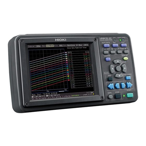
1.3 Names and Functions of Parts, Screen Configurations 1.3 Names and Functions of Parts, Screen Configurations Wireless Logging Station Front Panel External Control Terminals (p. 28) Display Screen (p. 113) 5.7-inch TFT color LCD Screen Configurations (p. 34) Operating Keys/LED (p. 27) Rear Panel MAC address Battery Compartment (p. - Page 39 1.3 Names and Functions of Parts, Screen Configurations Operating Keys/LED Instrument status POWER ■Warning(Alarm) Lights when powered on (p. 54). CHARGE Lights up when any of the four alarm channels satisfies the alarm conditions. Lights while charging the Z1007 Battery Pack (p.
- Page 40 1.3 Names and Functions of Parts, Screen Configurations Upper Side LAN cable port Use for PC communications via LAN. Connect an optional Model 9642 LAN Cable (p. 231). USB Cable Port SD memory card Slot (USB 2.0 mini-B receptacle) POWER Switch Use to save data to a SD memory card.
-
Page 41: Unit
1.3 Names and Functions of Parts, Screen Configurations UNIT Front Panel Unit No. The LED for the registered unit number will light up. If the communications status is poor, the LED will flash. • AC ADAPTER Lights up when power is being sup- plied from the AC adapter or another external source. -
Page 42: Measurement Units
Z2000 Humidity Sensor.(p. 46) Measurement Parameter • Voltage • Temperature (thermocouple or resistance temperature detec- tor) • Resistance • Humidity (using Hioki Z2000 Humidity Sensor) CH15 Push-button terminal block Input channels: 15... -
Page 43: Wireless Logger
1.3 Names and Functions of Parts, Screen Configurations Wireless logger For more information about part names and functionality, see the wireless logger's User Manual. Types of wireless logger The wireless logger is available in the five types shown below. For more information about wireless logger specifications, see each model's User Manual. -
Page 44: Lr8514 Wireless Humidity Logger
1.3 Names and Functions of Parts, Screen Configurations LR8514 Wireless Humidity Logger The LR8514 provides temperature and humidity measurement. Measurement Parameter • Temperature • Humidity Connection terminal External temperature/humidity sensor: Z2010/Z2011 Humidity Sensor No. of input channels: 2 (2 temperature channels + 2 humidity channels) LR8515 Wireless Voltage/Temp Logger The LR8515 provides voltage measurement and thermocouple-based temperature mea-... - Page 45 1.3 Names and Functions of Parts, Screen Configurations About the Icons (on all screens) (Bottom of the screen) SD memory card, Clock USB flash drive "Setting the Date and Time" (p. 202) Displayed when a SD memory card/ Power source indicator USB flash drive is inserted.
- Page 46 1.3 Names and Functions of Parts, Screen Configurations Settings Screens [Setting] Screen [CH] Screen [UNIT] Screen Make settings for recording Make input channel settings while Register measurement units and viewing the monitor display (p. 68).Set numerical calculation, wireless loggers. auto-saving and reservation.
-
Page 47: Basic Operation
1.4 Basic Operation 1.4 Basic Operation Screen Operations (changing settings, scrolling waveforms, and displaying values) Changing screen contents Select the item to change. Show available setting options. Setting Screen Select the desired setting. Apply the new set- ting, or cancel it. Waveform/Numerical Screen Scrolling a waveform Hide A/B cursors... -
Page 48: Starting And Stopping Measurement
1.4 Basic Operation Starting and Stopping Measurement Start measuring (acquiring measurement data) as follows. When Auto saving is enabled, data is recorded to the specified removable storage (SD memory card or USB flash drive) as it is being recorded to internal buffer memory. Start Measurement Press START. - Page 49 1.4 Basic Operation About Measuring Operation About Continuous and Repeating Recording: (p. 68) See: Press START Press STOP Record time Repeat: Off Repeat: On Recording Recording time time Measuring Measuring Time Start Start Stop Stop Measuring Measuring Measuring Dead time Measuring Recording Recording time...
-
Page 50: Disabling Key Operations (Key-Lock Function)
1.4 Basic Operation Disabling Key Operations (Key-Lock Function) Keys can be disabled to avoid inadvertent operations. Press and hold the key for three seconds to lock the other keys, and repeat to unlock. Performing Zero Adjustment [CH] With the Waveform/Numerical or screen displayed, press the up and down cursor keys simultaneously. -
Page 51: Saving Data
1.4 Basic Operation Saving Data Measurement data, settings, screen images and numerical calculation results can be saved. For details of the saving methods, see "Chapter 6 Saving & Loading Data" (p. 159). (Default settings) Saving Method: [Select & Save] (Press to select and save data.) SAVE Select the save destination... -
Page 52: Confirming Inputs (Monitor)
1.4 Basic Operation Confirming Inputs (Monitor) You can confirm the status of inputs and display ranges with the current settings (data is not acquired to internal buffer memory). This function is convenient for checking measured values before activating real-time sav- ing(Auto saving). -
Page 53: Measurement Preparations
Charge the battery pack fully before using it the first time. Be sure to read "Using the Battery Pack" (p .10) before installing. Install the Battery Pack Required items: phillips screwdriver (No.2), Hioki Z1007 Battery Pack Instrument Measurement units Turn off the instrument. -
Page 54: Charge The Battery Pack
2.1 Using the Battery Pack (Option) Charge the Battery Pack An attached battery pack can be charged whenever the instrument or measurement unit is connected to commercial power using the Z1008 AC Adapter, regardless of whether the instrument or unit is turned on. (p. 44) Instrument The CHARGE LED lights orange when... - Page 55 2.1 Using the Battery Pack (Option) When to charge Instrument: When powering the instrument from the battery pack without the Model Z1008 AC Adapter, the low battery indicator ( ) is displayed when the battery is almost out of power, indicating that the battery pack requires charging. The battery will be completely out of power approximately 10 minutes after the instru- ment’s battery icon changes to ( ) (after being fully charged, with 2 measurement...
-
Page 56: Connecting The Ac Adapter
2.2 Connecting the AC Adapter 2.2 Connecting the AC Adapter Connect the included Z1008 AC Adapter and power cord to the instrument and measurement units and plug the cord into a wall outlet. When used with the battery pack installed, the battery serves as an operating backup supply in case of power failure, and the AC adapter otherwise has priority. - Page 57 2.2 Connecting the AC Adapter Connect the output plug Rated supply voltage is 100 to 240 VAC, of the AC adapter to the and rated supply frequency is 50 or 60 Hz. instrument. Insert the cord into the (Instrument) groove on the corner of Connect the the instrument to keep it power cord...
-
Page 58: Making Connections
Before using the instrument and measurement units the first time, verify that it operates normally to ensure that no damage occurred during storage or shipping. If you find any damage, contact your authorized Hioki distributor or reseller. Peripheral Equipment Inspection Metal Exposed Do not use if damage is... -
Page 59: Voltage And Thermocouple Temperature Measurement
2.3 Making Connections If connecting crimped terminals to the analog input terminals, use insulated terminals for M3 screws with the size shown below. 6 mm 6 mm max. max. Voltage and Thermocouple Temperature Measurement <Connecting to the terminals of the Wireless Voltage/Temp Unit> Required items: phillips screwdriver (No.2), measurement leads (for voltage measure- ment), or thermocouple (for temperature measurement) Loosen the screws in the termi-... - Page 60 2.3 Making Connections <Connecting to the terminals of the Wireless Universal Unit> Required items: phillips screwdriver (No.2), flat-blade screwdriver (tip width 2.6 mm), measurement leads (for voltage measurement), or thermocouple (for temperature measurement) Recommended wire diameter: Single strand diameter:0.4 mm - 1.2 mm (AWG26-16) Multi-strand:0.2 mm - 0.75 mm (AWG24-20)...
-
Page 61: Temperature Measurement With A Resistance Temperature Detector (Rtd)
2.3 Making Connections Temperature Measurement with a Resistance Temperature Detector (RTD) <Connecting to the terminals of the Wireless Universal Unit> Required items: phillips screwdriver (No.2), flat-blade screwdriver (tip width 2.6 mm), Recommended wire diameter: Single strand diameter:0.4 mm - 1.2 mm (AWG26-16) Multi-strand:0.2 mm - 0.75 mm (AWG24-20)... -
Page 62: Humidity Measurement
Humidity Measurement <Connecting to the terminals of the Wireless Universal Unit> Required items: phillips screwdriver (No.2), flat-blade screwdriver (tip width 2.6 mm), Hioki Z2000 Humidity Sensor With a Phillips screwdriver, With the button held in, insert loosen the screws in the terminal... -
Page 63: Resistance Measurement
2.3 Making Connections Resistance Measurement <Connecting to the terminals of the Wireless Universal Unit> Required items: phillips screwdriver (No.2), flat-blade screwdriver (tip width 2.6 mm), measurement leads Recommended wire diameter: Single strand diameter:0.4 mm - 1.2 mm (AWG26-16) Multi-strand:0.2 mm - 0.75 mm (AWG24-20)... -
Page 64: Connecting Alarm Outputs
2.3 Making Connections Connecting Alarm Outputs < Connecting to the external control terminals > "9.3 Alarm Signal Output (Alarm Output)" (p. 207) See: Required items: flat-blade screwdriver (tip width 2.6 mm) (to connect wires to the push- button type terminal block on the top of the instrument), measurement leads Recommended wire diameter:... -
Page 65: External Control (Using Trig Out And Ext Trig)
2.3 Making Connections External Control (using TRIG OUT and EXT TRIG) < Connecting to the external control terminals > "9.1 External Trigger Input" (p. 205) See: "9.2 External Signal Output (Trigger Output)" (p. 206) See: Required items: flat-blade screwdriver (tip width 2.6 mm) (to connect wires to the push- button type terminal block on the top of the instrument), measurement leads Recommended wire diameter:... -
Page 66: Turning The Power On And Off
2.4 Turning the Power On and Off 2.4 Turning the Power On and Off Be sure to read "Before Turning Power On" (p .9) before turning power Turning Power On Verify that the instrument and peripheral (Wireless Logging Station) devices are correctly connected. Turn the power switch on. -
Page 67: Register Measurement Units And Wireless Logger With The Instrument
2.5 Register measurement units and wireless logger with the instrument 2.5 Register measurement units and wireless logger with the instrument • Settings can also be accessed from [QUICK SET] [Unit Guide]. • If there are no registered measurement units when the instrument starts up, the screen will default to [QUICK SET] [Unit... -
Page 68: Registering Measurement Units And Wireless Logger
2.5 Register measurement units and wireless logger with the instrument Registering Measurement Units and Wireless Logger Select the [UNIT] screen. Select [Add unit]. A search dialog box will be displayed. screen [Add unit] will be displayed. Select the unit you wish to temporarily register (up to sev- en may be selected). - Page 69 2.5 Register measurement units and wireless logger with the instrument To cancel the temporary registration Select [Delete]. Apply To search for measurement units again, select [Research]. When you do so, temporary registrations will be canceled, reverting the instrument to its state before the [Add unit] screen was opened.
-
Page 70: Deleting Registered Units
2.5 Register measurement units and wireless logger with the instrument Deleting Registered Units There are two ways to delete registered units. Deleting a registered unit from the [Delete unit] screen Select the [UNIT] screen. Select [Delete unit]. [Delete unit] screen will be displayed. - Page 71 2.5 Register measurement units and wireless logger with the instrument Deleting a registered unit from the [Add unit] screen Select the [UNIT] screen. Select [Add unit]. A search dialog box will be displayed. screen will be [Add unit] displayed.
-
Page 72: Inserting A Sd Memory Card Or Usb Flash Drive (When Saving Data)
2.6 Inserting a SD Memory Card or USB Flash Drive (when saving data) 2.6 Inserting a SD Memory Card or USB Flash Drive (when saving data) To save and reload the instrument measurement data, use the included or an optional SD memory card (as described below) or an after-market USB flash drive. Be sure to read "Using a SD memory card/USB flash drive"... -
Page 73: Sd Card Insertion & Removal
2.6 Inserting a SD Memory Card or USB Flash Drive (when saving data) SD Card Insertion & Removal Inserting a SD memory card cover Open the SD memory card slot cover. Face the SD memory card with the arrow mark on top ( ), and insert it in the direc- ... -
Page 74: Formatting A Sd Memory Card/Usb Flash Drive
2.6 Inserting a SD Memory Card or USB Flash Drive (when saving data) Formatting a SD memory card/USB flash drive The SD memory card or USB flash drive can be formatted by a PC or by the instrument. Format a new SD memory card or USB flash drive before use. This procedure describes how to format a SD memory card or USB flash drive in the instrument. -
Page 75: Compensating For Input Circuit Offset (Zero Adjustment)
2.7 Compensating for Input Circuit Offset (Zero Adjustment) 2.7 Compensating for Input Circuit Offset (Zero Adjustment) This step is only performed when using the LR8510 or LR8511. Zero adjustment corrects for voltage offset at the input terminals, so that the instru- ment measurements are relative to zero volts. - Page 76 2.7 Compensating for Input Circuit Offset (Zero Adjustment) • Any zero-adjust setting is cleared upon system reset (p. 203). (Zero-adjust values are only cleared for units that are connected. The unit’s zero-adjust values are not cleared when unit registration infor- mation is initialized.) •...
- Page 77 2.7 Compensating for Input Circuit Offset (Zero Adjustment) From the [List] screen [List] Display the screen [0 Adjust] Select Apply Zero adjustment is executed.
- Page 78 2.7 Compensating for Input Circuit Offset (Zero Adjustment)
-
Page 79: Chapter 3 Settings
3.1 Setting Flow Overview Chapter 3 Settings 3.1 Setting Flow Overview Configure measurement settings before starting to measure. Select the display method and configure auto saving as needed. After a measurement setting configuration has been saved (p. 170), you can start measuring immediately after loading the setting configuration data. -
Page 80: Configuring Measurement Settings
3.2 Configuring Measurement Settings 3.2 Configuring Measurement Settings Configure measurement settings on the [Setting] screen. The instrument provides continuous recording and timed recording. You can spec- ify whether to perform repeat recording for each. The Setting screen cannot be displayed while measuring. Start Measurement Stop Measurement Continuous... - Page 81 3.2 Configuring Measurement Settings Recording Interval (Interval) Select the data acquisition interval. Setting options:( : default setting) 100 ms , 200 ms, 500 ms, 1 s, 2 s, 5 s, 10 s, 20 s, 30 s, 1 min, 2 min, 5 min, 10 min, 20 min, 30 min, 1 h Repeat Recording (Repeat) Select whether to automatically start a new measurement after stopping, or to finish after...
- Page 82 3.2 Configuring Measurement Settings About the Recording Interval • Select the data acquisition interval to suit your measurement objectives. • Note that shorter recording intervals restrict the maximum recording time. • You can specify values starting at 100 ms without regard to the number of units.
- Page 83 3.2 Configuring Measurement Settings Data update interval Data is updated at the unit's minimum recording interval, regardless of the instrument's recording interval setting. Minimum recording interval Unit (data refresh interval) LR8510 100 ms LR8511 100 ms LR8512 100 ms LR8513 500 ms LR8514 500 ms...
-
Page 84: Input Channel Settings
3.3 Input Channel Settings 3.3 Input Channel Settings Configure the input channel settings on the [CH] screen. The Setting screen cannot be displayed while measuring. Input channels are as follows. Each channel can provide the following measurements. • Wireless Voltage/Temp Unit (UNIT1 to UNIT7, each with channels CH1 to CH15) •... -
Page 85: Key Setting Procedure
3.3 Input Channel Settings Key Setting Procedure Select the [CH] screen. Move to a setting item. Open the setting options for the item to be set. Select from the listed options. UNIT selects the input unit and CHAN select Apply the channel to be set. - Page 86 3.3 Input Channel Settings Monitor display switching Allows you to switch the information dis- played by the level monitor. (Settings on left) [Wave] Displays the waveform. [Value] Displays values for the units set on the right side of the screen. (Settings on right) Allows you to select which waveform to display if the setting on the left includes...
-
Page 87: Voltage Measurement Settings
3.3 Input Channel Settings Voltage Measurement Settings Configure these settings for each voltage measurement channel. "Key Setting Procedure" (p .73) See: Select the input unit (UNIT1 to 7) and channel (1-1 to 7-15), and check the box to enable the channel. Select [Voltage]. -
Page 88: Temperature Measurement Settings (Using Thermocouples)
3.3 Input Channel Settings Temperature Measurement Settings (using thermocouples) Follow this procedure to configure thermocouple temperature measurement channels. Make these settings on the [CH] screen. "Key Setting Procedure" (p .73) See: to 7) and channel Select the input unit (UNIT1 (1-1 to 7-15), and check the box to enable the channel. - Page 89 3.3 Input Channel Settings About Burn Out Detection • When burn out detection is enabled, the instrument detects wiring breaks by outputting a minus- cule current every recording interval during thermocouple measurement.? • Since the detection process uses different timing than measurement, this operation does not affect measured values.
-
Page 90: Temperature Measurement Settings (For Rtds)
3.3 Input Channel Settings Temperature Measurement Settings (for RTDs) Follow this procedure to configure resistance temperature detector (RTD) measurement channels. Make these settings on the [CH] screen. "Key Setting Procedure" (p .73) See: Select the input unit (UNIT1 and channel (1-1 to 7-15), and check the box to enable the channel. -
Page 91: Temperature Measurement Settings (When Lr8514 Or Lr8520 Is Used)
3.3 Input Channel Settings Temperature Measurement Settings (When LR8514 or LR8520 is used) Enable this channel setting for temperature measurement with the LR8514 Wireless Humidity Logger, R8520 Wireless Fungal Logger. Make these settings on the [CH] screen. "Key Setting Procedure" (p .73) See: Select the input unit (UNIT1... -
Page 92: Humidity Measurement Settings (When Lr8511 Is Used)
3.3 Input Channel Settings Humidity Measurement Settings (When LR8511 is used) Enable this channel setting for humidity measurement with the optional Z2000 Humidity Sensor. Make these settings on the [CH] screen. "Key Setting Procedure" (p .73) See: Select the input unit (UNIT1 to 7) and channel to 7), and check the box to enable the chan-... -
Page 93: Resistance Measurement Settings
3.3 Input Channel Settings Resistance Measurement Settings Make these channel settings for resistance measurement. Make these settings on the [CH] screen. "Key Setting Procedure" (p .73) See: Select the input unit (UNIT1 to 7) and channel (1-1 to 7-15), and check the box to enable the channel. -
Page 94: Integration (Count) Measurement Settings
3.3 Input Channel Settings Integration (Count) Measurement Settings Configure these settings for each pulse channel receiving input from a pulse output device such as a watt-hour or flow meter. Make these settings on the [CH] screen. "Key Setting Procedure" (p .73) See: Select the input unit (UNIT1... - Page 95 3.3 Input Channel Settings • Use the scaling function to display integrated pulse counts as the cor- responding physical units (such as Wh or VA) of the measurement parameter (p. 95). • The counter saturates at 1,073,741,823 counts. If you expect to exceed this count, we recommend measuring with the Integration Mode (Count Mo) set to Instantaneous (Inst), and summing later with a spreadsheet program.
-
Page 96: Revolution Measurement Settings
3.3 Input Channel Settings Revolution Measurement Settings Configure these settings for each pulse channel on which you will be counting pulses corresponding to revolutions, such as output from a rotary encoder or tachometer. The revolution measurement is obtained by counting the number of pulses input per second. Make these settings on the [CH] screen. - Page 97 3.3 Input Channel Settings Revolution Measurement Theory Pulse count is measured using the Memory HiLogger's internal 100 ms sampling interval. 0 100 ms 200 ms Pulse Count The revolution rate (r) per second during time t [s] is obtained by dividing the number of pulses from (t-1) to t [s] by the number of pulses per revolution.
-
Page 98: Logic Measurement Settings
3.3 Input Channel Settings Logic Measurement Settings Make these channel settings for logic measurements. Make these settings on the [CH] screen. "Key Setting Procedure" (p .73) See: : On : Off Select the input unit (UNIT1 to 7) and channel, and check the box to enable the channel. -
Page 99: Current Measurement Settings
3.3 Input Channel Settings Current Measurement Settings Make these channel settings for current measurements. Make these settings on the [CH] screen. "Key Setting Procedure" (p .73) See: : On : Off Select the input unit (UNIT1 to 7) and channel, and check the box to enable the channel. - Page 100 3.3 Input Channel Settings Select the zero-suppression setting. Setting options:( : default setting) Suppresses values of less than 10 counts in each range. Enables display of values of less than 10 counts. (For zero-adjustment purposes dur- ing DC measurement) Select the clamp measurement method.
-
Page 101: Fungal Index And Fungal Growth Projection Settings
3.3 Input Channel Settings Fungal Index and Fungal Growth Projection Settings Make these settings for fungal index and fungal growth projection channels. Make these settings on the [CH] screen. "Key Setting Procedure" (p .73) See: : ON : OFF Select the input unit (UNIT1 to 7) and chan- (1-1F... -
Page 102: Alarm Settings
3.4 Alarm Settings 3.4 Alarm Settings When setting alarm conditions for each input signal (channel), you can sound a buzzer or output an alarm signal from the instrument. For more information, see "5.9 Alarm Output" (p. 151). To output an alarm signal, it is necessary to make connections to the external con- trol terminal. -
Page 103: Waveform Display Settings (As Needed)
3.6 Waveform Display Settings (as needed) 3.6 Waveform Display Settings (as needed) Set the waveform display settings as needed. These settings can be changed on the Numerical/Waveform screen after measure- ment (p. 114). The Setting screen cannot be displayed while measuring. Key Setting Procedure Select the [CH]... -
Page 104: Specifying Vertical Display Range By Magnification And Zero Position (Vertical Axis Expansion/Compression)
3.6 Waveform Display Settings (as needed) Specifying Vertical Display Range by Magnification and Zero Position (vertical axis expansion/compression) The vertical display range and zero position can be specified for each channel. The magnification setting determines the displayed range. Waveforms are expanded or compressed vertically relative to the center of the screen. -
Page 105: Specifying The Vertical Display Range By Upper And Lower Limits (Expansion/Compression)
3.6 Waveform Display Settings (as needed) Magnification and zero-position settings are ignored when the display range is defined by upper and lower limits. Specifying the Vertical Display Range by Upper and Lower Limits (expansion/compression) The vertical display range can be defined by upper and lower limits. Using this method, the voltage range does not need to be selected because the optimum range is selected automatically for the display. -
Page 106: Setting The Display Time Base (Horizontal Axis Magnification)
3.6 Waveform Display Settings (as needed) Setting the Display Time Base (horizontal axis magnification) Displayed waveforms can be expanded or compressed along the horizontal axis. Shorter setting values correspond to greater magnification. Make these settings on the [Setting] screen. "Time Setting by Key Operations" (p .68) See: Settings can be changed during and after measurement on the 1 div... -
Page 107: Scaling Settings (As Needed)
3.7 Scaling Settings (as needed) Scaling Settings (as needed) Use the scaling function to convert input volt- age to the physical units of the measurement parameter for display, such to convert voltage Normal Display Scaling Enabled input for display as electrical current. (Off) Converted values can be displayed in fixed or floating-point notation. - Page 108 3.7 Scaling Settings (as needed) Conversion Ratio Setting Method 2-Point Setting Method :High value Example Units (eu) :Converted Units: [A] high value Slope (Conversion Param 1:V :Low value value value ratio: eu/v) Param 2:V value value : Converted Offset low value Converted unit values...
- Page 109 3.7 Scaling Settings (as needed) Integration Measurement Scaling Setting Integrated pulse values can be converted for display as physical units of the measure- ment parameter (such as Wh or VA). Pulse output devices determine the amplitude per pulse in physical units, or the number of pulses per fundamental unit (for example, per kWh, liter or m Select the desired numerical notation.
-
Page 110: Entering Titles And Comments (As Needed)
3.8 Entering Titles and Comments (as needed) 3.8 Entering Titles and Comments (as needed) You can assign titles to measurement data, comments for input waveforms, and unit IDs (up to 20 double-byte or 40 single-byte characters; up to 8 double-byte or 16 single-byte characters for unit IDs). - Page 111 3.8 Entering Titles and Comments (as needed) Operating Panel The operating panel depicts the functions of instrument's operating keys. List Hist Displays the pick list of pre-registered Displays a pick list of previously entered phrases. measurement-related phrases. Clear Clears all entered characters. Char Input Switches between the pick list Choose...
-
Page 112: Suppressing Noise (Enable Digital Filtering)
3.9 Suppressing Noise (Enable Digital Filtering) Suppressing Noise (Enable Digital Filtering) Electrical noise mixed with input signals can be removed by digital filtering. (This setting is valid for the LR8510, LR8511 and LR8515.) LR8510, LR8511 When the recording interval is from 500 ms to 1 h, 50/60 Hz power supply noise can be rejected. -
Page 113: Viewing And Editing With The All-Channel Settings List
3.10 Viewing and Editing with the All-Channel Settings List 3.10 Viewing and Editing with the All-Channel Settings List All channel settings can be viewed and changed in the list. You can copy batches of settings between channels. The Setting screen cannot be displayed while measuring. [List] screen [Conv/Calc]... -
Page 114: Batch Copying Channel Settings
3.10 Viewing and Editing with the All-Channel Settings List Batch Copying Channel Settings The CH1-1, CH2-1, CH3-1, CH4-1, CH5-1, CH6-1, CH7-1, W1, and W16 channel set- tings can be copied to other channels. Select the screen showing the channel to copy. [List], [Conv/Calc], [Trig &... - Page 115 3.10 Viewing and Editing with the All-Channel Settings List UNIT1 UNIT7 • [Copy the settings of CHX-1 shown on screen to CHX-2 till CHX-15.] (X indicates a measurement unit symbol.) Copies the settings from channel CH1 on the screen to channels CH2 to CH15 in the same input unit. On a wireless logger, the screen will display the following message: [Copy the settings of CHX-1 shown on screen to CHX-2.]...
-
Page 116: Batch Setting Waveform Display/Hide And Waveform Color Settings For All Channels
3.10 Viewing and Editing with the All-Channel Settings List Batch Setting Waveform Display/Hide and Waveform Color Settings for All Channels The display of all waveforms can be hidden, and all waveform display colors can be set to defaults.This setting is only available on the [List] screen. -
Page 117: Initializing Settings (To Factory Defaults)
3.10 Viewing and Editing with the All-Channel Settings List Initializing Settings (to factory defaults) Certain settings in all input units (or a selected input unit) can be reset to their factory default state. Select which screen you want to initialize, from the [List], [Conv/Calc], [Trig &... -
Page 118: Aligning Zero Positions On The Grid
3.10 Viewing and Editing with the All-Channel Settings List Aligning Zero Positions on the Grid All channels in every unit (CH1-1 to 15, CH2-1 to 15 CH7-1 to 15) can be displayed evenly spaced at 5% or 10% intervals on the vertical axis, from top to bottom. Only those channels set for the same input type and range as the reference channel, and with [Disp span]... -
Page 119: Setting Ch1 Of Unit1 Value As A Scaling Value (Inter-Channel Compensation Function)
3.10 Viewing and Editing with the All-Channel Settings List Setting CH1 of UNIT1 Value as a Scaling Value (Inter-Channel Compensation function) A value measured on CH1 of UNIT1 (Analog channel CH1-1) can be set as the scaling value. This function is convenient for thermocouple measurements when errors (such as thermocouple deviations) give different values for the same known temperature. - Page 120 3.10 Viewing and Editing with the All-Channel Settings List Select the [Conv/Calc] screen. Select [Batch Proc]. Apply The selected items are displayed. Select the desired action. Apply To display waveforms at the same position as CH1, next select the dis- play position as follows.
- Page 121 3.10 Viewing and Editing with the All-Channel Settings List Display Celsius (C) temperature values as Fahrenheit (F) All measured temperature values can be converted at once from Celsius to Fahrenheit units. The conversion is simultaneously reflected appropriately on all scaled values. To revert from Fahrenheit units to Celsius, disable (set to Off) the scaling function (p.
- Page 122 3.10 Viewing and Editing with the All-Channel Settings List...
-
Page 123: Observing Measurements And Data
4.1 Confirming Measured Values, and Starting Measurement Observing Measurements and Chapter 4 Data 4.1 Confirming Measured Values, and Starting Measurement Before starting a formal measurement, press MONITOR to check measured values as needed (p. 40). When you have confirmed that the settings are correct, press START to start formal measurement (p. -
Page 124: Handling Of Waveform Display And Data When Data Cannot Be Acquired
4.1 Confirming Measured Values, and Starting Measurement • Data stored in the instrument’s 8 MWord internal buffer memory will be restored. • Saved data will be restored if automatically saved as waveform (binary) data but not if automatically saved as .CSV (text) data. •... -
Page 125: Observing Waveforms
4.2 Observing Waveforms 4.2 Observing Waveforms View data during and after measuring on the Waveform/Numerical Screen. Displaying Waveforms (Display Descriptions) Press the WAVE/DATA to display the Waveform/Numerical screen. Repeated key presses cycle the screen through nine types (p. 34). Screen Example: [Wave] display... -
Page 126: Displaying Gauges
4.2 Observing Waveforms Key Setting Procedure Move to a setting item. Open the setting options for the item to be set. Select from the listed op- tions Apply Displaying Gauges A gauge corresponding to the measurement range of each channel can be displayed at the left side of the screen, for confirming measurement values.The color of the gauge matches the waveform display color of its input channel. -
Page 127: Viewing Input Signals As Numerical Values
4.2 Observing Waveforms Viewing Input Signals as Numerical Values Numerical values can be displayed in three ways: numerical values only, waveforms and numerical values, and numerical values and comments. Displayed numerical values are those of the current input signals. To view cursor position values numerically: "Displaying Cursor Values" (p .119) See: Data not acquired due to unit power outage or communications issue:(p. -
Page 128: Scrolling Waveforms
4.2 Observing Waveforms Scrolling Waveforms When measuring or displaying an existing waveform, use SCROLL/CURSOR to scroll. Earlier Later Show/hide A/B cursors Screen Display Fast scroll backward Fast scroll forward Scroll backward Scroll forward Press both simultaneously Jumps to the latest waveform Earlier Later While measuring, you can also put the... -
Page 129: Magnifying And Compressing Horizontally
4.2 Observing Waveforms Magnifying and Compressing Horizontally Waveforms can be magnified (expanded or compressed) along the time axis by changing the time per horizontal division. Detailed waveform data is usually best observed with the time axis expanded, while longer-term trends are best observed with it compressed. -
Page 130: Specifying A Waveform Time Span
4.2 Observing Waveforms Specifying a Waveform Time Span Specify a waveform time span when saving a partial waveform or applying numerical cal- culations (Trace cursors or Vertical cursors). Press SCROLL/CURSOR to dis- play A/B cursors and their val- ues. [Move] A Cur Select [Move]. -
Page 131: Displaying Cursor Values
4.2 Observing Waveforms Displaying Cursor Values Time difference and potential difference (and when scaling is enabled, scaling values) can be read as numerical values using the A/B cursors. Data not acquired due to unit power outage or communications issue: See: (p. - Page 132 4.2 Observing Waveforms Cursor Value for Specified Channels Selecting which channels have their cursor values displayed Select from the [AB Crsr] setting options. • [All Ch] Displays all channels. The cursor selected for [Move] is displayed. (Selecting [AB Cur] displays the difference between A and B cur-...
-
Page 133: Marking Waveforms And Searching Marks (Search Function)
4.3 Marking Waveforms and Searching Marks (Search Function) 4.3 Marking Waveforms and Searching Marks (Search Function) You can insert up to 1000 event marks at any point while measur- ing, to help find them later. "Searching Event Marks" (p. 125) See: Event marks can be applied by the following methods. -
Page 134: Inserting Event Marks Using External Input Signals
4.3 Marking Waveforms and Searching Marks (Search Function) Inserting Event Marks Using External Input Signals Event marks can be inserted by applying external input signals. Make this setting before starting measurements. Select the [System] screen. Select [External Trig In]. Open the setting options for the item to be set. -
Page 135: Alarm Event Marks
4.3 Marking Waveforms and Searching Marks (Search Function) Alarm Event Marks Event marks can be inserted by alarm events. Make this setting before starting measurements. Select the [System] screen. Select [Event mark for alarm]. Open the setting options for the item to be set. Select [On/Off]. -
Page 136: How Are Event Marks Handled In Text (Csv) Conversion
4.3 Marking Waveforms and Searching Marks (Search Function) How are event marks handled in text (CSV) conversion? The instrument's text conversion process includes event numbers along with measured values. This is convenient when you need to later extract only marked data. <Example>... -
Page 137: Searching Event Marks
4.3 Marking Waveforms and Searching Marks (Search Function) Searching Event Marks Any event mark can be found by searching. Select the [Gauge+Wave] Screen. When [Channel] dis- played, switch to [Event]. Apply The event setting items are displayed. Select [MoveNo.]. Open the setting options for You can search by incrementing and decre- the item to be set. - Page 138 4.3 Marking Waveforms and Searching Marks (Search Function)
-
Page 139: Specifying Criteria For Measurements
Specifying Criteria for Chapter 5 Measurements You can set recording to start and stop under specific criteria (start/stop triggers), and to output alarm signals. You can also set specific times to start and stop recording, using the Reservation function. About Triggering Triggering is the process of controlling the start and stop of Trigger criteria met... - Page 140 IMPORTANT • Trigger judgment is not performed in the event that there is no data due to an inter- ruption of communications with measurement units and wireless loggers. Judgment processing is performed all at once after communications with measurement units and wireless loggers have been established and data restored, and then the trigger is applied when the trigger conditions are satisfied.
-
Page 141: Triggering Measurement Start And Stop
5.1 Triggering Measurement Start and Stop 5.1 Triggering Measurement Start and Stop There are two ways to set the criteria to start and stop recording according to wave- form slope. Select whether to trigger at the rising or falling edge of the input signal. Types of Trigger Criteria Type of Analog Trigger Example... -
Page 142: Enable The Trigger Function
5.1 Triggering Measurement Start and Stop Enable the Trigger Function Before setting trigger criteria, trigger functions need to be validated. Enable the Trigger Function Select the trigger to use, and press ENTER. Put the cursor on [Start trig on.] for a start trigger, or on [Stop trig on.] for a stop trigger,... -
Page 143: Setting Trigger Criteria
5.1 Triggering Measurement Start and Stop Setting Trigger Criteria Using Level Triggering Enter the signal level threshold at which to start or stop measuring, and whether triggering occurs on the upslope or downslope of the input signal. Recording starts or stops when the signal crosses the specified threshold. - Page 144 5.1 Triggering Measurement Start and Stop Ranges and Trigger Resolution Channels Input type Range Resolution 1-1 to 7-15 Voltage 10 mV f.s 0.01 mV 20 mV f.s 0.02 mV 50 mV f.s 0.05 mV 100 mV f.s. 0.1 mV 200 mV f.s. 0.2 mV 500 mV f.s.
- Page 145 5.1 Triggering Measurement Start and Stop Using a Window Trigger Set the range within which you wish to start or stop measure- ment using the upper and lower limit values.You can select whether measurement starts or stops when the input signal level enters (In) or exits (Out) of this window....
- Page 146 5.1 Triggering Measurement Start and Stop Using Pattern Triggering Logic triggering is available when Logic is selected for pulse input channels (p. 61). High Triggering is controlled by the signal state and combination of logic input signal channels. Select a trigger pattern (1, 0, or X) and AND/OR combining logic High so that triggering occurs when the combined criteria are satisfied.
-
Page 147: Selecting Triggering Criteria (Trigger Source)
5.1 Triggering Measurement Start and Stop Selecting Triggering Criteria (Trigger Source) Enable the trigger function (set to On), select recording start/stop timing, and set trigger criteria. Make these settings on the [Trig & Alm] screen. "Key Setting Procedure" (p .130) See: If trigger settings have been made on the [CH]... -
Page 148: Using External Triggering
5.1 Triggering Measurement Start and Stop Using External Triggering To use an external signal as a trigger source, make the following settings. Connect the external trigger signal to the instrument's EXT.TRIG external control ter- minal. (See the connection procedure on P.53 ) Press to open the [System]... -
Page 149: When You Want To Measure Data Before Triggering (Pre-Trigger)
5.1 Triggering Measurement Start and Stop When You Want to Measure Data before Triggering (Pre-trigger) When trigger timing is set to [Start] or to [Start/Stop], not only the waveform following the trigger can be measured, but a specified span of the waveform before triggering as well. However, when trigger timing is set to [Stop], pre-trigger settings are disabled. -
Page 150: Applying Trigger At Fixed Time Interval (Interval Trigger)
5.1 Triggering Measurement Start and Stop Applying Trigger at Fixed Time Interval (Interval Trigger) You can apply a trigger at a fixed time interval. This can be set on the [Trig&Alm] screen. Select the [Trig&Alm] Screen. Enable triggering [On]. Select the interval conditions. ... -
Page 151: Trigger Setting Examples
5.2 Trigger Setting Examples 5.2 Trigger Setting Examples Following are examples of typical trigger settings. Ref. No. Intended Measurement Objective (next table) START STOP No.1 Acquire data from when you press until you press START Acquire data for one minute after each time you press No.2 START Acquire data at one-minute intervals for sixty minutes after you press... -
Page 152: Confirming All Trigger And Alarm Criteria Settings
5.3 Confirming All Trigger and Alarm Criteria Settings 5.3 Confirming All Trigger and Alarm Criteria Settings You can view and change trigger and alarm criteria settings for all channels on the [Trig & Alm] screen. Alarm Select On to enable alarms. Trig Func (p. -
Page 153: Starting & Stopping Measurement On A Specified Day
5.4 Starting & Stopping Measurement on a Specified Day 5.4 Starting & Stopping Measurement on a Specified Day You can specify dates as desired for measurement to start and stop. Before config- uring these settings, ensure that the instrument’s clock is set to the correct time. Before setting, confirm that the instrument clock is set to the correct time. - Page 154 5.4 Starting & Stopping Measurement on a Specified Day Select [Conditn. (Condition)]. Setting options: ( : default setting) Performs measurement using the instru- Current* ment’s settings as configured at the time the schedule was entered. Performs measurement using one of five Save No.
-
Page 155: Starting & Stopping Measurement Periodically
5.5 Starting & Stopping Measurement Periodically 5.5 Starting & Stopping Measurement Periodically You can perform measurement periodically. Select the [Setting] screen. 1.Schedule the measurement. Select [Res Set.]. Select the checkbox for the number (No. 1 to No. 10) of the schedule you wish to set. [Reg] [Type] for the schedule. - Page 156 5.5 Starting & Stopping Measurement Periodically Select [Conditn. (Condition)]. Setting options: ( : default setting) Current* Perform measurement using the instru- ment setting conditions configured at the time of scheduling. Save No. 1 Select any conditions from 5 setting con- Save No.
-
Page 157: Canceling A Schedule
5.6 Canceling a Schedule 5.6 Canceling a Schedule To cancel a schedule or change the settings of a schedule, [Reserved] (schedule standby state) needs to be cancelled first. Select the [Setting] screen. 1.Schedule the measurement. Select [Res Cancel]. The schedule cancellation dialog box appears. Select [OK]. - Page 158 5.6 Canceling a Schedule About operation restrictions while [Reserved] is displayed (standby state) • Keys related to starting, stopping, files, and saving do not work. • To change a setting, first cancel the schedule. If you change a setting in the standby state, a dialog box to confirm canceling the schedule operation will appear.
-
Page 159: About Schedule Function Operation
5.7 About Schedule Function Operation 5.7 About Schedule Function Operation The measurement operation differs depending on the trigger, measurement sched- ule settings, repeat recording setting, and recording time setting. When the stop time is set after the recording time Enable schedule Start time or stop time Recording time Trigger criteria match... - Page 160 5.7 About Schedule Function Operation The stop time setting is within the recording length Enable schedule Start time or stop time Recording time Measuring Trigger criteria match Deadtime Trig- [Repeat: Off] [Repeat: On] Recording time Recording time Measuring Measuring Stop time Start time Start time Stop time...
- Page 161 5.7 About Schedule Function Operation About Dead Time After measurement is performed for the recording time Deadtime portion, time is needed for internal processing before measurement can be resumed (dead time). Measure- ment is not performed during this dead time. When you want to perform measurement without any loss of data, perform measurement with the record time Measuring...
-
Page 162: Setting Examples
5.8 Setting Examples 5.8 Setting Examples This section introduces examples of setting measurement schedules. Ref. No. Intended Measurement Objective (next table) Record data to a SD memory card from 9:00 to 17:00 on May 15, 2013. No.1 Record data periodically to a SD memory card for each 24 hours every day during a 1-month No.2 period from 9:00 on May 15, 2013. -
Page 163: Alarm Output
5.9 Alarm Output 5.9 Alarm Output You can enable beep tones and an alarm output signal (for external use) for each input channel by setting its alarm criteria. External alarm output requires connection to the external control terminals. See "9.3 Alarm Signal Output (Alarm Output)" (p. 207) for details. Warning detection is not performed in the event that there is no data due to an interruption of communications with measurement units and wireless loggers (with the exception of a warning indicating that such an interrup-... -
Page 164: Checking Alarm Criteria
5.9 Alarm Output Checking Alarm Criteria Alarm Criteria and history can be verified on the Alarm screen. Select [Alarm]. [Alar] Alarm function on/off The following settings are not available when not checked (Red) Alarm output [Hold] Alarm retention function on/off (Green) No alarm output Selecting [ALM CLR]... - Page 165 5.9 Alarm Output You can verify whether the alarm criteria have been satisfied for a given channel and whether that channel is in the alarm state on the [Wave+Value], [Value+Cmnt], [Value] screen. Alarm output status (ALM) • Red: alarm signal output active •...
- Page 166 5.9 Alarm Output Some alarm settings are available on the [Gauge+Wave] screens. On the [Gauge+Wave] screen, the alarm beeper, alarm hold, and [ALM CLR] (when alarm hold is enabled) can be set. (Alarm hold can only be set when measurement is stopped.) Select the [Gauge+Wave]...
-
Page 167: Alarm Settings
5.9 Alarm Output Alarm Settings Select alarm input channels on the [CH] screen, and specify alarm criteria on [Trig & Alm] screen. "Key Setting Procedure" (p .130) See: Select the [CH] Screen. 1. Configuring Alarm Output Select [ALM]. Choose an alarm channel (ALM1 to ALM4) for output, and select the checkbox To enable ALM1 to ALM4 outputs, on the setting screen for : On... - Page 168 5.9 Alarm Output Configure Alarm Criteria. Setting options: ( : default setting) Disable alarms for this channel. Level Trigger an alarm when the input reaches a spec- ified level. Win- WindowTrigger an alarm when the input transition- sthrough upper and lower limits. (If using a [Level] setting)
- Page 169 5.9 Alarm Output Select the [Trig & Alm] Screen. 3. Selecting Combined Alarm Output Criteria Setting options: ( : default setting) Alarm output occurs when the alarm criteria specified for any alarm-enabled channel are sat- isfied. Alarm output occurs only when the alarm criteria for every alarm-enabled channel are satisfied.
- Page 170 5.9 Alarm Output Alarms can be output at thermocouple burnout, communications interruption, and low remaining battery life. Select the [Trig & Alm] Screen. Select a [Alarm] Select the criterion for which you wish to output an alarm and set it to on. ...
-
Page 171: Saving & Loading Data
6.1 About Saving and Loading Data Saving & Loading Chapter 6 Data Data measured using the instrument can be saved to an SD memory card or USB flash drive. "2.6 Inserting a SD Memory Card or USB Flash Drive (when saving data)" (p. 60) See: Data saved (in binary format) to removable storage can be reloaded into the instru- ment. - Page 172 6.1 About Saving and Loading Data : Available/ : Not Available Save Load File Name*5 File File Type Folder Name (Auto-numbered Man- Format Auto from 1) 8410 CONFIG Setting Data Binary CONF0001.SET Setting List Binary CONFIG LIST001.BDL ...
-
Page 173: What Happens To Data In A Power Outage
6.1 About Saving and Loading Data What happens to data in a power outage? Data in internal buffer memory is retained for about 30 minutes after power-off. If power is off for more than 30 minutes, the data is lost. Also, when Auto-Resume (p. -
Page 174: Saving Data
6.2 Saving Data 6.2 Saving Data Basically, three methods are available for saving. To save immediately To save selected To save automatically upon pressing the SAVE contents while measuring Auto Save Quick Save Select & Save (Default setting) Measurement data is simulta- Before saving, select the Press SAVE... -
Page 175: Automatic Saving
6.2 Saving Data Automatic Saving (Waveform Data and Numerical Calculation Results) When auto save is enabled before starting measurement, data can be automatically saved to removable storage during or after measurement. The following types of measurement data can be auto-saved. File Ex- Saved Data Settings... - Page 176 6.2 Saving Data Setting Procedure Select the [Setting] Screen. Move to a setting item. Open the setting options for the item to be set. Select from the listed options. Displays an estimate of the remaining time available on the attached SD memory card/ Apply USB flash drive.
- Page 177 6.2 Saving Data Select the contents to be saved. Setting options: ( : default setting) , Waveform(realtime), CSV(realtime), Calc (post meas.), Waveform + Calc, CSV + Calc [Off] is selected, skip steps 2 to 5. [Calc (post meas.)] is selected, skip steps 4 and 5.
-
Page 178: Replacing Removable Storage During Real-Time Saving
6.2 Saving Data Replacing Removable Storage During Real-Time Saving During real-time saving, removable storage can be replaced without interrupting mea- surement. This procedure describes replacing a USB flash drive. Move the cursor to [EJECT]. Right bottom of the screen Execute Move the cursor to ... -
Page 179: Saving Manually (Waveform Data, Settings, Screen Images, Numerical Calculation Results)
6.2 Saving Data Saving Manually (Waveform Data, Settings, Screen Images, Numerical Calculation Results) Press SAVE to save data. • Internal buffer memory capacity limits saving to the most recent eight mil- lion data points. If you need to save more data points, enable real-time auto-saving beforehand. - Page 180 6.2 Saving Data When you select [Quick Save] (to save data upon pressing SAVE) Press SAVE to immediately save data according to current settings. File Sets the save filename.(Up to 8 characters) Name Media Select the priority save destination when [Quick Save] is selected.
- Page 181 6.2 Saving Data When [Select & Save] is selected (to save after selecting setting contents) Settings are the same as for Quick Save. For details about the type, format, and span, see (p. 168), and for setting procedures, see See: (p.
-
Page 182: To Save A Setting Configuration
6.2 Saving Data To Save a Setting Configuration Setting configurations can be saved as data files and later reloaded into the instrument when you need to make more measurements with the same settings. Up to five setting configurations can be saved to internal memory, and more can be stored on the removal storage device. -
Page 183: Loading Data On The Instrument
6.3 Loading Data on the instrument 6.3 Loading Data on the instrument Previously stored binary waveform data, captured screen images and saved setting con- figurations can be reloaded into the instrument (p. 159). Communications settings (LAN, USB) cannot be loaded while the instru- ment is sending an e-mail.(p. - Page 184 6.3 Loading Data on the instrument Select the checkboxes to indicate wheth- er to load unit registration information and communications settings and select [Yes]. (Select the unit registration infor- mation checkbox to load unit registration information, and select the communica- tions settings (LAN, USB) checkbox to load communications settings.) Setting configurations saved to removable...
-
Page 185: Reverting To Previous Settings
6.3 Loading Data on the instrument Reverting to previous settings When a settings file is loaded, the current settings will be automatically saved to the set- tings list Undo in the instrument’s memory. Settings are overwritten each time a settings file is loaded. -
Page 186: Loading Waveform Data And Screen Images
6.3 Loading Data on the instrument Loading Waveform Data and Screen Images Saved binary waveform data and screen images can be reloaded in the instrument. Select the File Screen. The contents of the removable strage are displayed. Select a file to load After selecting a folder by pressing ENTER, Displays the child folder.... - Page 187 6.3 Loading Data on the instrument When loading waveforms When the amount of data in a file to be loaded exceeds the internal buffer memory capacity, you can specify a data point (number) at which to start loading ([ Top of data num ] in fig.
-
Page 188: Data Management
6.4 Data Management 6.4 Data Management You can manage data stored on a removable storage in the instrument. • Format removable storage (p. 62) • Load a file (when the file is selected) (p. 171) • Move displayed folders (when the folder is selected) (p. 176) •... -
Page 189: Deleting Data
6.4 Data Management Deleting Data Folder and files on the removable storage can be deleted. What if the file I want to delete is not displayed? "Switching removable stor- Select the File Screen. See: age" (p .176) "Viewing Folder Contents and See: Select a folder or a file to de- the Parent Folder"... -
Page 190: Renaming Files And Folders
6.4 Data Management Renaming Files and Folders Folders and files on a removable storage can be renamed. File names may consist of up to 26 regular characters. What if the file I want to rename is not displayed? Select the File Screen. "Switching removable stor- See: age"... -
Page 191: Copying Data
6.4 Data Management Copying Data Files and folders can be copied between a SD memory card and USB flash drive. What if the file I want to copy is not displayed? Select the File Screen. "Switching removable stor- See: age" (p .176) "Viewing Folder Contents See: and the Parent Folder"... -
Page 192: Sorting Files
6.4 Data Management Sorting Files Files can be sorted in ascending or descending order according to a selected sort key. Select the File Screen. Apply The control dialog boxappears. Select [Sort]. Apply Select the key on which to sort. Apply Execute the sort. -
Page 193: Transferring Data To A Pc (Usb Drive Mode)
6.5 Transferring Data to a PC (USB Drive Mode) 6.5 Transferring Data to a PC (USB Drive Mode) Data saved to a SD memory card can be transferred to a PC using the supplied USB cable. Before connecting the USB cable to the instrument, set the communications interface setting to USB (p. -
Page 194: Connecting The Usb Cable
6.5 Transferring Data to a PC (USB Drive Mode) Connecting the USB Cable Compatible OS: Windows XP, Windows Vista, Windows 7, Windows 8 or Windows 10 • Do not eject the SD memory card or pull out the USB cable during data transfer. -
Page 195: Numerical Calculations/Wave- Form Calculations
7.1 Calculate Average, Maximum, Minimum, and Etc. Numerical Calculations/Wave- Chapter 7 form Calculations Calculate Average, Maximum, Minimum, and Etc. Calculations can be applied to measured data. Six types of calculation are avail- able, six of which can be applied at the same time. Refer to "7.2 Numerical Value Calculation Expressions"... - Page 196 7.1 Calculate Average, Maximum, Minimum, and Etc. When input significantly exceeds the range’s measurable range (in the positive direction, +OVER; in the negative direction, -OVER), calculated values and saved data are treated as described in the following table in the event of a temporary interruption to communications or burnout detection (during thermocouple measurement): Burnout...
- Page 197 7.1 Calculate Average, Maximum, Minimum, and Etc. Burnout Input type Input range +OVER -OVER detection 500 mA 3.2767 -3.2768 32.767 -32.768 50 A 327.67 -327.68 500 A 3276.7 -3276.8 10 A 327.67 -327.68 Current 100 A 3276.7 -3276.8 1000 A 32767 -32768 20 A...
-
Page 198: Key Setting Procedure
7.1 Calculate Average, Maximum, Minimum, and Etc. Key Setting Procedure Select the [Setting] Screen. Move to a setting item. Open the setting options for the item to be set. Select from the listed options. Apply Real-Time Calculation While Measuring (Auto Calculation) Calculations are automatically performed in real time while measuring. - Page 199 7.1 Calculate Average, Maximum, Minimum, and Etc. When set to On. When set to Ref Time. Configure Auto Save. Select [Calc(post meas.)], [Waveform + Calc], or [CSV + Calc]. When [Waveform(realtime)] [CSV(realtime)] is selected, the settings in step 4 are not available.
-
Page 200: Calculation After Measuring (Manual Calculation)
7.1 Calculate Average, Maximum, Minimum, and Etc. Calculation after Measuring (Manual Calculation) After measuring, configure and execute calculations. Start and finish measuring. Select the [Wave+Calc] display on the Wave/Numerical screen. Select [On]. Select any of [Calc1] to [Calc6]. (Default setting: [Calc1]) Select the calculation type. -
Page 201: Apply Calculations To A Specific Time Span (Manual Calculation Only)
7.1 Calculate Average, Maximum, Minimum, and Etc. Apply Calculations to a Specific Time Span (Manual Calculation Only) After measuring, calculation can be applied to a specified time span. Make any other calculation settings before specifying the calculation time span (P.188 , 1 to 5). -
Page 202: Numerical Value Calculation Expressions
7.2 Numerical Value Calculation Expressions 7.2 Numerical Value Calculation Expressions Obtains the average value of waveform data. AVE: Average value Average -- - n: Data count di: Data on channel number i Maximum Obtains the value of the difference (peak-to-peak value Peak Value value) between maximum and minimum values of... -
Page 203: Waveform Calculations
7.3 Waveform Calculations 7.3 Waveform Calculations Coefficient a x [CH A] (×, ÷, +, or -) coefficient b × [CH B] + coefficient c (CH A and CH B may be any input channels' measurement data, selectable from CH1-1 to 7-15 or waveform calculation result channels W1 to W29 (reused as inputs, as long as the channel number is smaller than number of the final calculation result channel). - Page 204 7.3 Waveform Calculations Select [CALC1] [CALC2] and channel : On W30, then select the check box ]) to enable : Off calculation. formula], Set the [calculation and press ENTER. The coefficient setting dialog is displayed. Enter or select coefficient a, CH A, coefficient b, CH B, coefficient c, and the measurement units, and press ENTER.
-
Page 205: Calculating Power (When Using The Lr8513)
7.3 Waveform Calculations Calculating Power (When Using the LR8513) You can have the instrument calculate power using the waveform calculation formula by configuring the settings shown in the [Power Calculation] dialog box. • This functionality uses a simplified approach to calculating the power, and the calculation results may differ from the actual power value. - Page 206 7.3 Waveform Calculations The calculation formula can be entered on the [Conv/Calc] screen. The calculation formula entered for channel W1 can be copied to other channels 101) Select the [Conv/Calc] Screen. Move the cursor to [Calc 1] [Calc Select channel to W30.
-
Page 207: System Environment Settings
System Environment Chapter 8 Settings Settings affecting the clock, SAVE key operation and self testing are made from the [System] screen. Specify operating behavior when recovering from power out- Operation Related ages (Auto-Resume) (p. 196) Settings Set the file protection level (p. -
Page 208: Key Setting Procedure
8.1 Operation Settings Key Setting Procedure Select the [System] Screen. Move to a setting item. Open the setting options for the item to be set. Select from the listed op- tions. Apply Operation Settings Using the Auto-Resume Function (Resume After Power Restoration) If a power outage or other power loss causes an interruption in recording (while the LED on the left side of START... -
Page 209: File Protection Level Setting
8.2 Screen Key Operation Settings File Protection Level Setting If power is lost within about ten minutes after power-on, files on the removable storage may be corrupted, and the device could be damaged. These risks can be avoided by set- ting the file protection level to [High]. -
Page 210: Adjust Backlight Brightness
8.2 Screen Key Operation Settings Adjust Backlight Brightness Backlight brightness can be selected from four levels. Lower brightness settings provide longer battery operating time. Backlight When the [Backlight Brightness] setting is selected, pressing Brightness ENTER repeated cycles through the four brightness levels. ... -
Page 211: Selecting The Horizontal (Time) Axis Display
8.2 Screen Key Operation Settings Selecting the Horizontal (Time) Axis Display Select the display method for the horizontal axis at the bottom of the screen. This setting also determines the time display for data saved in 1d2h3m4s ‘08-07-10 12:10:30 CSV format. (Time) (Date/Time) (Data Point) -
Page 212: Csv File Saving Settings
8.3 CSV File Saving Settings 8.3 CSV File Saving Settings "Key Setting Procedure" (p .196) See: CSV File Data Decimal and Separator Characters Select decimal point and separator characters for CSV file data. Decimal Mark (Decimal Point Setting options:( : default setting) Character) ... -
Page 213: Setting How To Handle Date Data Stored In Csv Files
8.4 External Trigger Input Settings Setting How to Handle Date Data Stored in CSV Files This section describes how to configure the handling of date data stored in CSV files. Date set format Setting options:( : default setting) Comment When opening data as a text file, outputs date data using the fol- lowing format: ‘... -
Page 214: Making System Settings
8.5 Making System Settings 8.5 Making System Settings Setting the Date and Time The instrument is equipped with an auto-calendar, automatic leap year detection, and a 24-hour clock. If the clock is not set to the correct time, measurement start time (start trigger time) and file date information will be incorrect. -
Page 215: Initializing The Instrument (System Reset)
8.5 Making System Settings Initializing the instrument (System Reset) This procedure resets all settings to their factory defaults.You can select whether to ini- tialize unit registration information and communications settings (LAN, USB). The system is reset by pressing and holding STOP while turning the instrument POWER... -
Page 216: Self-Test
8.5 Making System Settings Self-Test The following self tests are available. Results are displayed on the screen. If any faults are found, have the instrument repaired. Contact your authorized Hioki dis- tributor or reseller. Select the [System] Screen. Select the self test to per- form. -
Page 217: Chapter 9 External Control
9.1 External Trigger Input Chapter 9 External Control The external control terminals on the instrument support trigger signal input and output. Be sure to read p. 52 to p. 53 for external control terminal connection details. 9.1 External Trigger Input Triggering can be controlled by applying a signal from an external trigger source (p. -
Page 218: External Signal Output (Trigger Output)
9.2 External Signal Output (Trigger Output) 9.2 External Signal Output (Trigger Output) You can output a signal when a trigger event occurs. This allows synchronous operation of multiple instruments by parallel triggering (p. 209). Trigger event occurs Trigger output signal is output. (TRIG.OUT) Trigger Output Signals Output signal... -
Page 219: Alarm Signal Output (Alarm Output)
9.3 Alarm Signal Output (Alarm Output) 9.3 Alarm Signal Output (Alarm Output) This signal is output when alarm criteria are satisfied. Specify the desired alarm criteria. "5.9 Alarm Output" (p. 151) See: When alarm criteria are satisfied Alarm signal output (ALM1 to ALM4) The alarm LED will light up (turn red) when any of the ALM1 to ALM4 alarm criteria are... - Page 220 9.3 Alarm Signal Output (Alarm Output) Below is a diagram showing the structure map of the instrument’s alarm output circuit, and an example of a connection with the relay. DC power supply Prepare a DC power supply with an output voltage depending on rated Instrument voltage of the relay coil.
-
Page 221: Synchronous Measurements With Multiple Instruments
9.4 Synchronous Measurements with Multiple instruments 9.4 Synchronous Measurements with Multiple instruments Although this function synchronizes the measurement start time of multiple instruments to the external trigger signal, it does not synchronize actual sampling times. Over long-term measurements, data acquisition times will differ because of sampling block scattering on each instrument. - Page 222 9.4 Synchronous Measurements with Multiple instruments...
-
Page 223: Connection To A Pc (Communication)
Connection to a PC Chapter 10 (Communication) Communication is available by connecting a PC to the instrument with an Ethernet or USB cable. Communication Features Item Ref. (100BASE-T) Real-time measurements using the Logger Utility 10.3 (p. 234) program (on the supplied CD) 2 Remote operation by HTTP server 10.4 (p. -
Page 224: Usb Settings And Connections
10.1 USB Settings and Connections 10.1 USB Settings and Connections Connect the USB cable to a PC to transfer data from the SD memory card (p. 181), and to communicate using the Logger Utility (p. 234), or communications com- mands (p. 270). 1.Configuring the instrument Select the instrument's USB interface. -
Page 225: Installing The Usb Driver
Install the driver. [DriverSetup32.msi] in the CD. If [Logger Utility] is already installed, run the CD from the following location. [c:\Program Files\HIOKI\LoggerUtility\Driver\SetupDriver32.msi] ® If you are using the Windows Vista /Windows 7/Windows 8/Windows 10 64bit version: [DriverSetup64.msi] in the CD. - Page 226 10.1 USB Settings and Connections Click [Next] to start installing. Click Installing ® For Windows Vista /Windows 7/ Windows 8/Windows 10 When a dialog box requesting your permission to continue the program Click appears, click [Continue]. For Windows XP During the installation, a message saying that the software has not ®...
- Page 227 Sometimes another dialog box re- questing your permission to install the software may appear. When it does, check [Always trust software from "HIOKI E.E. CORPORATION"] click [Install] to continue. When installation is completed and the dialog box appears, click [Close] to exit.
-
Page 228: Connecting The Instrument To A Pc
10.1 USB Settings and Connections 3. Connecting the instrument to a PC Connect the instrument to the PC with a USB cable. Install the USB driver before communicating with the instrument the first time (p. 213). To avoid electric shock hazards, turn off all devices before connect- ing or disconnecting the USB cable. - Page 229 10.1 USB Settings and Connections For Windows XP [Found New Hardware Wizard] dialog box will appear and the new hardware detection wizard will be- gin. Check [No, not this time] 1 Click click [Next]. 2 Click Check [Install the software automatically (Recom- mended)] and click [Next].
-
Page 230: Features Available After Usb Setting And Connection
10.1 USB Settings and Connections When installation is com- pleted and the dialog box appears, click [Close] to exit. This completes the driver installa- tion. Click Features Available After USB Setting and Connection Transferring Data from a SD memory card to a PC (p. 181) Data saved to a SD memory card can be transferred to a PC. -
Page 231: Installing The Logger Utility Program
4. Installing the Logger Utility Program The Logger Utility program can be installed from the supplied CD, or you can download the latest version from the Hioki web site. Operating Environment Confirmation and Preparation Verify operating environment compatibility before installing. - Page 232 10.1 USB Settings and Connections Installation Procedure Install the Logger Utility with this procedure. This explanation is for installing the software on Windows 7. The messages displayed may differ slightly depending on other operation system or settings you are using. Important If you are running software such as antivirus software, be sure to end the software be- fore you start the installation.
- Page 233 10.1 USB Settings and Connections Select the [All users] check- box and click the [Next] but- ton. To change the install location: [Browse] Click the button and se- lect the folder into which you wish to Click install the software. There is normal- ly no need to change the install loca- Click tion.
-
Page 234: Uninstalling The Logger Utility
10.1 USB Settings and Connections Uninstalling the Logger Utility When the Logger Utility is no longer needed, uninstall it with the following procedure. ® Windows Vista /Windows XP/Windows 7: ® From the Windows Start menu, select the [Control Panel]. Windows 8: On the desktop, in the Charm Bar, click [Settings] [Control... - Page 235 10.1 USB Settings and Connections Select [HIOKI Logger Utility] on the list of currently installed programs and delete it. The installer will be launched automatically. Click Click Uninstall complete You will be returned to the [Add and Delete Programs] dialog box. Settings and other files will be left on the computer and can be deleted manually if no lon- ger needed.
-
Page 236: Lan Settings And Connections (Before Connecting To The Network)
10.2 LAN Settings and Connections (Before connecting to the network) 10.2 LAN Settings and Connections (Before connecting to the network) Before operating a computer to use FTP or a web browser, or to communicate with the instrument by using commands,be sure to make LAN setting on the instrument and connect between the instrument and computer with a LAN cable. - Page 237 10.2 LAN Settings and Connections (Before connecting to the network) Setting Items Use DHCP DHCP is a protocol that allows devices to automatically obtain and set their own IP addresses. : Dynamic Host If you enable DHCP and there is a DHCP server operating in the same net- Configuration work, the instrument's IP address, subnet mask, and gateway can be ob- Protocol...
-
Page 238: Pc Network Setup
10.2 LAN Settings and Connections (Before connecting to the network) 1. PC Network Setup The setup procedure is the same when connecting one instrument to the PC as it is when connecting multiple instruments to the PC through a hub. These instructions presume a network configured as follows. -
Page 239: Instrument Settings
10.2 LAN Settings and Connections (Before connecting to the network) 2.Instrument Settings Select the [System] Screen. Select [Communication]. The communications settings appear. Select [Communication Interface]. Open Select [LAN]. Apply "Setting Items"(p. 229) See: "Setting Example"(p. 230) Move to a setting item. Open Numerical Settings Apply... - Page 240 10.2 LAN Settings and Connections (Before connecting to the network) When Configuring a New When Connecting to an Existing Network Network with a PC and This Instrument Enter the hostname, user name for authentication, and password for authentication. When connecting to the When connecting to the ...
- Page 241 10.2 LAN Settings and Connections (Before connecting to the network) Setting Items Host Name Specify the host name for the instrument. Setting options Up to 12 characters (e.g., LOGGER) DHCP Enable or disable DHCP function. When enabled, the IP address and subnet mask are obtained automatically.
- Page 242 10.2 LAN Settings and Connections (Before connecting to the network) Setting Example Connecting one instrument to one PC Host Name LOGGER DHCP IP Address 192.168.1.2 Subnet Mask 255.255.255.0 Port 880X Gateway When connecting multiple instruments to a PC through a hub This example is a local area network with no external connection.
-
Page 243: Connecting The Instrument To A Pc
10.2 LAN Settings and Connections (Before connecting to the network) 3. Connecting the instrument to a PC Connect the instrument to the PC with an Ethernet cable. Always turn both devices OFF when connecting and disconnecting a LAN cable. Otherwise, an electric shock accident may occur. Instrument Ethernet Jack Green LED Lights when linked, and blinks... -
Page 244: Features Available After Lan Setting And Connection
10.2 LAN Settings and Connections (Before connecting to the network) Features Available After LAN Setting and Connection Using the Logger Utility (p. 234) The supplied Logger Utility program provides PC control over instrument settings and measurement data recording, and data observation. Remote Operation (p. -
Page 245: When Lan Communication Fails
10.2 LAN Settings and Connections (Before connecting to the network) When LAN Communication Fails Confirm cable connections. When connecting one instrument to one PC, use the supplied cross-over adapter with the 9642 LAN Cable. In case of poor connection, disconnect and reconnect the cable to clean the contacts. When connecting the cable, the green LED on the instrument's LAN jack should light. -
Page 246: Using The Logger Utility
10.3 Using the Logger Utility 10.3 Using the Logger Utility The supplied Logger Utility program provides PC control over instrument settings and measurement data recording, and data observation. Even if data is restored to the instrument following a temporary interruption to communications between the instrument and one or more measure- ment units or wireless loggers, data that has been transferred from the instrument to the Logger Utility will not be changed during measurement. -
Page 247: Starting And Ending Logger Utility
Starting and Ending Logger Utility ® Starting Logger Utility(Windows XP/Windows Vista /Windows 7 ) ® From the Start Menu of Windows , click -[HIOKI]-[Logger Utility] -[Log- [All Programs] Utility]. Starting Logger Utility(Windows 10) ® From the Start Menu of Windows , click [HIOKI]-[Logger Utility]. -
Page 248: Remote Measurement With The Http Server Function
10.4 Remote Measurement with the HTTP Server Function 10.4 Remote Measurement with the HTTP Server Function The instrument includes an HTTP server function for remote data acquisition and on-screen monitoring using a web browser such as Internet Explorer (IE). • LAN settings and connections must be made before using the HTTP server function for remote measurements (p. - Page 249 10.4 Remote Measurement with the HTTP Server Function If no HTTP screen is displayed 1. Perform this procedure. (1) Click [Tools]-[Internet Options] to display IE settings. (2) On the [Advanced] tab, under HTTP 1.1 settings, enable [Use HTTP1.1] and disable [Use HTTP1.1 through proxy connections].
-
Page 250: Remote Operating
10.4 Remote Measurement with the HTTP Server Function Remote Operating Click [REMOTE CONTROL] to view the current instrument screen in the web browser. Screen Refresh Magnification Time Click • The displayed panel emulates the instrument's. Click the keys with the mouse to oper- ate. -
Page 251: Start/Stop Measurement
10.4 Remote Measurement with the HTTP Server Function Start/Stop Measurement Click [START/STOP] to display this screen. Shows current measurement status Click Starts Measurement Stops Measurement Shows current memory status Click the buttons to operate. Viewing Current Measurement Values Click [CURRENT DATA DISP] to display current measurements. -
Page 252: Acquiring Data From Internal Memory
10.4 Remote Measurement with the HTTP Server Function Acquiring Data from Internal Memory Click [MEMORY DATA GET] to display this screen. When acquiring optional range data Click When acquiring all data Data acquired into the instrument's internal memory cannot be accessed while measuring. -
Page 253: Setting Comments
10.4 Remote Measurement with the HTTP Server Function Setting Comments Click [COMMENT SET] to display this screen. Select the input unit for Click setting, and click the SET button. • Comments for each channel can be simply entered from the web browser. Enter a comment, and click the [SET] button. -
Page 254: Transferring Data To A Pc With The Ftp Server Function
10.5 Transferring Data to a PC with the FTP Server Function 10.5 Transferring Data to a PC with the FTP Server Function FTP (File Transfer Protocol) is used for file transfers within a network. The instru- ment's FTP server function works with an FTP client running on a PC to transfer instrument data files from internal buffer memory and removable storage to the PC. - Page 255 10.5 Transferring Data to a PC with the FTP Server Function • Entering just the instrument's IP address (e.g., ftp://192.168.1.2) in a browser such as IE displays the SD card, USB flash drive, and inter- nal buffer memory file folders. •...
- Page 256 10.5 Transferring Data to a PC with the FTP Server Function • The FTP server of the instrument allows only one connection at a time. More than one PC cannot access the server simultaneously. • If no command is sent from a PC for more than one minute after connect- ing to the FTP server, the FTP may disconnect the PC.
-
Page 257: Restricting Ftp Server Connections (Ftp Authentication)
10.5 Transferring Data to a PC with the FTP Server Function Restricting FTP Server Connections (FTP Authentication) [FTP/HTTP Authentication] Setting. Set the [Time Difference]. If the computer time differs from the in- strument’s FTP server time, set that dif- ference here. Setting options: -12h12h (default setting: 0h) [FTP/HTTP Authentication.]... -
Page 258: Auto Sending Data Using The Ftp Client Function
10.6 Auto Sending Data using the FTP Client Function 10.6 Auto Sending Data using the FTP Client Function Files auto saved by the instrument to removable storage can be automatically sent to other network clients, or to a remote FTP server. •... -
Page 259: Setting Up An Ftp Server On A Pc
10.6 Auto Sending Data using the FTP Client Function Setting Up an FTP Server on a PC Necessary settings depend on the network environment. If a connection cannot be established, refer to the FTP server program’s help, or contact the network administrator. (The FTP server is not provided with Windows XP Home Edition, but you can use another FTP server program such as FileZilla Server.) For Windows 7... - Page 260 10.6 Auto Sending Data using the FTP Client Function Configuring FTP settings Select the [System and Security] control panel. Select [Administrative Tools]. Select [Internet Information Ser- vices (IIS) Manager]. Right-click on the item listed as a connection in the left box to dis- play the menu and select [Add Site].
- Page 261 10.6 Auto Sending Data using the FTP Client Function Enter the site information and click the [Next] button. Use an FTP site name such as [ftp]. Set the directory into which you wish to save data from the FTP client as the content directory.
- Page 262 10.6 Auto Sending Data using the FTP Client Function Select [Windows Firewall]. Select [Advanced settings]. Select [Properties] of the [FTP Server (FTP Traffic-In)] from [Inbound Rules]. On the [FTP Server (FTP Traffic- In)], Select [Enable].
- Page 263 10.6 Auto Sending Data using the FTP Client Function Confirm that [FTP Server (FTP Traffic-In)] is enabled, and close the dialog box. Setting the users that will access the server. Select [Administrative Tools] from [Control Panel]. Select [Computer Management]. Right-click on [Local Users and Groups] [Users]...
- Page 264 10.6 Auto Sending Data using the FTP Client Function Set the user and click the [Create] button. Set the username and password and select the [Password never expires] check box. Confirm that the set-up logger is registered as a user, and close the dialog box.
- Page 265 10.6 Auto Sending Data using the FTP Client Function Select [Full control] from [Per- missions for Users]. Above, a setup of FTP of Windows 7 is an end. You can use the FTP server by using the created username and password.
- Page 266 10.6 Auto Sending Data using the FTP Client Function The following example uses Windows XP Professional. In the [Control Panel], select [Add or Remove Programs]. Select [Add/Remove Windows Components]. Select [Internet Information Services (IIS)], and then [Details].
- Page 267 10.6 Auto Sending Data using the FTP Client Function Select [File Transfer Protocol (FTP) Service], and click [OK]. Click [Next]. At this point, your Windows XP CD is requested. Click [Finish].
- Page 268 10.6 Auto Sending Data using the FTP Client Function When installation is finished, the [InetPub] folder is created. In the [Control Panel], select [Administrative Tools]. Select [Internet Information Services]. Select [Default FTP Site], and right click to select [Properties].
- Page 269 10.6 Auto Sending Data using the FTP Client Function For the IP Address, select [(All Unassigned)]. On the [Home Directory] tab, select [Read], [Write], and [Log visits], and click [OK]. Back in the [Administrative Tools], select [Computer Management]. [Local Users and Groups], select [Users] then right click in the right pane...
- Page 270 10.6 Auto Sending Data using the FTP Client Function Enter a user name, full name, password and confirmation (e.g., "logger"), and click [Create]. The created [logger] user is registered. This completes FTP setup on the PC.
-
Page 271: Instrument Auto-Send Settings
10.6 Auto Sending Data using the FTP Client Function Instrument Auto-Send Settings This example illustrates sending data to an FTP server with address 192.168.1.1. Instrument (e.g., 192.168.1.2) FTP Server PC (e.g., 192.168.1.1) Key Setting Procedure Select the [System] Screen. Select [FTP]. [FTP] cannot be selected when [Communication Inter-... - Page 272 10.6 Auto Sending Data using the FTP Client Function Setting Items FTP Server Enter the name of the data sending FTP server. Setting options Up to 32 characters IP Address Enter the IP address of the data sending FTP server. This is the IP address of the PC acting as the FTP server.
-
Page 273: Testing File Transfer
10.6 Auto Sending Data using the FTP Client Function Testing File Transfer Select [FTP Transfer Test]. Apply Transfer the file FTP_TEST.TXT to C:\Intpub\ftproot. If the file sending test fails, check the instrument's auto- send settings and the FTP set- tings on the PC. If the sending test succeeds, start measurement. -
Page 274: Checking Lan Communication Status
10.6 Auto Sending Data using the FTP Client Function Checking LAN Communication Status The LAN communication status can be checked as follows. The status of all FTP file transfers, the number already sent, the number that failed to send, and the number of unsent files are displayed. Status values are reset to zero by the following: •... -
Page 275: Sending E-Mail
10.7 Sending E-Mail 10.7 Sending E-Mail The instrument can send e-mail to a locally networked or remote computer or e-mail- capable mobile phone via an SMTP mail server either regularly or when a unit communi- cations error, unit low remaining battery life, start trigger, stop trigger, alarm, restoration of power, internal buffer memory full, or media full event occurs during measurement. -
Page 276: Instrument E-Mail Settings
10.7 Sending E-Mail Instrument E-Mail Settings This example illustrates sending mail from the instrument logger@xyz.xx.xx to a cell phone (or PC) with address abc@xyz.xx.xx via SMTP mail server 192.168.1.100 when a Start trigger occurs. SMTP (Example: 192.168.1.100) Mail Server Internet Service Provider Instrument Mail Recipient... - Page 277 10.7 Sending E-Mail Enable or disable the [Send Mail to Address]. Up to three addresses can be entered. Setting options: ( : default setting) Mail is not sent. Mail is sent. (When [Send Mail to Address]) is enabled) Enter the [Send Mail to Address].
- Page 278 10.7 Sending E-Mail Setting Items Mail Server Sets the mail server name or IP address. Enter the server name or IP address as specified by the network system administrator or Internet service provider. Mail server Enter the mail server name. Mail server name settings Specifies the SMTP mail server.
-
Page 279: Testing E-Mailing
10.7 Sending E-Mail Testing E-Mailing Select [Mail Transfer Test]. Apply Sends a test e-mail. If the e-mailing test fails, check your instrument e-mailing settings. If the e-mailing test succeeds, you can start measurement. E-Mail Sending Timing Each e-mail should take about one second. -
Page 280: Checking Mail Communication Status
10.7 Sending E-Mail Checking Mail Communication Status The mail communication status can be checked as follows. The status of all mail transfers, the number already sent, the number that failed to send, and the number of unsent files are displayed. Status values are reset to zero by the following : •... -
Page 281: E-Mail Sending Authentication
10.7 Sending E-Mail E-Mail Sending Authentication The instrument supports POP (POP before SMTP) and SMTP authentication in order to send email. Set as needed. SMTP authentication can be used with Version 1.20 and later of the instrument software. Set the [Mail Authentication]. -
Page 282: About Communications Commands
10.8 About Communications Commands 10.8 About Communications Commands Communications commands can be used to control the instrument remotely by connecting it to a PC with a USB or Ethernet cable. This description applies only to instrument settings, and does not describe the communications commands themselves. -
Page 283: Using Other Hioki Products (Lr8410 Link)
Chapter 11 (LR8410 Link) Connecting the instrument with a Hioki product that supports LR8410 Link (hereaf- ter referred to as Link product) enables you to obtain measurement data using the instrument. For more details including the wireless setting, refer to each of the Link product s’... -
Page 284: Configure Settings
11.2 Configure Settings 11.2 Configure Settings The instrument will automatically receive the setting information about the connected Link product. At this time, the scaling setting and the upper and lower limits setting of the waveform display will be automatically configured. [Gauge+Wave] screen Received setting information [Ch] screen... - Page 285 11.2 Configure Settings [List] screen Received setting information 1:The Info1 or Info2 will be displayed only if the setting information corresponding to each of them is received. No information will be displayed without any corresponding setting information. • The scaling setting and the upper and lower limits setting in the instru- ment will be reflected when the mode or the range setting information of the Link product is changed.
-
Page 286: Carry Out Measurement
11.3 Carry Out Measurement 11.3 Carry Out Measurement Configure various settings with the instrument as needed and start a measurement. • The setting information of the Link product will not be updated during the measurement. Complete the configuration of necessary settings prior to the measurement. -
Page 287: Chapter 12 Specifications
12.1 LR8410-20 Wireless Logging Station Specifications Chapter 12 Specifications 12.1 LR8410-20 Wireless Logging Station Specifi- cations (1) General Specifications Basic Specifications Product warranty 3 years period AC adapter: 1 year Connector, cable, etc.: Not covered by the warranty Period of guaranteed... - Page 288 12.1 LR8410-20 Wireless Logging Station Specifications Basic Specifications Mass Approx. 700 g (24.7 oz.) Applicable Standards Safety EN61010 EMC: EN61326 Class A Vibration endurance JIS D 1601:1995 5.3(1), Category 1: Vehicle, Condition: Category A equiv.(45 m/s2 oscillating acceleration on X-axis for 4 h, and on Y- and Z-axesfor 2 h) External control ...
- Page 289 12.1 LR8410-20 Wireless Logging Station Specifications Communications Functions USB Function • Data acquisition and measurement criteria setting with the Logger Util- • Setting and measurement by communications commands • USB Drive Mode (Data can be sent from an external SD memory card to a computer.)
- Page 290 12.1 LR8410-20 Wireless Logging Station Specifications Trigger Function Trigger method Digital comparison Trigger modes Single or continuous Trigger timing Start, stop, start&stop Trigger source Analog, pulse and Up to 105 channels, depending on how many LR8510 Wireless Voltage/ logic input...
- Page 291 12.1 LR8410-20 Wireless Logging Station Specifications Trigger Function Pre-trigger Time span setting (any span). Settable with real-time saving. Trigger output Open-drain output (5 V voltage output, active low) Output voltage level high: 4.0 V to 5.0 V; low: 0 V to 0.5 V Pulse Width: at least 100 ms Max.
- Page 292 12.1 LR8410-20 Wireless Logging Station Specifications Alarm Output Beeper Built-in beeper On/Off Output form Open drain output (with 5 V pull-up, active low) Output voltage level HIGH:4.0 V to 5.0 V, LOW:0 V to 0.5 V Maximum switch rating 5 V to 30 V DC, 200 mA Recording interval + 3 sec.
- Page 293 12.1 LR8410-20 Wireless Logging Station Specifications Display Display Screen • Simultaneous waveform, gauge and setting display Selection • Waveform display (Hybrid display • Simultaneous waveform and numerical value display configurations) • Simultaneous numerical value and comment display • Simultaneous waveform and comment display •...
- Page 294 12.1 LR8410-20 Wireless Logging Station Specifications Save Split Save Selectable Off, On or Periodic • On: Saves data split into separate files from measurement start, at the set interval. • Periodic: Saves data split into separate files from a set reference time (within 24 hours), at the set interval.
- Page 295 12.1 LR8410-20 Wireless Logging Station Specifications Calculations Auto saving After measuring, the most recent calculation results are automatically calculation results saved in TXT format to removable storage. Interval calculation: Saves real-time calculation results in TXT format at the specified inter- val.
- Page 296 12.1 LR8410-20 Wireless Logging Station Specifications Other Functions Setting configuration Up to 5 setting configurations can be stored in instrument memory. saving function Previous settings when loading waveform files or setting files are auto- matically stored. Unit registration Information about connected units can be stored.
- Page 297 12.1 LR8410-20 Wireless Logging Station Specifications Others Options • LR8510 Wireless Voltage/Temp Unit (sold separately) • LR8511 Wireless Universal Unit • LR8512 Wireless Pulse Logger • LR8513 Wireless Clamp Logger • LR8514 Wireless Humidity Logger • LR8515 Wireless Voltage/Temp Logger •...
-
Page 298: Lr8510 Wireless Voltage/Temp Unit Specifi- Cations
AC adapter: 1 year Connector: Not covered by the warranty Period of guaranteed 1 year accuracy Supported model LR8410-20 Wireless Logging Station Control and Bluetooth 2.1 communications Communications range: 30 m, line of sight (Between instrument Security: SSP... - Page 299 12.2 LR8510 Wireless Voltage/Temp Unit Specifications Basic Specifications Vibration endurance JIS D 1601:1995 5.3(1), Category 1: Vehicle, Condition: Category A equiv.(45 m/s2 oscillating acceleration on X-axis for 4 h, and on Y- and Z-axes for 2 h) Inputs No. of Input Channels 15 channels(select voltage or thermocouple for each channel) Input terminals M3 screw type terminal block (2 terminals per channel) Terminal block...
- Page 300 12.2 LR8510 Wireless Voltage/Temp Unit Specifications Inputs Max. Measure- Measurement Type Range Resolu- Measurable Range ment Object tion accuracy -100 C to 0 C or less ±0.8 Cf.s 0.01 C to 100 ±0.6 ...
- Page 301 12.2 LR8510 Wireless Voltage/Temp Unit Specifications Inputs Max. Measure- Measurement Type Range Resolu- Measurable Range ment Object tion accuracy -100 C to 0 C or less ±0.8 Cf.s 0.01 C to 100 ±0.6 ...
- Page 302 12.2 LR8510 Wireless Voltage/Temp Unit Specifications Inputs Thermocouple Enable/disable thermocouple burn-out detection at each recording inter- A±20% detection current. burnout detection val.5 No current flow when acquiring measurement data. (The burnout detection setting cannot be used with a recording interval of 100 ms.) Digital filter Off, 50 Hz, 60 Hz (automatically sets the cut-off frequency according to...
- Page 303 1.0 VA (unit only) Maximum rated When using the Z1008 AC Adapter: power 23 VA(including the AC adapter), 7 VA(LR8410-20 only) When using an external DC28 V power source: 7 VA(when battery is charged) When using a Z1007 Battery Pack:0.4 VA Continuous operating...
-
Page 304: Lr8511 Wireless Universal Unit Specifications
12.3 LR8511 Wireless Universal Unit Specifications Others Options • LR8410-20 Wireless Logging Station (sold separately) • Z1007 Battery Pack • Z1008 AC Adapter(with supplied power cord) 12.3 LR8511 Wireless Universal Unit Specifica- tions Basic Specifications Product warranty 3 years... - Page 305 • Thermocouple (K, J, E, T, N, R, S, B, W) • RTDs (Pt100, JPt100, 3- or 4-wire configuration, 1 mA±5% measurement current) • Resistance (4-wire configuration, 1 mA±5% measurement current) • Humidity (Only with Hioki Z2000 Humidity Sensor) Measurement ranges/ Max. Measure- Measurable Range/...
- Page 306 12.3 LR8511 Wireless Universal Unit Specifications Inputs Max. Measure- Measurement Type Range Resolu- Measurable Range ment Object tion accuracy -100 C to 0 C or less ±0.8 Cf.s 0.01 C to 100 ±0.6 ...
- Page 307 12.3 LR8511 Wireless Universal Unit Specifications Inputs Max. Measure- Measurement Type Range Resolu- Measurable Range ment Object tion accuracy -100 C to 0 C or less ±0.8 Cf.s 0.01 C to 100 ±0.6 ...
- Page 308 12.3 LR8511 Wireless Universal Unit Specifications Inputs Max. Measure- Measurement Type Range Resolu- Measurable Range ment Object tion accuracy Cf.s 0.01 -100 C to 100 ±0.6 Cf.s. 0.05 -200 C to 500 ±0.8 ...
- Page 309 12.3 LR8511 Wireless Universal Unit Specifications Inputs Cut-off frequency Burn- Recording interval Digital filter detec- 200m 500m 30 s settings tion 10 s 20 s set- ting OFF 1.8 k 0.7 k 60 60 Hz 1.8 k 0.7 k 60 OFF 1.8 k 0.7 k 50 50 Hz 1.8 k 0.7 k 50...
- Page 310 • Instruction Manual (This document) • Z1008 AC Adapter(with supplied power cord) • Bracket • M3×4 screw(2) Options • LR8410-20 Wireless Logging Station (sold separately) • Z1007 Battery Pack • Z1008 AC Adapter(with supplied power cord) • Z2000 Humidity Sensor...
-
Page 311: Maintenance And Service
Replaceable Parts and Operating Lifetimes Useful life depends on the operating environment and frequency of use. Operation cannot be guaranteed beyond the following periods. For replacement parts, contact your authorized Hioki distributor or reseller. Recommended Part Remarks/conditions... - Page 312 • Transport of lithium-ion batteries on aircraft is subject to restrictions based on UN recommendations. • Before repairing or calibrating devices that use the Z1007 Battery Pack or transporting them on an aircraft, contact your authorized Hioki distribu- tor or reseller. Cleaning To clean the instrument, wipe it gently with a soft cloth moistened with water or mild detergent.
-
Page 313: Troubleshooting
13.2 Troubleshooting 13.2 Troubleshooting If damage is suspected, check the "Before Returning for Repair"(p. 301) section before contacting your authorized Hioki distributor or reseller. Before Returning for Repair If abnormal operation occurs, check the following items. Symptom Check Items The display does... - Page 314 after charging Please contact your autho- completes. rized Hioki distributor or re- seller. If the cause is unknown Try performing a system reset (p. 203). All settings are returned to their factory defaults(p. A12).
-
Page 315: Disposing Of The Instrument
13.3 Disposing of the instrument 13.3 Disposing of the instrument The instrument contains a lithium battery for memory backup. When disposing of this instrument, remove the lithium battery and dispose of battery and instrument in accordance with local regulations. Removing the Lithium Battery To avoid electric shock, turn off the power switch and disconnect the power cord and measurement cables before removing the lithium battery. - Page 316 13.3 Disposing of the instrument...
-
Page 317: Appendix
Appendix 1 Scan Timing Appendix Appendix 1 Scan Timing For sampling of the LR8510 Wireless Voltage/Temp Unit and LR8511 Wireless Universal Unit, there is a scan system for each channel. The following figure illustrates scan timing when measurement is on for all 15 unit chan- nels with a 50/60 Hz digital filter and recording intervals of 100 ms and 5s, respectively. - Page 318 Appendix 1 Scan Timing The following figure illustrates scan timing when measurement is on for all 15 unit chan- nels with a 50/60 Hz digital filter and a recording interval of 10 s. Recording interval:10 s Power-saving mode Approx. 120 ms CH14 CH15 The scan width per channel is similar to the value when using a recording interval of 5 s.
-
Page 319: Appendix 2 Error Messages And Remedial Actions
The time of the clock was initialized. instrument repaired. Internal buffer memory could not be properly rec- Internal memory error. ognized. Contact your authorized Hioki distributor or reseller, as it may be damaged. Zero-adjustment failed for one or more units. Check the power supply... - Page 320 Appendix 2 Error Messages and Remedial Actions Warning Messages Appears just once when an error occurs. Disappears within a few seconds. Also disap- pears when any key is pressed. Message Remedial Action The pressed key is disabled due to measuring or Invalid key.
- Page 321 Appendix 2 Error Messages and Remedial Actions Message Remedial Action CSV auto save has been set. Select non-CSV auto saving to measure with the Unable to set the specified record specified recording interval. interval. The schedule has not been set Check the schedule settings.
- Page 322 If this error occurs while using a good removable (incompleted information). storage, the instrument may be damaged, in which case contact your authorized Hioki distributor or re- seller. Turn the instrument off and back on. If the fault per- File system error (incorrect device).
- Page 323 Appendix 2 Error Messages and Remedial Actions Message Remedial Action File system error Turn the instrument off and back on. If the fault per- (limit of the number of files). sists, perform system reset (p. 203). An attempt was made to create a file with the same File system error (same name file).
- Page 324 Appendix 2 Error Messages and Remedial Actions Message Remedial Action Automatic data transfer via FTP is not possible while data is being Obtain manually the data file, if unable to be trans- saved. ferred, or copy the data to PC from the storage me- dia.
-
Page 325: Appendix 3 File Naming
(to 60,000 rows in Excel 97 – 2003, and to one million rows in Excel 2007). Larger CSV files can be split by the following methods: • Use a CSV file-splitting program (downloadable for free from Hioki's website). • Before saving, select the [Split Save] saving method in the instrument. -
Page 326: Appendix 4 Text File Internal Format
Appendix 4 Text File Internal Format Appendix 4 Text File Internal Format Text files consist of header and data portions. The header includes the following information related to measurement data. (1) File name and version (2) Title comment (3) Start trigger time (4) Channel number of each line (5) Measurement contents (6) Range (7) Comment (8) Scaling setting (9) Scaling ratio (10) Scaling offset (11) Channel number and input unit of each line... -
Page 327: Appendix 5 Binary File Size Calculation
Appendix 5 Binary File Size Calculation Appendix 5 Binary File Size Calculation (Byte units) File size = Header size + Data size Header size = Text header size + Binary header size Text header size = 512 × (7 +number of channels for Unit 1 through Unit 7 × 3 + no. of alarm channels ×... -
Page 328: Appendix 6 List Of Default Settings
Appendix 6 List of Default Settings Appendix 6 List of Default Settings When shipped from the factory or initialized to factory defaults, the settings are as follows. Screen Setting Item Default Setting Screen Setting Item Default Setting 0 Pos Voltage: 50%, Setting Interval 100 ms... - Page 329 Appendix 6 List of Default Settings Screen Setting Item Default Setting System Start Backup File Protection Backlight saver OFF Backlight 100% Brightness Display Color Black Beep Sound Time Disp Time External Trig In Trigger Starg/Stop message Decimal Mark Separator Comma N-Calc.
-
Page 330: Appendix 7 Maximum Recordable Time
Appendix 7 Maximum Recordable Time Appendix 7 Maximum Recordable Time When saving waveform files in binary format to the internal buffer memory, SD memory card, or USB flash drive, the maximum recording time can be calculated using the follow- ing formula: 1 Max. -
Page 331: Appendix 8 Concerning Noise Countermeasures
Appendix 8 Concerning Noise Countermeasures Concerning Noise Countermea- Appendix 8 sures Mechanism of Noise Introduction into Thermocouple Temperature Measurements What are the sources of noise? Within a factory, power is provided by large current flows at 50/60Hz. The main loads are primarily L loads, such as motors and solenoids;... - Page 332 Appendix 8 Concerning Noise Countermeasures Equivalent Circuit of Noise Introduction Path Measurements are directly affected by normal mode voltages from electromagnetical- ly induced noise resulting from electromagnetic coupling into looped measurement unit input lines by AC magnetic fields produced by inverters and commercial power lines, as well as the capacitive coupling that results from interline capacitance.
- Page 333 Appendix 8 Concerning Noise Countermeasures Noise Countermeasure Example 1st. The Importance of Device Grounding Ground the measurement units securely The measurement units is designed so that the chassis is grounded when the three- prong power cord from the adapter is plugged directly into a grounded, three-prong receptacle.
- Page 334 Appendix 8 Concerning Noise Countermeasures Running the measurement units on battery power/ Running a wireless logger on dry cells When the measurement unit is being powered by batteries Running a wireless logger on dry cells and the AC adapter is not connected, the ground current loop is eliminated, making it possible to reduce the effects of common mode noise.
- Page 335 Appendix 8 Concerning Noise Countermeasures 2nd. Blocking Noise from External Sources Keep signal lines away from noise sources Keep input signal lines (of the thermocouple) away from wiring that is a noise source (such as power lines, etc.), and make any permanent installation with as much separa- tion as possible;...
- Page 336 Appendix 8 Concerning Noise Countermeasures Insulation from noise sources (temperature measurement by thermocouple) The analog input channels are insulated from the chassis and each other. Therefore, the measurement unit allows you to attach the thermocouple directly to a con- ductor with a potential to measure it, provided that the voltage to ground does not exceed the maximum rating.
-
Page 337: Appendix 9 Frequently Asked Questions
Appendix 9 Frequently Asked Questions Appendix 9 Frequently Asked Questions Here are some common questions and answers about the instrument and measurement units. Questions about measurement units (Wireless Voltage/Temp Unit and Wireless Universal Unit) Remedial Action Question Reference page Can measurement units be... - Page 338 Appendix 9 Frequently Asked Questions Remedial Action Question Reference page When connecting a thermocouple Select INT when connecting a thermo- "Temperature Mea- couple (or compensating leads) directly surement Settings (us- directly to the instrument, should to the instrument. Overall measurement ing thermocouples)"...
-
Page 339: Questions About The Wireless Logging Station
(or an optional genuine Hioki) SD memory card. Data will not be saved while the Wireless Logging Sta- tion’s power is out, even if the measure- ment units remain on. - Page 340 Appendix 9 Frequently Asked Questions Triggering Remedial Action Question Reference page Why does measurement not start Triggering is enabled. To start recording "5.3 Confirming All immediately with the START key, dis- Trigger and Alarm Cri- when "Wating for trigger" is dis- able all trigger criteria or the trigger func- teria Settings"...
- Page 341 Appendix 9 Frequently Asked Questions Measuring Remedial Action Question Reference page What should I do about zero off- Execute zero adjustment to compen- "2.7 Compensating for sate for offset when the inputs are short- Input Circuit Offset (Ze- set when the input is shorted? ro Adjustment)"...
- Page 342 "2.6 Inserting a SD ensure peace of mind, use the included Memory Card or USB cards be used? (or an optional genuine Hioki) SD mem- Flash Drive (when sav- ory card. ing data)" (p. 60) Can after-market USB flash drives Yes, but when saving data in real time, "2.6...
- Page 343 Appendix 9 Frequently Asked Questions Remedial Action Question Reference page What is the file limit when auto Depending on file size and SD memory "6.1 About Saving and card capacity, more than 1,000 files can Loading Data" (p. 159) saving to removable storage? be saved in one folder, although only 1,000 can be displayed on the file screen.
- Page 344 Appendix 9 Frequently Asked Questions Remedial Action Question Reference page When opened in Excel, the time When saving data in CSV format on the "Selecting the Horizon- instrument, the displayed time is deter- tal (Time) Axis Display" displayed is elapsed time from mined by the [Time Disp] setting on the...
-
Page 345: Appendix 10Introduction To Measurement Applications A29
4 to 20 mA output. We will record average values every minute. Prepare the Following Before Measuring Place the instrument and measurement unit close Items to prepare together. LR8410-20 Connect them to a wall outlet. Measurement unit AC Adapter (supplied) Turn on both the instrument and the measurement ... - Page 346 Appendix 10 Introduction to Measurement Applications Configure Measurement Settings Set the recording interval, recording time, automatic save, and numerical calcula- tion settings on the [Setting] screen. Select Apply Set to 50 or 60 Hz according to the power frequency in the The default values can be area of use.
- Page 347 Appendix 10 Introduction to Measurement Applications Make input channel settings on the [CH] screen. Select Apply Example settings When set as shown at the left, Unit: Unit 1; channel: 1-1; input: voltage; the vertical axes appear like this. range: 1 to 5 V Measurement Hints The 1 to 5 V range is obtained by automatically setting the upper and lower limit for the 10 V range display range to 5 V and 1 V, respectively.
-
Page 348: Appendix 11Input Circuit Diagram
Appendix 11 Input Circuit Diagram Appendix 11Input Circuit Diagram Diagrams of the LR8510 and LR8511 input circuits are shown below. Analog Inputs (Voltage, Thermocouple, Humidity, RTD, and Resistance) Channel-Select Relays For RTDs and Resistance 1 mA Constant Current Source only SoL terminal is common to all channels. -
Page 349: Appendix 12Instrument/Unit Communications
Appendix 12 Instrument/Unit Communications Interruptions and Reestablishment Appendix 12Instrument/Unit Communications Interruptions and Reestablishment Treatment of the Waveform Display When Unable to Acquire Data and Data Waveforms corresponding to data that the instrument was unable to acquire from mea- surement unit or wireless logger are displayed at the top of the Waveform screen, as shown in Figure 1 below (shown in black when the screen color is white, and in white oth- erwise). - Page 350 Appendix 12 Instrument/Unit Communications Interruptions and Reestablishment When Temporarily Unable to Communicate with a Measurement Unit If wireless communications between the instrument and a wireless unit or wireless logger are interrupted during measurement, measurement data for the period of no communica- tions will be stored internally by the measurement unit or wireless logger.
- Page 351 Appendix 12 Instrument/Unit Communications Interruptions and Reestablishment Figure 2 Channels used 100 ms 109.2 54.6 36.4 27.3 21.8 18.2 15.6 200 ms 218.5 109.2 72.8 54.6 43.7 36.4 31.2 500 ms 546.1 273.1 182.0 136.5 109.2 91.0 78.0 18.2 36.4 18.2 12.1 hour...
- Page 352 Appendix 12 Instrument/Unit Communications Interruptions and Reestablishment Synchronization and acquired data discrepancies The instrument, measurement units, and wireless loggers are synchronized as they com- municate during measurement. Consequently, since time will progress at each device's own level of precision in the event that communications with measurement units or wire- less loggers are interrupted during measurement, time differences will appear among the three devices.
- Page 353 Appendix 12 Instrument/Unit Communications Interruptions and Reestablishment When the data counts for the instrument and measurement units are the same Interruption Connection instrument measurement units (The instrument will acquire data remaining on the unit after communications are established. Data may become discontinuous at the synchronization point after communications are established.) ...
- Page 354 Appendix 12 Instrument/Unit Communications Interruptions and Reestablishment Triggers If communications with a unit are interrupted so that there is no data for a channel tar- geted by a trigger, no trigger judgment will be performed for that channel. Trigger judg- ment is only performed for channels for which there is data available.
- Page 355 Appendix 12 Instrument/Unit Communications Interruptions and Reestablishment Example: Stop trigger criteria When the stop trigger falling slope AND and the stop trigger rising slope AND are the same Unit data Start trigger Start trigger rising slope Unit 1 Stop trigger falling slope ...
- Page 356 Appendix 12 Instrument/Unit Communications Interruptions and Reestablishment Alarms Apart from the alarm when communications with a unit are interrupted, no alarm judg- ment is made when there is no data due to an interruption of communications with a unit. Judgment will be performed all at once when data from the unit is restored after commu- nications are established, and alarms will occur as alarm criteria are satisfied.
-
Page 357: Index
Index Index Index Number Type ............. 118 Cursor values ......... 117 0 position ........... 90 100BASE-T ..........209 4-20 mA ............. 45 Daisy chain (serial) synchronization ..207 Decimal Mark .......... 198 Decimal Point Character ....... 198 A/B cursors ..........117 Default Setting ......A 12 A 13... - Page 358 Index Index Horizontal axis (Time Base) N-Calc. Data Saving ....92 ......198 Horizontal cursors Network ........118 ............ 222 Host Name Noise ..........227 ..........98 A 15 Humidity measurement Numerical calculations ......78 ......181 Numerical values ........113 Initialize ............201 Initializing Operating keys ..........103 ..........
- Page 359 Index Index Specified time span for calculation ..187 Split Length ..........163 Waveform calculations ......181 Split Save ..........163 Waveform display color ......89 Split-calculation ........185 Waveform/Numerical screen ....111 Start Backup ..........194 Window trigger ....... 127 Start/Stop Confirmation Messages ..
- Page 360 Index Index...
Need help?
Do you have a question about the LR8410-20 and is the answer not in the manual?
Questions and answers