Sign In
Upload
Download
Table of Contents
Contents
Add to my manuals
Delete from my manuals
Share
URL of this page:
HTML Link:
Bookmark this page
Add
Manual will be automatically added to "My Manuals"
Print this page
×
Bookmark added
×
Added to my manuals
Manuals
Brands
Hioki Manuals
Data Loggers
LR8512
Measurement manual
Hioki LR8512 Measurement Manual
Wireless pulse logger, wireless clamp logger, wireless humidity logger, wireless voltage/temp logger
Hide thumbs
Also See for LR8512
:
Instruction manual
(185 pages)
1
2
Table Of Contents
3
4
5
6
7
8
9
10
11
12
13
14
15
16
17
18
19
20
21
22
23
24
25
26
27
28
29
30
31
32
33
34
35
36
37
38
39
40
41
42
43
44
page
of
44
Go
/
44
Contents
Table of Contents
Bookmarks
Table of Contents
Table of Contents
For Customers Who Are Using the LR8410 Wireless Logging Station
Instrument Version
Introduction
Trademark
Verifying Package Contents
X84; Options
Safety Notes
Usage Notes
1 Overview
Overview and Features
Parts Names and Functions
2 Preparation for Measurements
3 Using the LR8410 as a Unit
Real-Time Measurement Using the LR8410
Performing Real-Time Measurement Using a Windows ® PC
4 Collecting Measurement Data Using a Windows ® PC
5 Collecting Measurement Data Using an Android TM Terminal
Advertisement
Quick Links
Download this manual
LR8512
LR8513
LR8514
Measurement Guide
LR8515
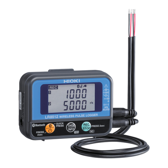
WIRELESS PULSE LOGGER
WIRELESS CLAMP LOGGER
WIRELESS HUMIDITY LOGGER
WIRELESS VOLTAGE/TEMP LOGGER
EN
Sept. 2018 Revised edition 5
LR8512B981-05 18-09H
Table of
Contents
Previous
Page
Next
Page
1
2
3
4
5
Advertisement
Table of Contents
Need help?
Do you have a question about the LR8512 and is the answer not in the manual?
Ask a question
Questions and answers
Related Manuals for Hioki LR8512
Data Loggers Hioki LR8512 Instruction Manual
Wireless pulse, clamp, humidity and voltage/temp loggers (185 pages)
Data Loggers Hioki LR8520 Instruction Manual
Wireless fungal logger (138 pages)
Data Loggers Hioki LR8431-20 Manual
Memory hilogger (37 pages)
Data Loggers Hioki LR8431-20 Instruction Manual
(204 pages)
Data Loggers Hioki LR8431-20 Measurement Manual
Portable handheld memory hilogger, heat flow logger (44 pages)
Data Loggers Hioki LR8431-20 Measurement Manual
Memory hilogger (32 pages)
Data Loggers Hioki LR8400-20 Instruction Manual
Memory hilogger (298 pages)
Data Loggers Hioki MEMORY HiLOGGER LR8400-20 Measurement Manual
(25 pages)
Data Loggers Hioki Memory HiLogger LR8401-20 Instruction Manual
(300 pages)
Data Loggers Hioki LR8410-20 Instruction Manual
Wireless logging station (364 pages)
Data Loggers Hioki LR8432-20 Instruction Manual
Heat flow logger (238 pages)
Data Loggers Hioki LR8450 Quick Start Manual
Memory hilogger (96 pages)
Data Loggers Hioki LR8450 Quick Start Manual
Memory hilogger (120 pages)
Data Loggers Hioki MEMORY HiLOGGER LR8450 Instruction Manual
(310 pages)
Data Loggers Hioki LR8101 Startup Manual
(58 pages)
Data Loggers Hioki LR8101 Instruction Manual
(363 pages)
This manual is also suitable for:
Lr8513
Lr8514
Lr8515
Lr8410
Table of Contents
Print
Rename the bookmark
Delete bookmark?
Delete from my manuals?
Login
Sign In
OR
Sign in with Facebook
Sign in with Google
Upload manual
Upload from disk
Upload from URL


Need help?
Do you have a question about the LR8512 and is the answer not in the manual?
Questions and answers