Table of Contents
Advertisement
Quick Links
Advertisement
Table of Contents

Related Manuals for Brunner DF 33


Summary of Contents for Brunner DF 33
- Page 1 Installation manual DF 33 ©2023...
-
Page 2: Table Of Contents
Setting of the maximum turn (motor controlled operation)............27 Installation of the flue pipe......................29 Assembly of the combustion chamber..................29 Installation of the deflector plate....................31 Air supply connection........................32 5.10 Flue outlet connection......................... 33 5.11 Finishing works..........................36 Drawings and technical data................(1.12) © 2023 Brunner GmbH... -
Page 3: Basic Informations
Fireplaces equipped with a water boiler must be pressure-tested after hydraulic connection to the heating system. Masonry work may follow only after this pressure test. Ulrich Brunner GmbH does not cover any costs incurred by necessary dismantling of masonry for rework at water boiler installation or replacement of the boiler. -
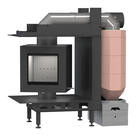
Page 4: Product Description
The lateral access underneath the DF fireplace does not ensure sufficient access to the rotating function mechanism! DELIVERY CONTENTS The delivery consists of different packaging units depending on the configuration of the system. (1.12) © 2023 Brunner GmbH... -
Page 5: Description Of Parts
Variable C frame with smoke pipe cover D028106-01 Masking kit 1 2 Variant B: D028136 C frame with masking kit 2 D028153 Variable C frame with smoke pipe cover D028129-01 Masking kit 2 3 Optional D028160 Rotating system with remote control © 2023 Brunner GmbH (1.12) -
Page 6: C Frame (D028153)
C FRAME (D028153) Item Part No. Designation D028151 C frame upper elongation assembly D028123 Welded niche support assembly 02080 Long adjustable foot complete assembly (1.12) © 2023 Brunner GmbH... -
Page 7: Complete Masking Kit (D028106-01 Or D028129-01)
COMPLETE MASKING KIT (D028106-01 OR D028129-01) Masking kit part no. Item Designation D028106-01 D028129-01 D028103-01 D028130-01 Upper cover assembly D028105-01 D028133-01 Rear cover assembly D028104-01 D028132-01 Lower cover assembly D028149-01 D028149-01 Lower cover insert © 2023 Brunner GmbH (1.12) -
Page 8: Cast Iron Parts
CAST IRON PARTS (1.12) © 2023 Brunner GmbH... - Page 9 Cast iron parts assembly D003221 Combustion air turntable 800168 Flat head screw M8x10 D028040-01 External bottom plate D028074 Air control lever assembly D003484 Air adjuster round handle assembly D028075 Air adjusting rod G022038 Air adjusting pusher © 2023 Brunner GmbH (1.12)
-
Page 10: Combustion Chamber Linings (D028020)
COMBUSTION CHAMBER LININGS (D028020) Item Part No. Designation D028023 Left side wall stone D028022 Rear wall stone D028025 Deflector D028024 Right side wall stone D028021 Bottom plate (1.12) © 2023 Brunner GmbH... -
Page 11: Door Assembly (D028019)
DOOR ASSEMBLY (D028019) Item Designation Part No. D028046-01 DF 33 door D028059 Upper door hinge D028052 External glass pane with holding frame 02543 Lens headed screw M4x6 D028063 Sealing rope for glass pane 2 D8x1510mm D028056 Internal glass pane D028055... -
Page 12: Adapter (Optional)
For smoke outlet connection with steel cover, MSS to the rear or top, the adapter part no. D028195 is re- quired. Im. 1: Component D028195 For smoke outlet connection with MAS 440 or the appicable ring, the adapter part no. D028194 is required. (1.12) © 2023 Brunner GmbH... -
Page 13: Installation
Im. 2: Component D028194 INSTALLATION SET UP Delivery condition: © 2023 Brunner GmbH (1.12) - Page 14 (1.12) © 2023 Brunner GmbH...
- Page 15 If there is a static load on the mounting frame, a bracing to the rear wall / ceiling is required. Points for fixing fixtures to the wall or to the ceiling (if necessary): © 2023 Brunner GmbH (1.12)
-
Page 16: Assembly
ASSEMBLY CAUTION Risk of injury during handling! We recommend that at least two people carry out the work. (1.12) © 2023 Brunner GmbH... - Page 17 Insert the enclosed bushings (see illustrations on the left) Screw on column with baseplate afterwards © 2023 Brunner GmbH (1.12)
- Page 18 Place sufficient cable length in the standpipe so that the cable can later be pulled into the body of the DF and connected to the cable from the door contact switch. Lift the DF with at least two people! Place scratch protection underneath (1.12) © 2023 Brunner GmbH...
- Page 19 Use a lever (see illustrations) to adjust the DF © 2023 Brunner GmbH (1.12)
- Page 20 Adjust the DF so that the three centring bolts on the underside engage (compare figures on the left) When the bolts are engaged, fasten the DF with 3 screws at the bottom (1.12) © 2023 Brunner GmbH...
- Page 21 The mechanism of the rotary move- ment below the DF must be accessi- ble for maintenance purposes. If the bottom cover is not used, accessibility must be ensured by the customer. © 2023 Brunner GmbH (1.12)
- Page 22 Fit the flue gas outlet and screw it on from the inside with three screws (1.12) © 2023 Brunner GmbH...
- Page 23 DF for mainte- nance purposes. If the air flap actuator is to be mounted be- low the C-frame, the retaining plate must be fitted. © 2023 Brunner GmbH (1.12)
- Page 24 (hole must be made on site).Please note that the thermocouple is accessible in case of spare parts. For the further steps, please observe the EAS / EOS assembly instructions! (1.12) © 2023 Brunner GmbH...
-
Page 25: Setting Of The Maximum Turn (Manual Operation)
SETTING OF THE MAXIMUM TURN (MANUAL OPERATION) maximum turn to the right: maximum turn to the left: © 2023 Brunner GmbH (1.12) -
Page 26: Electrical Connection Of The Rotary Function
The electrical components of the automatic lathe can be connected as shown opposite. The remote control is already coupled with the electronics at the factory. Optionally, a manual pushbutton can be con- nected in addition to the remote control. (1.12) © 2023 Brunner GmbH... -
Page 27: Setting Of The Maximum Turn (Motor Controlled Operation)
SETTING OF THE MAXIMUM TURN (MOTOR CONTROLLED OPER- ATION) Electric shock Only a qualified specialist is allowed to work on the electrical installation. The electri- cal connections are under mains voltage. This can lead to an electric shock. Observe all applicable regulations. © 2023 Brunner GmbH (1.12) - Page 28 (1.12) © 2023 Brunner GmbH...
-
Page 29: Installation Of The Flue Pipe
INSTALLATION OF THE FLUE PIPE ASSEMBLY OF THE COMBUSTION CHAMBER D028038 © 2023 Brunner GmbH (1.12) - Page 30 (1.12) © 2023 Brunner GmbH...
-
Page 31: Installation Of The Deflector Plate
D028038 INSTALLATION OF THE DEFLECTOR PLATE D028048 © 2023 Brunner GmbH (1.12) -
Page 32: Air Supply Connection
AIR SUPPLY CONNECTION (1.12) © 2023 Brunner GmbH... -
Page 33: 5.10 Flue Outlet Connection
Flue outlet connection with MSS mounted on top: Flue outlet connection with rear mounted MSS For a flue outlet connection with MAS 440 the adapter no. D028194 (matching the ring of the MAS) is necessary. © 2023 Brunner GmbH (1.12) - Page 34 IN THE VERSION WITH STEEL HOOD, WITH MSS REAR OR ON TOP After fixing the adapter, the installation of the re- spective flue outlet connection is carried out ac- cording to the applicable installation instructions: with rear mounted MSS: wiht MSS on top: (1.12) © 2023 Brunner GmbH...
- Page 35 Installation of the spacer ring adapter 10085.1 D028112 Note that for a later installation of the thermocouple the thermocouple connection (X) in the intermediate ring (10085.1) must point to the rear! R009095-01 R009042 R009042 R009042 10085.1 © 2023 Brunner GmbH (1.12)
-
Page 36: 5.11 Finishing Works
Installation of the cover panel for the flue tube casing Installation of cover panel and insert layer In order to be able to reach the mechanism for the rotational movement in the case of service work, the cover and insert must be removably installed! (1.12) © 2023 Brunner GmbH... - Page 37 © 2023 Brunner GmbH (1.12)
- Page 38 Dimension sheets - DF 33 DF 33 with niche cladding 01 DF 33 with niche cladding 01 Stand: 2023-09-04...
- Page 39 Dimension sheets - DF 33 DF 33 with niche cladding 02 DF 33 with niche cladding 02 Stand: 2023-09-04...
- Page 40 Dimension sheets - DF 33 DF 33 without niche cladding DF 33 without niche cladding Stand: 2023-09-04...
- Page 41 Dimension sheets - DF 33 Niche cladding 01 with MSS Niche cladding 01 with MAS Stand: 2023-09-04...
- Page 42 Dimension sheets - DF 33 Niche cladding 01 with GNF 8 We suggest for CAD planning Palette CAD. Permanent updated drawings: www.brunner.de Frames/ flue gas outlet connection/ combustion air supply connection/ front variants/ support bearing are marked in col- Stand: 2023-09-04...
- Page 43 Planning and installation - DF 33 Tested according to EN 13229 W EN 13229 WA Values measured at Rated power Storage operation Suitable for all construction types according to rules Data for functional demonstration Rated heat power Fire wood volume...
- Page 44 Technical and assortment changes as well as errors and Zellhuber Ring 17-18 misprints reserved. D-84307 Eggenfelden Reprinting and reproduction, even in part, only with the express permission of the publisher. Tel.: +49 (0) 8721/771-0 / Fax: +49 (0) 8721/771-100 Email: info@brunner.de Art.Nr.: 202017 (1.12) © 2023 Brunner GmbH...
Need help?
Do you have a question about the DF 33 and is the answer not in the manual?
Questions and answers