Table of Contents
Advertisement
Quick Links
Advertisement
Table of Contents

Related Manuals for Mooer GE1000


Summary of Contents for Mooer GE1000
- Page 1 GE1000 / GE1000 Li Intelligent Multi-Effects Owner’s Manual...
-
Page 2: Table Of Contents
CONTENT PRECAUTIONS ............................1 FEATURES ..............................2 CONTROLS ............................... 3 CONNECTIONS ............................5 TERMINOLOGY ............................6 CONNECTION SCENARIOS ........................7 Connection to Full-Range equipment ....................7 Connection to a guitar power amplifier and cabinet ................7 Mixed full-range / non-full-range device connection ................. 8 Four-Wire connection ......................... - Page 3 Use as Master Volume / Expression Pedal ..................25 Expression parameter mapping ....................25 Remove expression mappings ....................... 26 Toe switch mapping ........................26 USING EFFECT LOOPS ..........................27 Connecting a single effect pedal ....................... 27 4-Wire connection method ....................... 29 Extended input and output options ....................
- Page 4 GE1000 as controlled device ......................45 MIDI Channel ..........................45 CC Mapping ........................... 45 PC mapping ............................ 47 Other settings ..........................48 GE1000 as controlling device ......................49 MIDI Channel ..........................49 PC mapping ............................ 49 Other settings ..........................50 F4 WIRELESS FOOTSWITCH ........................
-
Page 5: Precautions
Connections Always turn off / disconnect the power to the GE1000 and any other equipment before connecting or disconnecting signal cables. This will help prevent malfunctions and / or damage to other devices. Also make sure to disconnect all connection cables and the power supply before moving the device. -
Page 6: Features
New member of MOOER GE series, using the new Walking Star design language • Choice between a traditional version (GE1000) and a version with integrated 7.4 V / 4750 mAh Li-Ion battery (GE1000 Li) for use without a power cable • Large 5" high-quality touch screen with intuitive UI, delivering brand-new multi-effect experience •... -
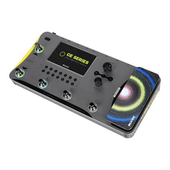
Page 7: Controls
CONTROLS 1. Power switch: Press for several seconds to turn the device on/off. 2. 5-inch LCD touch-screen: Shows presets, parameters and statuses and allows full operation of all features using touch commands. 3. Home button: Press to return to the main user interface. 4. - Page 8 8. Expression Pedal ) 9. Select knob: Encoder for fine-tuning parameters selected on the touch screen. Press to restore the respective default values. 10. Logo LED: Indicates the status of the EXP1 pedal. The pedal works as Expression pedal when the logo is lit and as Volume pedal when the logo is not lit.
-
Page 9: Connections
8. MIDI IN/OUT: 5-PIN MIDI connector. Use a 5-PIN MIDI cable to connect to an external device that can control the GE1000 or a device that can be controlled by the GE1000. 9. USB Type C interface: Connection to a computer for USB audio functions or to use the supporting software (See USB DIGITAL AUDIO , see 错误!未找到引用源。... -
Page 10: Terminology
(A-C). The 3 presets in each bank can be selected with the A, B or C footswitches. Effects chain: • The sequence of effects a signal has to pass through within the GE1000 to get from the input to the output. Effect module: •... -
Page 11: Connection Scenarios
This connection scenario includes a guitar amplifier with FX LOOP or a pure power amp. It is recommended to activate the AMP module when you establish connections using this application scenario. All preamp functions will be performed by the GE1000 in this case. Please refer to the following diagram for connections:... -
Page 12: Mixed Full-Range / Non-Full-Range Device Connection
This way, the preamp section of a physical amp can be positioned in the effect chain of the GE1000 using the Send / Return modules and the output of the GE1000 can then be run through the power amp section of the same amplifier. Please refer to the following diagram for connections:... -
Page 13: Quick Start
After the boot sequence is completed and the screen shows the main user interface, adjust MASTER volume to the appropriate volume Note: During the boot process, the GE1000 will load the last preset that was active before shutdown. Main user interface The GE1000 comes with two types of main interfaces: the STAGE VIEW and the EDIT VIEW. -
Page 14: Edit View
(Edit View) Edit View Almost all control functions of the GE1000 are concentrated in the Edit View user interface screen. This is where you access effect parameters for editing, bring up a list of presets, save presets, adjust global inputs and outputs, open the "Groove Station" or the Tuner, or access system settings and other features. -
Page 15: Preset Selection
Press the Power button for about 3 seconds until the message "Are you sure to Shut Down?" appears on the screen. Confirm the shutdown (YES) or cancel it (NO). Note for the GE1000 Li: If the power cable is still connected after shutdown, the screen will show a dimmed graphic to indicate the battery charging status. -
Page 16: Operation
Before you start editing, it is recommended that you open an empty preset (named 'EMPTY') to work with. Preset composition A preset in the GE1000 consists of the following components: • all effect models (modules) positioned in the current effect chain, •... -
Page 17: Dsp Resources
(e.g. red for DYNA, blue for MOD etc.) Note: The GE1000 effect chain is divided into two lines: A and B (the A/B designations are only relevant for MIDI mapping, see CC Mapping). Each line has 7 positions for effect modules, for a total of 14 effect modules. -
Page 18: Changing Effect Positions
Option 2: Select a module on the touch screen (highlighted by a frame) and press the SELECT knob to activate / deactivate the module. Option 3: Press the physical module button corresponding to the desired module. The first press opens the parameter editing interface. Every subsequent press on the same button toggles the selected module on/off. -
Page 19: Removing Effects
Option 2: Select a module on the touch screen (highlighted by frame) and rotate the SELECT knob to move the module. Removing effects If you need to remove an effect module from the effect chain of the current preset, long press the target module on the touch screen until the delete symbol (-) appears in the upper right corner of the module icon. -
Page 20: Parameter Editing
Touch the blank area above the effect chain on the touch screen to return to the normal state (the deletion icon disappears). Parameter editing Double click a module icon in the effect chain on the touch screen or press the corresponding physical module button to open the parameter editing interface. -
Page 21: Changing The Effect Model/Type
Use the MASTER knob to control the output level of all presets simultaneously. BPM tempo Some effects of the GE1000 such as DELAY and MOD modules have a time / rate parameter value that can be controlled by adjusting the BPM (Beats per Minute) value. See section Parameter editing for details on how to apply the BPM tempo to an effect parameter. - Page 22 The GLOBAL and PRESET options in this screen can be used to determine which presets the selected BPM tempo is applied to. Please make this choice before you change the tempo! If PRESET is selected, the tempo change is only effective for the current preset, and other presets can have different tempos.
-
Page 23: Saving Presets
You can use any of these four methods, or a combination of them, to quickly adjust the desired BPM tempo. Note: The speed range of GE1000 is 40 - 260 BPM. Tap the "X" in the upper right corner to return to the main Edit View. - Page 24 Preset selection) without saving your settings first, all changes will be lost and the preset will return to the previously saved settings the next time you select it. After adjusting all necessary settings, press the physical SAVE button on the panel or click the Save icon on the touch screen in Edit View to save your settings.
-
Page 25: Ai Equalizer
Alternatively, one of the footswitches can be configured for Tap Tempo input. The ▼, A, B and C footswitches of the GE1000 can each be configured to act as an ON/OFF switch for one of the effect modules within the current preset's effect chain or to act as a tap tempo input. -
Page 26: Activating The Ctrl Mode
Note: CTRL footswitch assignments must be saved with the preset. If you switch presets before you save the current preset, your CTRL assignments for the current preset will be lost. (See Saving presets) Activating the CTRL mode In Stage View or Edit View, one of the A, B or C footswitches will have its LED ring illuminated to indicate the currently active preset. - Page 27 The four footswitches in the lower row can now be used to perform the selected functions for as long as the CTRL mode is active. (See F4 WIRELESS FOOTSWITCH for additional options.) You can leave the CTRL mode and return to Stage View or Edit View by pressing the BANK ▲...
-
Page 28: Expression Pedal
Expression Pedal The GE1000 is equipped with an on-board rocker pedal that can be used as volume pedal (default) or as an expression pedal to control multiple modules and parameters. You need to calibrate the GE1000's pedal before you use it for the first time. -
Page 29: Use As Master Volume / Expression Pedal
EXP1 pedal (firmly pressing down on the front). When the GE1000 Logo light is off, the pedal will operate as a master volume control. When the GE1000 Logo light is on, the pedal will operate as expression control. -
Page 30: Remove Expression Mappings
• Click the pedal icon at the bottom of the Edit View to open the expression pedal settings screen. • Click PARAMETERS on the left side. All pedal mappings for the current preset will be listed. • Click the parameter you want to modify, and adjust the values by sliding the bars or by rotating the SELECT knob. -
Page 31: Using Effect Loops
USING EFFECT LOOPS The GE1000 is equipped with jacks for a single-port stereo effect loop. This means that the SEND and RETURN jacks of the FX LOOP not only support the connection of mono devices, but can also be used to connect to external stereo devices using Y-format audio cable adapters. - Page 32 "FX LOOP" with type "FX LOOP". This setting is suitable for most external effects that can be embedded in the GE1000 effect chain. The actual signal flow is shown in the figure below:...
-
Page 33: 4-Wire Connection Method
A connection scenario in a previous chapter has already introduced the four-wire connection method (see Four-Wire connection). This section explains the necessary module settings in the GE1000. As the name suggests, the four-wire connection method refers to two devices with effect loop capabilities connected to each other using four audio cables. - Page 35 (i.e. in the effects loop of the amplifier = post-effects). You can achieve this scenario with the following setup in the GE1000's FX LOOP: • Connect the GE1000 and the amplifier as shown in the connection diagram above.
-
Page 36: Extended Input And Output Options
Scenario 1: Auxiliary Audio Input (AUX IN) • Add the FX RETURN module to the GE1000 effect chain. • Move it to the appropriate position or to the very end of the effects chain if you don't want the incoming audio to pass through any internal effect modules. -
Page 37: Tuner
Scenario 2: Expanded output mode (e.g. different outputs with or without cab simulation) • Add the FX SEND module to the GE1000 effect chain. • Move it before the CAB module in the effect chain. • Select the FX SEND module mode as "Parallel" and the wet/dry ratio as "50:50". -
Page 38: Tuning
Click the field in the lower left corner or press the SELECT knob to switch between BYPASS tuning mode or MUTE tuning mode. BYPASS tuning disables the internal effects and sends a clean signal to the outputs for as long as the tuning mode is active. -
Page 39: Groove Station Screen
Groove Station screen The five large square icons in the Groove Station screen indicate the footswitch functions that will be performed when the footswitch is pressed the next time. You can click the squares on the touch screen or press the corresponding footswitches to perform the functions. The icons at the top indicate the REC/PLAY/STOP/REDO/UNDO status of the Looper. -
Page 40: Looper
Looper The GE1000 features a Looper with up to 8 minutes of recording time, overdubbing function and independent level control. Footswitch ▼: REC / PLAY / DUB / UNDO / REDO • Tap once for Record, tap again for Play, tap again for Dub…... -
Page 41: Close The Groove Station
Normal mode: You can use the GE1000 like an external sound card. The input will be automatically taken from the input jack of GE1000 (your guitar), and the output will be sent to the USB output port (digital signal) from the GE1000 to your computer. -
Page 42: Mode Descriptions
Mix Ratio: Adjusts the mix ratio between hard and soft monitoring. A setting all the way to the left means that 100 % of the signal is coming from the GE1000 (hard monitoring). All the way to the right means that the 100 % of the signal comes from the computer/DAW/plug-in, etc. -
Page 43: Bluetooth Audio
(pre-recorded or other audio track), the other one should be a blank track. • Play the dry track through the GE1000 DSP effects and make sure the input level indication in the PC software shows no distortion (clipping). Adjust the level with Record level. -
Page 44: Global Settings
(boost, overdrive, distortion …) in front of the GE1000. You can get visual confirmation of the input level by watching the input level indication bar on the screen or by watching the input level LED at the beginning of the row of physical effect module buttons. -
Page 45: Global Output Volume
1. Global output volume You can use this page to set the output volume for each output interface individually, including the 1/4" output ports, the XLR output ports, the headphone jack and the USB digital recording output. Use these settings to establish the relative volume ratio between the different outputs. The MASTER knob on the pedal will increase/decrease all outputs at the same time, but will maintain the ratios established here. -
Page 46: Screen Brightness
According to test statistics, the battery life of the GE1000 Li (battery version) can be extended by almost one hour with 50% brightness instead of 100% and otherwise identical usage conditions. -
Page 47: Tap Tempo
Tap Tempo This setting controls how the tap tempo input is used within the GE1000. When set to "Global", all presets are effected by a tap tempo input, when set to "Preset" every individual preset can have its own tap tempo input. You can also click the "Metronome" in the Edit View to access the same settings. -
Page 48: Factory Reset
Looper audio: All audio recordings made with the Looper function will be deleted. MIDI The GE1000 is equipped with a 5-pin MIDI interface, and can be configured to send MIDI commands (MIDI OUT) or to receive them (MIDI IN). MIDI settings are global settings and apply to all presets. -
Page 49: Ge1000 As Controlled Device
GE1000 as controlled device To configure the GE1000 as a controlled device, press the SETTINGS knob, scroll down to MIDI, select "Slave" and click "Settings" to enter the configuration page. The following options are provided: MIDI Channel Click CHANNEL and select the MIDI command channel that the GE1000 is supposed to respond to. - Page 50 This corresponds to controlling the PATCH LEVEL (preset volume) in the Edit View. Tap Tempo 0 - 127 This command is sent to the GE1000 continuously, and the interval is used as the value for the tempo setting. Input level 0 - 127 Controls the input volume in the Global Input settings.
-
Page 51: Pc Mapping
PC mapping This list corresponds to the preset numbers that can be controlled by PC codes from two MIDI banks (0 and 1). The individual settings can be changed by the user. List of default factory settings: MIDI Preset MIDI Preset MIDI Preset... -
Page 52: Other Settings
MIDI Preset MIDI Preset MIDI Preset MIDI Preset PC code PC code PC code PC code bank bank bank bank Other settings Use this page to activate/disable MIDI CLOCK SYNC for incoming MIDI commands and to activate/disable USB MIDI. MIDI Clock: When active, tempo-based features of the main Edit View will be synchronized to the MIDI clock commands sent by the external device. -
Page 53: Ge1000 As Controlling Device
The factory default is Channel 1. PC mapping This list corresponds to the PC codes in two MIDI banks (0 and 1) that the GE1000 can send. The individual settings can be changed by the user. After switching to a preset, the GE1000 will send CC0 (MIDI bank information) + the PC command to the receiving device. -
Page 54: Other Settings
Use this page to activate/disable MIDI CLOCK SYNC for outgoing MIDI commands and to activate/disable USB MIDI. MIDI Clock: When active, MIDI clock commands are sent out based on the GE1000's current BPM tempo. USB MIDI: Enable this feature to send MIDI commands through the USB-C interface. -
Page 55: F4 Wireless Footswitch
After pairing is completed, the wireless footswitch can be used to switch the four CTRL functions assigned to the current preset (see CTRL ). The GE1000 does not have to be in CTRL mode for this. This means that, depending on the functions you have assigned for this preset in CTRL mode, you can use the wireless footswitch at any time to individually activate/deactivate up to four effect modules in the chain of the currently selected preset or to control the tap tempo. -
Page 56: Troubleshooting
Check that the "PATCH LEVEL" is properly set. • Check whether the EXP1 pedal is in volume mode (the GE1000 logo light on the left side of the pedal is off), and move the pedal to the "toe down" position. -
Page 57: Specifications
SPECIFICATIONS Effects Number of module types Total number of effect models more than 280 Preset storage slots Impulse Response Supported formats Sampling rate 44.1 kHz Sampling accuracy 24 bit Number of sample points Up to 2048 sampling points Inputs INPUT jack Interface type 1 x 1/4'' unbalanced mono input connector Input impedance... - Page 58 TYPE-C connector General Power Supply GE1000: DC 9 V, 1 A, negative center GE1000 Li: DC 9 V, 3 A, negative center Battery (GE1000 Li) Li-ion, rechargeable, 4750 mAh, 35.15 Wh, 7.4 V Battery life (GE1000 Li) Approx. 6 hours (at 50% screen brightness, 25°C) Charging time (GE1000 Li) Approx.
-
Page 59: Annex 1: Effect Descriptions
Blood Comp Three parameter compressor with adjustable blend ratio. Noise Killer Hard noise gate based on the Mooer® Micro Noise Killer. The effect solves noise issues quickly and efficiently with simple threshold adjustments. Intel Reducer Unlike conventional noise gates, this works by separating the conventional signal from the white noise in the signal and eliminating the white noise to achieve noise reduction while maintaining natural decay. -
Page 60: Filter Modules
Modulated automatic sweeping Wah. Touch Wah Dynamic envelope filter auto Wah. Talk Wah Ah Talking Wah algorithm from the MOOER® Red Kid. Talk Wah Oh Talking Wah algorithm from the MOOER® Red Kid. Low Pass Filter Static low frequency pass filter. -
Page 61: Overdrive Modules
Overdrive modules Effect Description Model name Description Pure Boost Based on MOOER® Pure Boost Flex Boost Based on MOOER® Flex Boost Tube DR Based on B.K. Butler® Tubedrive Based on IBANEZ® TS808 OD250 Based on DOD®... -
Page 62: Amplifier Modules
Amplifier modules Effect Description ( Classic ) Model name Description 65 US DLX Based on Fender® 65 Deluxe Reverb (preamp only) 65 US TW Based on Fender® 65 Twin Reverb (preamp only) 59 US BASS Based on Fender® 59 Bassman (preamp only) US Sonic Based on Fender®... - Page 63 Carol OD Based on Two Rock® Coral Overdrive Setting (preamp only) EV 5050 DS Based on EVH® 5150 Distortion Setting (preamp only) Ht Club DS Based on Blackstar® HT Stage 100 Distortion Setting (preamp only) Hugen OD Based on Diezel® Hagen Overdrive Setting (preamp only) Hugen DS Based on Diezel®...
-
Page 64: Poweramp Modules
US DLX 6l6 Based on Fender® Blues Deluxe power tube. JJ el84 Based on JJ® EL84 power tube. Baby Bomb Based on Mooer® Baby Bomb. Parameter Description Parameter name Description Power Amp Input Adjusts the input level of the power amp. -
Page 65: Cabinet Modules
Note: The names of the manufacturers and products covered in this manual are the property of their respective companies, and are used here only for the purpose of illustrating the types of effect tones simulated in this product. Cabinet modules Effect Description (Classic) Model name Description... -
Page 66: Equalizer Modules
Description 3 bands EQ Simple amp style 3-band EQ. 5 Bands EQ Simple amp style 5-band EQ. MOOER HM Stompbox style 5-band EQ for heavy guitar. MOOER B Stompbox style 6-band EQ for guitar. MOOER G6 Stompbox style 6-band EQ for guitar. -
Page 67: Fx Loop Module
Description Fx Loop Module that can be used to integrate your favorite external effects and preamps into the signal chain, or to integrate the GE1000 into creative and complex setups. Fx Send The normal Fx Loop module with only the "Send" function, you can use it to send the internal signal to an external device. -
Page 68: Modulation Modules
Modulation modules Effect Description Model name Description Phaser Based on the MOOER® Ninety Orange. Step phaser Square wave phase shifter. Fat Phaser Low frequency phase shifter. 6 Stage Analog Six stages phase shifter. Phaser 12 Stage Analog Twelve stages phase shifter. -
Page 69: Time Delay Modules
Rise Adjusts the time needed for the volume to reach its maximum. 100 is the slowest. Sweep Moves the frequency response pattern through a six-octave or twelve- octave range. Resonance Changes the amplitude and sharpness of the frequency response peaks. Delay Sets the delay time for the flanger. -
Page 70: Reverb Modules
High Cut Sets a high frequency EQ shelf for the delay repeats. Low Cut Sets a low frequency EQ shelf for the delay repeats. Threshold Sets the envelope detection level of the dynamic delay. Mod Output Adjusts the output level of the modulation. Filter (lp/bp/hp) Choose the type of the filter envelopes. - Page 71 Filter Level Adjusts the volume level of the filter applied to the reverb trails. Feedback Adjusts the feedback intensity of the flanging. Mod-Delay Adjusts the feedback frequency of the flanging Attack Rate of automatic volume swell of the reverb effect. 100 is the fastest. Gain Adjusts amount of distortion.
Need help?
Do you have a question about the GE1000 and is the answer not in the manual?
Questions and answers