
Related Manuals for J&M Speed Tender Pro


Summary of Contents for J&M Speed Tender Pro
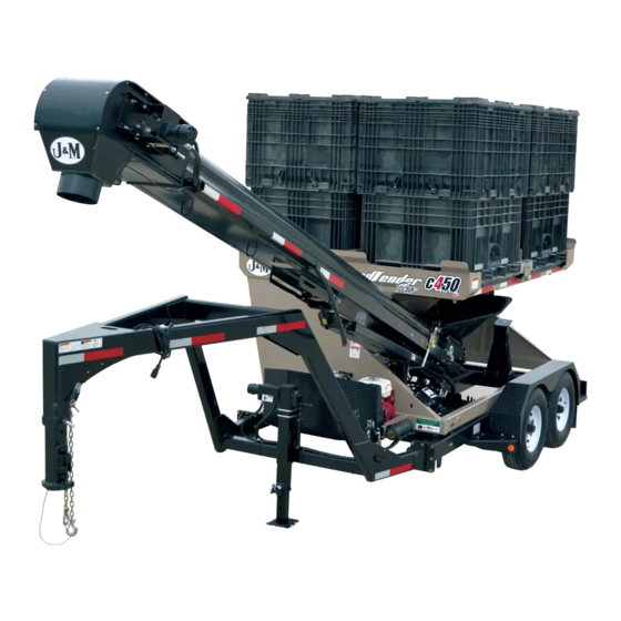
- Page 1 Manual p e e d e n d e r MODEL O P E R A T O R ’ S M A N U A L J&M Manufacturing Co, Inc 284 Railroad Street - P.O. Box 547 | Fort Recovery, OH 45846 | Ph: (419) 375-2376 | Fax: (419) 375-2708 www.jm-inc.com...
-
Page 3: Table Of Contents
Table Of Contents To the Dealer ................. . . 4 General Information . -
Page 4: To The Dealer
To the Dealer TO THE DEALER Read manual instructions and safety rules. Make sure all items on the Dealer’s Pre-Delivery and Delivery Check Lists are completed before releasing equipment to the owner. The dealer must complete the Warranty Registration found on the Dealer Portal website located at dealer.jm-inc.com and return it to J&M Mfg. -
Page 5: General Information
General Information TO THE OWNER: The purpose of this manual is to assist you in operating and maintaining your seed tender in a safe manner. Read it carefully. It furnishes information and instructions that will help you achieve years of dependable performance and help maintain safe operating conditions. If this machine is used by an employee or is loaned or rented, make certain that the operator(s), prior to operating: 1. -
Page 6: Safety Rules
Safety Rules Understand that your safety and the safety of other persons are measured by how you service and operate this machine. Know the positions and functions of all controls before you try to operate them. Make sure to check all controls in a safe area before starting your work. -
Page 7: Specifications
Specifications Weight Tongue Weight Unloading Capacity (Total) (Empty) (Loaded) Conveyor Rate Conveyor Axles Engine 4 (Four), 50 Unit Boxes 6,300 lbs 1,650 lbs 22’ Long, 30 Bushels/ 49’ (Front to Two (2), 7,000 lb. 13 HP Honda (200 Total Units) 8”... -
Page 8: Decals
Decals Description Part No. SpeedTender Pro c450 Stripe Decal JM0051244 Warning, Do Not Adjust Or Service Decal JM0014979 Danger, Electric Lines Decal JM0015099 Warning, High Pressure Fluid Hazard Decal 4” x 4” JM0010163 Warning, Keep Open Flames Away Decal JM0014983 Run Engine At Full Throttle To Charge Battery Decal JM0032425 Warning, Always Use Safety Chains Decal JM0014995... - Page 9 Decals...
-
Page 10: Bolt Torque Specifications
Bolt Torque Specifications Always tighten hardware to these values unless a different torque or tightening procedure is listed for specific application. Fasteners must always be replaced with the same grade as specified in the manual parts list. Always use the proper tool for tightening hardware. Make sure fastener threads are clean and you start thread engagement properly. -
Page 11: Operations
Operations Preparing the Towing Vehicle Before towing the SpeedTender Pro, refer to towing vehicle’s operator’s manual for information concerning hitch capacities, hitch adjustments, and tire inflation. Towing vehicle must be equipped with proper electric braking components. NOTE: The SpeedTender Pro is equipped with LED lights. The towing vehicle may require a flasher upgrade for lights to operate properly. - Page 12 Operations Hydraulic Power Unit Operation Ensure all fittings and hardware are in proper operating condition. Replace if worn or broken. Check engine fluid levels and sight gauge on reservoir for proper operating levels. Slide the fuel shut-off lever to the “ON” position. Slide choke to the “ON”...
- Page 13 Operations Attaching the Bulk Seed Boxes WARNING: The Speed Tender Pro must be hooked to the towing vehicle during loading and unloading. WARNING: Load the front bulk seed boxes first to help prevent the chance of flipping. Unlatch and flip open all four of the lids.
- Page 14 WARNING: The Speed Tender Pro must be hooked to the towing vehicle during loading and unloading. Position the Speed Tender Pro next to the planter/drill so the conveyor will reach the planter box. Turn switch on battery disconnect to “ON”.
- Page 15 Operations Use the handheld controller or wireless remote to start the conveyor. Fill the planter/drill to desired level then repeat. NOTE: Adjusting engine throttle will regulate conveyor speed. 10. Close door on SpeedTender Pro before the last planter seed box is full so you can completely empty collapsible hopper and conveyor.
-
Page 16: General Service
General Service Daily Service (5 -10 Hours of Use) NOTE: J&M recommends the following service to be performed daily (every 5-10 hours of use) Grease the conveyor bearings every 10 hours. Use only two pumps of grease per bearing. NOTE: Excess lubrication of these bearings will result in premature failure. NOTE: The conveyor has four bearing that need greased (two at each end). -
Page 17: Hydraulic Power Service
General Service Removing From Storage Grease the conveyor bearings. Use only two pumps of grease per bearing. NOTE: Excess lubrication of these bearings will result in premature failure. NOTE: The conveyor has four bearings that need greased (two at each end). See “Conveyor Service” on page 20. Grease pivot points on boom arm. -
Page 18: Tire Service
Tire Service Tire Pressure The following is to be used as a general guide for tire inflation. Figures can vary depending on specific brand of tire used. It is important that tires are inspected before and after unit is loaded. Start with the minimum pressure indicated. The tire should stand up with no side wall buckling or distress as tire rolls. -
Page 19: Wheel Bearing Service
Wheel Bearing Service Clean, inspect, and repack the wheel bearings every 12 months or 12,000 miles. Use a number 2 wheel bearing grease to repack the bearings. Bearing Inspection and Service: Jack up SpeedTender Pro. Remove wheel lug nuts. Remove wheel from hub. Remove grease cap. -
Page 20: Conveyor Service
Conveyor Service Grease Conveyor Bearings Grease Point Grease the conveyor bearings every 10 hours of operation and before storage. Use only two pumps of grease per bearing. NOTE: Excess lubrication of these bearings will result in premature failure. NOTE: The conveyor has four bearings that need grease (two at each end). Grease Swing Arm Grease pivot points on boom arm every 50 hours and before storage. - Page 21 Conveyor Service Adjusting Conveyor Belt Tracking Loosen, but do not remove, the four bolts on the two bearing mounting plates located at the collapsible hopper end of the conveyor (as shown in the picture below). NOTE: Only adjust conveyor in normal position, do not adjust in self-fill position. Operate the conveyor at a slow speed.
-
Page 22: Brakes Service
Brakes Service The SpeedTender Pro is equipped with electric brakes. They need to be inspected and serviced immediately if a loss of performance is experienced. You need to service your SpeedTender Pro brakes at least once a year with normal use. How to use your electric brakes properly: Your SpeedTender Pro brakes are designed to work in synchronization with your tow vehicle brakes. - Page 23 Brakes Service Brake Shoe and Lining Inspection: A simple visual inspection of your brake linings will tell if they are usable. Replacement is necessary if the lining is worn (to within 1/16” or less), contaminated with grease or oil, or abnormally scored or gouged. Hairline heat cracks are normal in bonded linings and should not be cause for concern.
- Page 24 Brakes Service Voltage in the system should begin at 0 volts. As the controller bar is slowly actuated, the voltage should gradually increase to approximately 12 volts, which is referred to as modulation. No modulation means when the controller begins to apply voltage to brakes, it applies an immediate high voltage, which causes the brakes to apply instantaneous maximum power.
-
Page 25: Troubleshooting
Troubleshooting Problems Solutions Unit sways during travel a. Check tire pressure. b. Check tow vehicle for loosened hitch parts. c. Check tow vehicle’s hitch height. d. Reduce towing speed. e. Check wheel lug nuts. f. Check wheel bearings for adjustment (see ”Wheel Bearing Service” on page 19). Tires show excessive wear a. -
Page 26: Throttle Control For Kar-Tech
Troubleshooting Problems Solutions Excessive wear to belt edge - Rubber skirting is a. Replace rubber skirting. worn or out of place b. Adjust rubber skirting. Boom arm will not move up or down - Engine RPM a. Increase engine RPM. slow Boom arm will not move up or down - Hydraulic a. -
Page 27: Function Manifold Valve Schematic (Aluminum)
5 - Function Manifold Valve Schematic (Aluminum) Letter Function Conveyor Swing Front Conveyor Swing Rear Conveyor Up Conveyor Down Rear Door Up Front Door Down Power Front Door Up Rear Door Down Connector Conveyor Conveyor Start Conveyor Conveyor Front Rear On/O Up/Down Swing... -
Page 28: Wired Controls And Scale Monitor
Wired Controls and Scale Monitor Scale Option Items Note: When replacing Conveyor On/Off switch, both JM0028114 & JM0037125 will work. If operator wants to switch between on and off, select JM0028114. If operator wants to only run conveyor while holding the switch, select JM0037125. Description Part No. -
Page 29: Kar-Tech Wireless Controls And Scale Monitor
Kar-Tech Wireless Controls and Scale Monitor Throttle Control Option for Scale Option Wireless Control Items 14 Pin Connector Kar-Tech Remotes Items Toggle to Valve Bank Switch Harness Ground Power for Wireless Indicator Serial Port Throttle for Indicator Control On-Board Controller Wireless Receiver to Scale Indicator Valve Bank Harness for... -
Page 30: Intercomp Wireless Controls And Scale Monitor
Intercomp Wireless Controls and Scale Monitor 16030 WC3-D PRINT START HOLD EXPORT LIGHTS TALC SCALE POSITION ENGINE MENU STOP SETUP LEFT CONV RIGHT TARE CONTROLS CONTROLS CONTROLS GROSS DOWN OPEN DOOR 1 DOOR 2 ROLL TARP DOWN DOWN SHIFT CLOSE OPEN CLOSE SHIFT... -
Page 31: Lights And Wiring
Lights and Wiring This table will be used for the following section, Lights and Wiring, on Pages 31-34: Description Part No. 2-1/2” Red Round LED Light/Reflector Assembly (RRLA1) JM0001905 2-1/2” Red Round LED Light/Reflector (RRLR1) JM0001901 Round Grommet for LED 2-1/2” Light/Reflector JM0001902 2-1/2”... - Page 32 Lights and Wiring To Rear Top ST Main Harness (419-475) (JM0033700) To A-Frame or Harness Gooseneck Harness To Right Front To Rear Brake Light Marker Right Round Lights Red Marker To Electric Brakes Light To Onboard To Scale Box Valve Bank Controller Indicator Power...
- Page 33 Lights and Wiring ST Front Chassis Wiring Harness (419-385) (JM0019963) White 3” 30” 8” 3” To Front Top Harness 43” 65” To Front Lower Marker Light To Front Lower Marker Light ST Rear Top Lights Harness (419-390) (JM0019964) White 118” 7”...
- Page 34 Lights and Wiring V-Belt A-Frame 7-Way Trailer Connection (JM0046142) V-Belt Gooseneck 7-Way Trailer Connection (JM0046143) 150” 167” 3” 16” To Main Harness Light Blue 12V Battery Tail Lights Dark Blue Brown Left Turn & Brake Right Turn & Brake Green Yellow Breakaway Switch with Cable (BAS-1) Electric Brakes...
-
Page 35: Scale Display Box
Scale Display Box Description Part No. Chrome T-Handle Non-Locking JM0001911 Seed Tender Scale Box Door (LC Series) JM0046652 1/2” Shoulder Dia x 3/8” Shoulder Length x 3/8”-16 Socket Shoulder Bolt JM0009998 3/8”-16 Gr2 Z Centerlock Hex Nut JM0001512 Seed Tender Scale Box JM0046678 3/8”-16 x 1”... -
Page 36: A-Frame And Hitch
A-Frame and Hitch Description Part No. 5/8”-11 x 2” Gr8 Z Hex Bolt JM0001771 5/8”-11 Gr2 Z Centerlock Hex Nut JM0002146 Seed Tender - Chassis A-Frame Weldment JM0002481 5,000 lb Max Lift Capacity Jack (TWL-178T) JM0001480 1/4” x 3/4” Self Tapping Screw JM0001570 Breakaway Switch with Cable (BAS-1) JM0001843... -
Page 37: Gooseneck
Gooseneck 10 11 14 15 Description Part No. 12,500 Lb Safety Chain (SCST375) JM0015061 Square Gooseneck Coupler Tube 30,000 LB CAP JM0007076 Gooseneck Frame Weldment for Seed Tenders Less than 500 Seed Units JM0029497 Gooseneck Manual Jack with Custom Mounting Plate (10,000#) JM0007078 5/8”-11 x 2”... -
Page 38: 7K Axle
7k Axle 12 13 Aluminum parts and rim look like the one shown below. Description Part No. Rubber Plug for Dust Cap JM0039538 Dust Cap for EZ Grease (7,000lb) JM0035957 Aluminum Wheel Dust Cap JM0049437 9/16”-18 Conical Lugnut (4WS) (ST) JM0008525 9/16 RH 7/8 Hex 2.40 XL (Lug Nut to Aluminum Wheel) JM0044721... -
Page 39: Chassis
Chassis Description Part No. Driver Side Front Fender Bracket JM0068793 Passenger Side Front Fender Bracket JM0068794 Rear Passenger Side Fender Mount (SpeedTender) JM0002490 SpeedTender Pro Bumper JM0020862 Rear Driver Side Fender Mount (SpeedTender) JM0002491 Two Wheel Diamond Plate Fender Weldment (71”) JM0005874 235-85-R16 Load Range E Tire JM0003232... -
Page 40: Hydraulic Door
Hydraulic Door Description Part No. 1/2”-13 Gr2 Z Centerlock Hex Nut JM0001511 1/2”-13 x 1-1/2” Gr5 Z Hex Bolt JM0002100 Hydraulic Door Weldment c450 (HDST375W) JM0002872 3/8”-16 Gr2 Z Centerlock Hex Nut JM0001512 Hydraulic Door Weldment (290, 390, c450) JM0002883 3/8”-16 x 1”... -
Page 41: Spare Tire Mount
Spare Tire Mount Description Part No. 1 9/16” USS Flat Washer JM0050968 2 9/16”-18 Conical Lugnut (4WS) (ST) JM0008525 3 9/16”-18 x 7-1/2” Full Thread Stud JM0010068 Windows Description Part No. Window Seal 3/4” ‘S’ Strip JM0000254 Standard Inspection Window JM0000255... -
Page 42: Spout Options
Spout Options Description Part No. 1 36” Flex Hose and Clamp - ST390FH-36 JM0081725 2 8” x 11’ Long Telescoping Spout with Handle, Clamps, and Carabiner Assembly JM0081724 3 8” Telescoping Spout Sock JM0080479 4 Clamp for 8” Telescoping Spout (8C2SS) JM0002870 5 3/8”-16 Gr2 Z Centerlock Hex Nut JM0001512... -
Page 43: Conveyor Discharge End
Conveyor Discharge End 12 13 Description Part No. WR Series Hydraulic Motor with Keyway and Pinhole (15100F30N6AAAAA) JM0010469 Seal Kit for 15100F30N6AAAAA WR Series Hydraulic Motor JM0042773 Hydraulic Motor Mount (DMST375W) JM0002225 1/2” Shoulder Dia x 3/8” Shoulder Length x 3/8”-16 Socket Shoulder Bolt JM0009998 1/4”-20 x 3/4”... -
Page 44: Conveyor Idler End
Conveyor Idler End... - Page 45 Conveyor Idler End Description Part No. Conveyor Hopper Support Tube JM0040345 3/8”-16 x 1-1/4” Gr5 Z Carriage Bolt JM0001639 Conveyor Guard Weldment JM0002466 Inner Rubber Clamp-Hopper End 1-1/4” x 21-5/8” (1142158P) JM0002767 3/8”-16 x 1” Gr5 Z Carriage Bolt JM0001632 8”...
-
Page 46: Covers And Lids
Covers and Lids Description Part No. c450 Rubber Skirt for Lids JM0035220 c450 Cover Weldment Front Passenger Side JM0034520 c450 Cover Weldment Front Driver Side JM0034510 Lids for Cover Weldment c450 JM0034535 1/4”-20 x 3/4” Gr5 Z Hex Bolt JM0001507 1/4”... -
Page 47: Box Latches
Box Latches Description Part No. Front Clamp Bar c450 JM0033360 Side Latch Weldment c450 JM0035194 Rear Clamp Bar c450 JM0033375 1/4” Diameter Snap Ring JM0001870 3/8”-16 x 1” Gr5 Z Carriage Bolt JM0001632 SpeedTender Pro Lock Down Bolt-on Plate JM0020505 3/8”-16 Gr5 Z SF Hex Nut JM0002152 3/8”... -
Page 48: Swing Arm
Swing Arm Description Part No. 1” x 3-3/8” Hydraulic Cylinder Pin JM0010103 Single Swing Link c450 JM0002252 1”-8 Gr5 Z Nylon Locking Hex Nut JM0002161 1” x 2-1/4” Pin with Head and Cotter Pin JM0010201 Dual Swing Link c450 JM0002260 Battery Disconnect Description Part No. -
Page 49: Boom Arm
Boom Arm Description Part No. 1”-8 Gr2 Z Centerlock Hex Nut JM0002149 1”-8 x 9” Gr8 Z Hex Bolt JM0001708 Boom Arm c450 JM0041093 1/2”-13 x 6” Gr5 Z Hex Bolt JM0016679 1/2”-13 Gr2 Z Centerlock Hex Nut JM0001511... -
Page 50: Boom Rests
Boom Rests Description Part No. 1/4” Diameter Snap Ring JM0001870 Boom Rest Weldment (275, c450) JM0005876 1/2”-13 x 1-3/4” Gr5 Z Hex Bolt JM0002101 1/2”-13 Gr5 Z SF Hex Nut JM0002153 3/8”-16 Gr2 Z Centerlock Hex Nut JM0001512 12” x 2” Dock Bumper JM0001890 3/8”-16 x 1”... - Page 51 Hydraulic Motor Assembly 2024 - Current Description Part No. Pressure Gauge 0-3000 PSI (P562713) JM0037742 #4 Male SAE ORB x 1/4” Female Pipe 90 Deg Elbow JM0085124 1/2” Male JIC x 5/8” Male ORB; 90 Degree Elbow JM0039215 LENZ Tank Hydraulic Oil Screen (LTMA-10-100) JM0084748 1/2”...
-
Page 52: Hydraulic Jack
Hydraulic Jack U-Bolts used only on A-Frame Use the images to determine which seal kit is right for you. JM0037895 JM0082369 12 13 14 15 Parts here are specifically for a blue valve. When installing a hydraulic jack you will need to add this valve to the end of the conveyor... - Page 53 Hydraulic Jack Description Part No. 3” x 24” x 1-1/2” Welded Cylinder (JD324) JM0019644 Seal Kit 3” x 24” Cylinder (JD324-1) (JD480) JM0037895 Seal Kit for 3” x 24” Hydraulic Cylinder (30024-SK) JM0082369 5/8”-11 x 1-1/2” Gr5 Z Hex Bolt JM0002103 5/8”-11 Gr2 Z Centerlock Hex Nut JM0002146...
-
Page 54: Silver Hydraulic Valve Jm0029973
Silver Hydraulic Valve JM0029973 Swing Cylinder Rear Door Front Door Cylinder Cylinder Boom Cylinder 2024 and older 2024 and newer models will have this models will have this... - Page 55 Silver Hydraulic Valve JM0029973 Description Part No. Use these images to determine which seal kit you need. 1/2” x 210” Hydraulic Hose 210inch8M3k-8G-8FJX-8G-8FJX JM0041443 7. 1-1/2” Bore x 7” Cylinder 1/2” Male JIC x 1/2” Male JIC; Straight JM0041452 JM0046352 JM0084324 1/2”...
-
Page 56: Gold Hydraulic Valve Jm0080426
Gold Hydraulic Valve JM0080426 Swing Cylinder Rear Door Front Door Cylinder Cylinder Boom Cylinder... - Page 57 Gold Hydraulic Valve JM0080426 Use these images to determine Description Part No. which seal kit you need. 1/2” x 210” Hydraulic Hose 210inch8M3k-8G-8FJX-8G-8FJX JM0041443 7. 1-1/2” Bore x 7” Cylinder 1/2” Male JIC x 1/2” Male JIC; Straight JM0041452 JM0046352 JM0084324 1/2”...
-
Page 58: Blue Hydraulic Valve Jm0080825
Blue Hydraulic Valve JM0080825 Swing Cylinder Rear Door Front Door Cylinder Cylinder Boom Cylinder... - Page 59 Blue Hydraulic Valve JM0080825 Description Part No. Use these images to determine which seal kit you need. 1/2” x 210” Hydraulic Hose 210inch8M3k-8G-8FJX-8G-8FJX JM0041443 7. 1-1/2” Bore x 7” Cylinder 1/2” Male JIC x 1/2” Male JIC; Straight JM0041452 JM0046352 JM0084324 1/2”...
-
Page 60: Talc Applicator
Talc Applicator 11 10 Hydraulic Valve Mount... - Page 61 Talc Applicator Description Part No. 3/16” Nylon Rod for Talc Agitator JM0062689 3/4” Shoulder Dia x 1” Shoulder Length x 5/8”-11 Hex Head Shoulder Bolt and Nut (SB-34) JM0003181 3/4” ID x 7/8” OD x 5/8” LG Bronze Bushing (BB-34) JM0009455 Large Talc Box Screen (Electric &...
-
Page 62: Talc Hydraulics Schematic For Silver And Gold Valve
Talc Hydraulics Schematic for Silver and Gold Valve Hydraulic Motor Aluminum Valve Bank c4•50 Model Conveyor Return Hose Flow Control To Conveyor Return Hose Used with Kartech remote Description Part No. 3/8” Male JIC x 3/8” Male ORB; Extra Long 90 Degree Elbow JM0039050 3/8”... -
Page 63: Electronic Talc Hydraulics Schematic For Silver And Gold Valves
Electronic Talc Hydraulics Schematic for Silver and Gold Valves To Conveyor Talc Return Hose Hydraulic Motor To Conveyor Return on Valve Bank Used with Intercomp remote Description Part No. 3/8” Male JIC x 3/8” Male ORB; Extra Long 90 Degree Elbow JM0039050 3/8”... -
Page 64: Electronic Talc Hydraulics Schematic For Blue Valve
Electronic Talc Hydraulics Schematic for Blue Valve Used with Intercomp remote Description Part No. 3/8” Male JIC x 3/8” Male ORB; Extra Long 90 Degree Elbow JM0039050 3/8” Male JIC x 3/8” Male ORB; 90 Degree Elbow JM0026121 3/8” Male JIC x 3/8” Male ORB; Straight JM0043614 3/8”...
Need help?
Do you have a question about the Speed Tender Pro and is the answer not in the manual?
Questions and answers