
Related Manuals for J&M 750-18


Summary of Contents for J&M 750-18
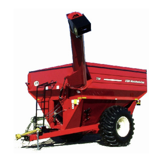
- Page 1 O P E R A T O R ’ S M A N U A L G R A I N C A R T S 750-18 Grain Cart J. & M. Mfg. Co., Inc. P.O. Box 547 Ft. Recovery, OH 45846 Ph: (419) 375-2376 Fax: (419) 375-2708 www.jm-inc.com...
- Page 2 TO THE DEALER: Read manual instructions and safety rules. Make sure all items on the Dealer’s Pre-Delivery and Delivery Check Lists in the Operator’s Manual are completed before releasing equipment to the owner. The dealer must complete the Warranty Registration Card attached to the front inside cover of this manual and return to J. &...
- Page 3 Most Avaliable Phone Number:__________________________________________________________...
-
Page 4: Introduction
PLEASE CUT AND RETURN... -
Page 5: Specifications
750-18 GRAIN CART SPECIFICATIONS DIMENSIONS SPECIFICATIONS 21” Capacity 750 bushels 153” Auger, one vertical 18” diameter 75” Wheels 21x32 or 27x32 168” Hubs 10 bolt 229” Spindles 4 1/2” diameter 151” Weight (approx.) 7,600# 84” 1,000 rpm 136” Tire Size 24.5x32, 12 ply or... -
Page 6: Bolt Torque Chart
GENERAL INFORMATION BOLT TORQUE CHART Always tighten hardware to these values unless a different torque or tightening procedure is listed for a specific application. Fasteners must always be replaced with the same grade as specified in the manual parts list. Always use the proper tool for tightening hardware: SAE for SAE hardware and Metric for metric hard- ware. -
Page 7: Table Of Contents
TABLE OF CONTENTS INTRODUCTION EXPRESS WARRANTY SPECIFICATIONS GENERAL INFORMATION BOLT TORQUE CHART SAFETY RULES SAFETY SIGNS INITIAL OPERATION OPERATION 9-10 ROUTINE MAINTENANCE TROUBLE SHOOTING SERVICE 13-14 STORAGE REMOVING FROM STORAGE PARTS LISTS/DIAGRAMS 15-20 WEIGH SCALE INSTALLATION INSTRUCTIONS 21-23 ROLL TARP INSTALLATION 24-29 AUTO LOG INSTALLATINO SERVICE RECORDS... -
Page 8: Safety Rules
SAFETY RULES ATTENTION! BECOME ALERT! YOUR SAFETY IS INVOLVED! Safety is a primary concern in the design and manufacture of our products. Unfortunately, our efforts to provide safe equipment can be erased by an operator’s single careless act. In addition, hazard control and accident prevention are dependent upon the awareness, concern, judgement, and proper training of personnel involved in the operation, transport, maintenance and storage of equipment. -
Page 9: Safety Signs
750-16 OWNER’S MANUAL SAFETY SIGNS ATTENTION! BECOME ALERT! YOUR SAFETY IS INVOLVED! Replace Immediately If Damaged or Missing! IMPORTANT: Install new safety signs if the old signs are Ref. # Description Part # Req’d destroyed, lost, painted over or cannot be read. When Sign, Danger CDD-101 parts are replaced that have safety signs, make sure... -
Page 10: Initial Operation
INITIAL OPERATION/MAINTENANCE BE CERTAIN THAT ALL POWER IS SHUT OFF BEFORE SERVICING THE GRAIN CART. Before the grain cart is put into service: Have the safety instructions been read and clearly understood by the operator(s) of this machine? Has the gearbox been properly filled with EP-80-90 gearbox lubricant? Have all nuts, bolts, bearings and braces been properly fastened? IMPORTANT: Has the slip clutch on the PTO been serviced? If the slip clutch is left unchecked, damage to the power-take-off and drive shaft may result. - Page 11 Preparing the Grain Cart for Use (see tractor recommendation for grain cart model below): Model 750-16 or 750-18 Grain Cart requires a 130 hp tractor or larger. IMPORTANT: Do NOT pull loaded grain cart on highway. For incidental highway travel, observe the section below.
- Page 12 LOADING AND UNLOADING THE GRAIN CART 1) With the gate indicator in the closed position, fill the tank with grain. 2) With the PTO disengaged, fold discharge auger to upright position. 3) IMPORTANT: After the auger is in the upright position, be sure to start the PTO at a SLOW RATE OF SPEED until the lugs on the upper auger engage the drive dog on the bottom auger (failure to follow this procedure may cause extensive damage to both the drive dog and drive line.) 4) Increase PTO speed and open the inner gate until the pointer is in the half-way position.
-
Page 13: Lubrication Service Schedule
LUBRICATION SERVICE SCHEDULE IMPORTANT: Your Grain Cart has grease fittings at all critical points. These should be serviced before the cart is put into operation. BE CERTAIN THAT ALL POWER IS SHUT OFF BEFORE SERVICING THE GRAIN CART. Hitch: There is a grease fitting located on the pivot shaft of the swivel hitch. PTO &... -
Page 14: Trouble Shooting
TROUBLE SHOOTING MAKE SURE THAT ALL POWER IS SHUT OFF BEFORE SERVICING THE GRAIN CART. MAINTENANCE AND REPAIR SERVICE WORK TO BE PERFORMED BY QUALIFIED SERVICEMEN ONLY. Trouble... Possible Cause ... Possible Remedy ... Auger will not return to down posi- Dirt in restricter Remove restricter fittings from tion or move from stow position... -
Page 15: Service
ADJUSTING THE SLIP CLUTCH After the first hour of operation, the slip-disc clutch should be checked for overheating. After this first check, the slip-disc clutch should be checked weekly or anytime there is excessive slippage of the friction discs. The slip-disc clutch should be checked for moisture, which could cause corrosion on the drive plates. If the grain cart has been idle for an extended period of time, or in wet weather, check to make sure that the friction lining plates are not rusted or corroded together. -
Page 16: Storage
ADJUSTING THE UPPER FLIGHTING MAKE SURE THAT ALL POWER IS SHUT OFF BEFORE ADJUSTING THE FLIGHTING ASSEMBLY. If the upper and lower flightings do not properly separate during the unfolding sequence, the upper flighting may need adjusting. Before making adjustment to upper flighting, check to see if the lugs and drive-dog are locking together (If not, dirt in the restricter or a faulty check valve on the hydraulic cylinder that is used to raise the upper tube may be the cause of the problem. -
Page 17: Repair Parts List And Diagrams
REPAIR PARTS LIST AND DIAGRAMS When performing maintenance work, wear sturdy, rough-soled work shoes and protective equipment for eyes, hair, hands, hearing and head. Follow Operator’s Manual instructions to ensure safe and proper maintenance and repair. Your local, authorized dealer can supply genuine replacement parts. Substitute parts may not meet original equipment specifications and may be dangerous. -
Page 18: Power Take-Off Shaft
POWER TAKE-OFF SHAFT Part # Description 28428 Complete Collar Yoke C15 18130 Cross Journal Set 18133 Outer Yoke 00243 Roll Pin for Outer Tube 18210 Bush with Grease Nipple 30710 Complete Outer Tube 90010 Inner Tube 00271 Roll Pin for Inner Tube 18134 Inner Yoke 84033 Complete Slip Clutch 19121 Retain Collar for Outer Tube... - Page 19 DRIVE LINE ASSEMBLY Part # Description 252288 U-Joint (drive shaft to gearbox) UCF-20928 1 3/4” Flange Bearing, 4 hole 38112 3/8” x 1 1/2” Half Moon Key SS-3812 3/8” x 1/2” Set Screw SS-1212 1/2”-20 x 1/2” Set Screw DS-134101 Drive Shaft 1 3/4”...
-
Page 20: Hydraulic Cylinder
HYDRAULIC CYLINDER Part # Description JD25024 2 1/2” x 24” Hyd. Cylinder JD469 Seal Kit for 2 1/2” x 24” Hydraulic Cylinder ICR4 1” x 4” Pin with Hair Pin 38SE90 3/8” Street Elbow 90 5602-6-6 3/8” Street Tee PC-37 Pilot Check Valve BJW-114 Ball Joint Weldment with... - Page 21 HYDRAULIC DRIVEN FLOW CONTROL SPOUT Part # Description FSH-18 Flow Control Spout Housing HP-18 Hinge BP-18 Baffle Plate HC-FCS Hyd. Cylinder with clevis end and 1/2”-20 regular nut SKHC-FCS Seal Kit for Hydraulic Cylinder HH-1428 1/4” x 28’ Hydraulic Hose PQC-1 Pioneer Quick Coupler SR-14...
- Page 22 GRAIN CART LIGHT KIT Part # Description 8WH-7PC Main Wiring Harness with 7-Prong Connector End LE-1B Light Enhancer (108060) WH-1 Wiring Harness (Rear Half) EL-A1 Extendable Amber Light Assembly (Left/Right) RL-R1L Rear Red Light, Left RL-R1R Rear Red Light, Right MS-1 Mercury Switch FLW-1...
-
Page 23: Spindle Assembly
Installation of Scale Kit (Single Wheel Applications) For Models 525-14W, 620-14, 750-14, 750-16, 750-18, 875-16 and 875-18 HITCH ASSEMBLY HITCH PARTS Remove the 2 1/2” x 13 1/4” shaft from the swivel Weigh Bar hitch by unbolting the 1” x 5 1/2” Grade 5 bolt and Weldment locknut that attaches the swivel hitch and the 1”... -
Page 24: Mounting The Junction Box
Installation of Scale Kit (Single Wheel Application) For Models 525-14W, 620-14, 750-14, 750-16, 750-18, 875-16 and 875-18 Use Junction Box as a template to drill holes on MOUNTING THE JUNCTION BOX inside face of front grain cart leg. (Digi-Star Scale Systems Only) -
Page 25: Connecting The Power Cord
Installation of Scale Kit (Single Wheel Application) For Models 525-14W, 620-14, 750-14, 750-16, 750-18, 875-16 and 875-18 CONNECTING THE POWER CORD To connect the Power Cord to the Indicator Box, attach screw plug end of PARTS LIST (Weigh-Tronix or Digi-Star Scale Systems) -
Page 26: Roll Tarp Installation
Grain Cart Roll Tarp Parts List and Set Up Instructions Rear View of Grain Cart PARTS LIST Part # Description Part # Description SO-2 Stand-Off TL-192 Tightening Lip x 192” (875) CUJ-1N Crank with Splined U-joint (525) TL-264 Tightening Lip x 264” CUJ-1NL Crank with Splined U-joint (620 (1000 thru 1151) (2 pcs L/R) - Page 27 Grain Cart Roll Tarp Parts List and Set Up Instructions Part # Description 316C-150 3/16” Cable (525) 316C-164 3/16” Cable (620) 316C-174 3/16” Cable (750) 316C-198 3/16” Cable (875) 316C-1050 3/16” Cable (1000 thru 1151) 270”L Exploded View of Spring Return 316C-240 3/16”...
-
Page 28: Setup Instructions
Roll Tarps for Grain Carts SET-UP INSTRUCTIONS Installing the Lock Panel (Drip Edge) Center the lock panel from the front to the rear of Lock panel placed on Opposite the cart on the off auger side of the cart. Make Auger Side. - Page 29 Roll Tarps for Grain Carts SET-UP INSTRUCTIONS (Continued) Installing the Tarp Bows Lay all three bows in the cart with the View of Tarp Bow mount brack bolted ends on the sideboareds. Then install two over lip lock. 1/4”-20 x 3/4” serrated flange hex bolts and two 1/4”-20 serrated flange hex nuts on each end of all bows.
- Page 30 Roll Tarps for Grain Carts SET-UP INSTRUCTIONS (Continued) Tarp Stand-Offs Installing the Tarp Stand-Offs Install each tarp standoff at each end of the grain cart wall on the off auger side with two 1/4” x 1 1/2 self tapping bolts. Place it about 2”...
- Page 31 Roll Tarps for Grain Carts SET-UP INSTRUCTIONS (Continued) Attaching the Canvas Tarp to the Roll Pipe On the opposite side of the canvas tarp, slide the 1” schedule roll pipe into the remainng sleeve on the canvas tarp with the spline end towards Front Spring Return on the rear of the cart.
-
Page 32: Auto Log Installatino
DIGI-STAR Autolog for Grain Carts SET-UP INSTRUCTIONS To complete the installation of the Digi-star Autolog system on a grain cart drive shaft: First remove the drive shaft cover guard located on the backside of the middle bearing on the drive shaft (detail 1). The drive shaft cover tube (detail 5) can now be cut back six inches from the end closest to the front of the cart. -
Page 33: Service / Maintenance Record
SERVICE / MAINTENANCE RECORD DATE DESCRIPTION NOTES...
Need help?
Do you have a question about the 750-18 and is the answer not in the manual?
Questions and answers