Advertisement
Quick Links
Advertisement

Related Manuals for NCR 7364-K015


Summary of Contents for NCR 7364-K015
- Page 1 Kit Instructions Second Display Mount 7364-K015 Issue A...
- Page 2 NCR, therefore, reserves the right to change specifications without prior notice. All features, functions, and operations described herein may not be marketed by NCR in all parts of the world. In some instances, photographs are of equipment prototypes. Therefore, before using this document, consult with your NCR representative or NCR office for information that is applicable and current.
-
Page 3: Revision Record
Revision Record Issue Date Remarks Dec 2018 First Issue... -
Page 4: Kit Contents
Second Display Mount This publication provides procedures for installing a Second Display Mount on an NCR FastLane SelfServ™ Checkout (7364) R6-G unit. Kit Contents Part Number Description 497–0522536 7364–K015 Second Display Mount 795–0267101 5910 Display Mount 497–0512559 Display Port Cable 497–0521788... -
Page 5: Installation Procedure
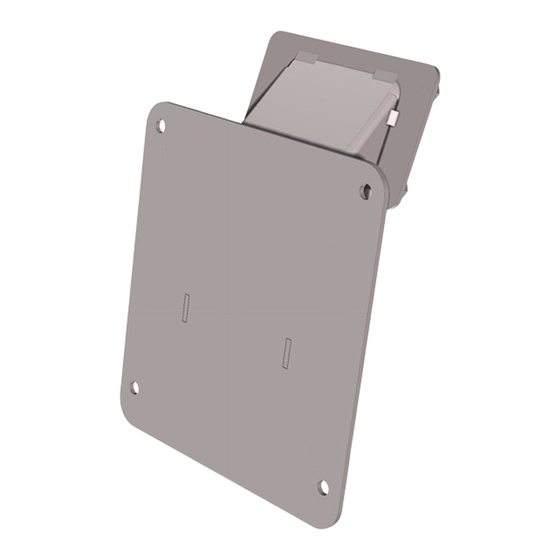
7364-K015 Second Display Mount Installation Procedure Installing the Second Display Mount on an R6-G unit involves the following procedures: A. Installing the Second Display Mount on the Second Display unit. For more information, refer to Installing the Second Display Mount on the facing page. - Page 6 7364-K015 Second Display Mount Installing the Second Display Mount To install the Second Display Mount on the Second Display unit, follow these steps: 1. Place the Second Display on a flat surface with the back facing up as shown in the image below.
- Page 7 7364-K015 Second Display Mount 3. Install and secure the Second Display Mount on the back of the Second Display unit using four M4 Screws. 4. Route the cables through the Second Display Mount hole as shown in the image below.
- Page 8 7364-K015 Second Display Mount Installing the Second Display Assembly To install the Second Display Assembly on the Tower Cabinet, follow these steps: 1. Install the Second Display Mount on the Second Display unit. For more information, refer to Installing the Second Display Mount on page 3.
- Page 9 7364-K015 Second Display Mount 4. Insert the Second Display cables through the Tower Cabinet hole as shown in the image below. 5. Install and secure the Second Display Assembly on the Tower Cabinet using four M4 nuts.
- Page 10 7364-K015 Second Display Mount 6. Route the DB9 / USB Split Cable through cable loops and then connect to the Kiosk I/O Board as shown in the image below.
- Page 11 7364-K015 Second Display Mount 7. Route the Display Port Cable through cable loops and then connect to the Terminal Display Port. Ensure that cables are secured with cable ties as shown in the image below.
Need help?
Do you have a question about the 7364-K015 and is the answer not in the manual?
Questions and answers