Tektronix TLA7000 Series Installation Manual
Logic analyzers
Hide thumbs
Also See for TLA7000 Series:
- Installation manual (121 pages) ,
- Technical reference manual (72 pages) ,
- Instructions manual (11 pages)

Related Manuals for Tektronix TLA7000 Series


Summary of Contents for Tektronix TLA7000 Series
- Page 1 (217) 352-9330 | Click HERE Find the Tektronix TLA7016 at our website:...
- Page 2 TLA7000 Series Logic Analyzers Installation Manual www.tektronix.com *P077174705* 077-1747-05...
- Page 3 Copyright © Tektronix. All rights reserved. Licensed software products are owned by Tektronix or its subsidiaries or suppliers, and are protected by national copyright laws and international treaty provisions. Tektronix products are covered by U.S. and foreign patents, issued and pending. Information in this publication supersedes that in all previously published material.
- Page 4 Tektronix, with shipping charges prepaid. Tektronix shall pay for the return of the product to Customer if the shipment is to a location within the country in which the Tektronix service center is located. Customer shall be responsible for paying all shipping charges, duties, taxes, and any other charges for products returned to any other locations.
- Page 5 In order to obtain service under this warranty, Customer must notify Tektronix of the defect before the expiration of the warranty period. If Tektronix is unable to provide a replacement that is free from defects in materials and workmanship within a reasonable time thereafter, Customer may terminate the license for this software product and return this software product and any associated materials for credit or refund.
-
Page 6: Table Of Contents
Connect to the Mainframe ................Changing the TLA7016 Factory Network Settings ..........Networking Tips & Troubleshooting ............... Connecting to the Mainframe................Multi-mainframe Systems................Adding Location Information for the Connection Dialog Box ........TLA7012 Server Control................TLA7000 Series Logic Analyzers Installation Manual... - Page 7 Installing Modules in the Portable Mainframe............Installing Modules in the Benchtop Mainframe ............Covering Empty Slots ................... Connecting Accessories..................Connecting Accessories to the TLA7000 Series ............. Additional Accessory Connection Information............Connecting Probes .................... Connecting Probes to the Logic Analyzer Module...........
- Page 8 In Case of Problems ..................Diagnostics ....................Software Problems ..................Hardware Problems ..................Repacking for Shipment ..................Appendix C: Accessories and Options ................Accessories ....................Options....................... Field Kit Options.................... Appendix D: TLA7000 Network Installation Site Survey ..........Index TLA7000 Series Logic Analyzers Installation Manual...
- Page 9 Figure 31: Make changes to the TLA network settings ............Figure 32: Example of the ping command..............Figure 33: Example of the tracert command ..............Figure 34: TLA Network Search dialog box ..............Figure 35: TLA Connection dialog box, search results ............TLA7000 Series Logic Analyzers Installation Manual...
- Page 10 Figure 64: Restore Factory Default settings results ............Figure 65: Portable mainframe front panel ..............Figure 66: TLA7000 Series external connectors............... Figure 67: Flash programming pins ................Figure 68: Maximum power allowed to modules at various line voltages for TLA7016 mainframes serial number B020000 and higher ................
- Page 11 Table 16: Optional accessories, Deskew fixture ............. Table 17: Instrument options ................... Table 18: Power cords ..................Table 19: Options for TLA7AC4 modules ..............Table 20: Options for TLA7Bxx modules ..............Table 21: Options for TLA7BC4 modules..............TLA7000 Series Logic Analyzers Installation Manual...
-
Page 12: General Safety Summary
Avoid exposed circuitry. Do not touch exposed connections and components when power is present. Use proper AC adapter. Use only the AC adapter specified for this product. Use proper fuse. Use only the fuse type and rating specified for this product. TLA7000 Series Logic Analyzers Installation Manual... - Page 13 DANGER indicates an injury hazard immediately accessible as you read the marking. WARNING indicates an injury hazard not immediately accessible as you read the marking. CAUTION indicates a hazard to property including the product. The following symbol(s) may appear on the product: viii TLA7000 Series Logic Analyzers Installation Manual...
-
Page 14: Service Safety Summary
Use Care When Servicing With Power On. Dangerous voltages or currents may exist in this product. Disconnect power, remove battery (if applicable), and disconnect test leads before removing protective panels, soldering, or replacing components. To avoid electric shock, do not touch exposed connections. TLA7000 Series Logic Analyzers Installation Manual... -
Page 15: Preface
Be sure to follow all warnings, cautions, and notes in this manual. TLA7000 Series Logic Analyzers The TLA7000 Series Logic Analyzers consist of a 2-module portable mainframe (TLA7012) and a 6-module benchtop mainframe (TLA7016). The TL708EX TekLink 8-Port Hub and a local area network (LAN) gigabit (Gb) switch expand the system and connect it to your network. -
Page 16: Figure I: Tla7012 Portable Mainframe
Figure i: TLA7012 Portable Mainframe Several logic analyzer modules are available in various combinations of channel width, state speed, and memory depth. All of the logic analyzer modules provide simultaneous state and timing measurements through a single probe. TLA7000 Series Logic Analyzers Installation Manual... -
Page 17: Documentation
The following table lists related documentation available for your logic analyzer. The documentation is available on the TLA Documentation CD and on the Tektronix Web site (www.tektronix.com/manuals). For documentation not specified in the table, contact your local Tektronix representative. Related Documentation... - Page 18 Verification Procedures performance verification procedures TPI.NET Documentation Detailed information for controlling the logic analyzer using .NET Field upgrade kits Upgrade information for your logic analyzer Optional Service Manuals Self-service documentation for modules and mainframes TLA7000 Series Logic Analyzers Installation Manual xiii...
- Page 19 Preface TLA7000 Series Logic Analyzers Installation Manual...
-
Page 20: Basic Installation
Basic Installation This chapter describes all of the steps needed to install your Tektronix logic analyzer and its related accessories. It is written from the perspective that you purchased most of the items uninstalled and you intend to install all of the pieces. -
Page 21: Site Considerations
Basic Installation Site Considerations Read this section before installing the logic analyzer. This section describes operating considerations and power requirements for your logic analyzer. The environmental considerations apply to all TLA7000 series products. Table 1: Environmental considerations Feature Description Temperature Operating +5 °C to +45 °C... -
Page 22: Support Hardware Site Considerations
Power 300 W maximum Consumption TL708EX Voltage 90 VAC to 250 VAC at 45 Hz to 66 Hz range and frequency Input 2 A maximum at 100 VAC Current Power 200 W maximum Consumption TLA7000 Series Logic Analyzers Installation Manual... -
Page 23: Installing The Bracket Kit
6. Using the 10-32, P2 Pozidriv screws preinstalled on the brackets, fasten the components to the brackets. Figure 1: Bracket kit for the TL708EX Hub, TLA7PC1 controller and GbE switch installed on a TLA7016 TLA7000 Series Logic Analyzers Installation Manual... -
Page 24: Chassis Ground Connections
The first time you start up your instrument you should decide if you are going to connect to a network. Plan to connect to a network if you want to: Considerations Share files over the network Print to a shared printer Control the instrument remotely TLA7000 Series Logic Analyzers Installation Manual... -
Page 25: Connecting To A Network
Basic Installation The TLA7000 series mainframes can be set up in several configurations, depending on the number of mainframes you want to use and whether you want to connect to a network. The following table shows the network configurations that can be set up. -
Page 26: Network Security
TLA7016 mainframes on your network. To eliminate this long search time, Tektronix recommends that you include a hosts file on your PC under <Windows folder>\system32\drivers\etc directory. (An example of the contents of this file is shown below.) 120.0.0.1... -
Page 27: First Time Network Setup
IP address, either DHCP (default) or static Domain Name Service (DNS) Other network information from your network administrator The Teklink/TLA7000 series mainframes require the following services: DHCP Firewall Blocking Network Ports. If you are having problems with any of the following applications, your firewall may be blocking communications using... -
Page 28: Table 6: First Time Network Setup
Network Switch. The 16 port network switch controls the data flow between the controller and mainframes. Connect the GbE switch between the logic analyzer mainframe and the TLA7PC1 Controller or an external PC (loaded with the TLA application). (See Figure 3.) TLA7000 Series Logic Analyzers Installation Manual... -
Page 29: Preset Ip Addresses
A preset list of recommended IP addresses is programmed into the benchtop mainframe. (See Table 7.) You can also set a specific address. (See page 36, Changing the TLA7016 Factory Network Settings.) TLA7000 Series Logic Analyzers Installation Manual... -
Page 30: Figure 5: Setting The Ip Address
DHCP-capable router – – – Factory default Return to factory settings (Use DHCP and restore default Host Name to TLA7016_<Mainframe S/N>) – – – No change Retain current IP address and Host Name TLA7000 Series Logic Analyzers Installation Manual... -
Page 31: Instrument Installations
TLA7016 benchtop on a private LAN TLA7016 benchtop on a corporate LAN NOTE. You must have TLA Application software Version 5.6 or higher installed on the controller PC. (See page 32, Installing the TLA Application Software on a PC.) TLA7000 Series Logic Analyzers Installation Manual... -
Page 32: Stand-Alone Installation (Portable Mainframe)
3. Start the TLA application on the controller. 4. Find and connect to the TLA mainframe through software control. 5. Repeat for all mainframes in the test system. 6. Operate the TLA from the controller or remote computer. TLA7000 Series Logic Analyzers Installation Manual... -
Page 33: Stand-Alone Installation (Benchtop Mainframe)
1. From the Control Panel on the controller, select Network Connections. 2. Right-click the Local Area Connection icon that corresponds to your local LAN card and select Properties from the menu. The Properties dialog box appears. (See Figure 8.) TLA7000 Series Logic Analyzers Installation Manual... -
Page 34: Figure 8: Lan Connection Dialog Box
Basic Installation Figure 8: LAN Connection dialog box 3. Scroll down the list and select Internet Protocol (TCP/IP); and then click Properties. The Internet Protocol (TCP/IP) Properties dialog appears. (See Figure 9.) TLA7000 Series Logic Analyzers Installation Manual... -
Page 35: Figure 9: Ip Properties Dialog Box
Figure 5 on page 11.) The front-panel display cycles every 2-3 seconds to the next preset address. (See Table 7 on page 11.) 8. Start the TLA application by double-clicking the TLA Application icon on the controller. The TLA Connection dialog box appears. (See Figure 10.) TLA7000 Series Logic Analyzers Installation Manual... -
Page 36: Figure 10: Tla Connection Dialog Box
(Search icon) to open the TLA Network Search dialog box. (See Figure 11.) Figure 11: TLA Network Search dialog box b. Verify that Locate TLA systems on local subnet is checked. c. Verify that Include these hostnames or IP in search is checked. TLA7000 Series Logic Analyzers Installation Manual... -
Page 37: Private Lan (Benchtop Mainframe)
2. Connect the peripheral components that you plan to use. (See page 48, Connecting Accessories.) 3. Connect the power cord to the router and power on the router. 4. Connect the power cords and power on the controller and mainframe. TLA7000 Series Logic Analyzers Installation Manual... -
Page 38: Figure 13: Lan Connection Dialog Box
LAN card and select Properties. The Properties dialog box appears. (See Figure 13.) Figure 13: LAN Connection dialog box 7. Scroll down the list and select Internet Protocol (TCP/IP), and then click Properties. The Internet Protocol (TCP/IP) Properties dialog box appears. (See Figure 14.) TLA7000 Series Logic Analyzers Installation Manual... -
Page 39: Figure 14: Ip Properties Dialog Box
8. Select Obtain an IP address automatically. 9. Click OK and close the dialog boxes. 10. Start the TLA application by double-clicking the TLA Application icon on the controller. The TLA Connection dialog box appears. (See Figure 15.) TLA7000 Series Logic Analyzers Installation Manual... -
Page 40: Figure 15: Tla Connection Dialog Box
(See Figure 16.) Figure 16: TLA Network Search dialog box b. Verify that Locate TLA systems on local subnet is checked. c. Verify that Include these host names or IP in search is checked. TLA7000 Series Logic Analyzers Installation Manual... -
Page 41: Corporate Lan (Benchtop Mainframe)
Figure 17: Benchtop mainframe corporate LAN setup (up to six modules) NOTE. Tektronix recommends that you conduct a network installation site survey with the help of your network administrator to determine the networking requirements. A recommended site survey form is available at the end of this document. -
Page 42: Figure 18: Lan Connection Dialog Box
LAN card and select Properties. The Properties dialog box appears. (See Figure 18.) Figure 18: LAN Connection dialog box 5. Scroll down the list and select Internet Protocol (TCP/IP), and then click Properties. The Internet Protocol (TCP/IP) Properties dialog appears. (See Figure 19.) TLA7000 Series Logic Analyzers Installation Manual... -
Page 43: Figure 19: Ip Properties Dialog Box
6. Select Obtain an IP address automatically. 7. Click OK and close the dialog boxes. 8. Start the TLA application by double-clicking the TLA Application icon on the controller. The TLA Connection dialog box appears. (See Figure 20.) TLA7000 Series Logic Analyzers Installation Manual... -
Page 44: Figure 20: Tla Connection Dialog Box
(See Figure 21.) Figure 21: TLA Network Search dialog box b. Verify that Locate TLA systems on local subnet is checked. c. Verify that Include these host names or IP in search is checked. TLA7000 Series Logic Analyzers Installation Manual... - Page 45 (See page 39, Multi-mainframe Systems.) 11. Select the mainframe and click the Connect button. The application opens the controller display. 12. Refer to the TLA Quick Start User Manual and to the online help for operating information. TLA7000 Series Logic Analyzers Installation Manual...
-
Page 46: Setting Up Multiple Mainframe Configurations
Setting up Multiple Mainframe Configurations You can configure your system to link up to eight mainframes together, for a total of up to 48 modules. The TLA7000 Series mainframes use the TekLink system to connect multiple-mainframe systems together. The TekLink system is described here in the two Expanded System sections. -
Page 47: Figure 23: Two Instrument Configuration
TekLink cable; it is not available if you are using the TL708EX TekLink 8-Port Hub. Figure 23: Two instrument configuration 6. Refer to your TLA Quick Start User Manual and to the online help for operating information. TLA7000 Series Logic Analyzers Installation Manual... -
Page 48: Expanded System (Three To Eight Mainframes)
TekLink 8-Port Hub and the TekLink cables. (See Figure 24.) The hub can to Eight Mainframes) accommodate up to eight mainframes (48 modules total). Figure 24: Expanded benchtop system with TL708EX Hub (up to 48 modules) TLA7000 Series Logic Analyzers Installation Manual... -
Page 49: Figure 25: Tl708Ex Hub And Teklink Cable
TL708EX TekLink 8-Port Hub. The TL708EX Hub is housed in a standard 19 inch rackmount frame. (See Figure 25.) The hub allows you to expand your system to accommodate up to seven additional TLA7000 Series mainframes, configured as expansion mainframes (48 modules total). -
Page 50: Figure 26: Tla Network Search Dialog Box
11. Click the Configuration icon and verify that the system is configured as you intended. Note that in systems with three or less benchtop mainframes, physically merged modules are not automatically established as a merged set until you merge them through software. (See Figure 27.) TLA7000 Series Logic Analyzers Installation Manual... -
Page 51: Installing The Tla Application Software On A Pc
Follow the on-screen instructions to remove the software, answering "Yes" to any prompts. Do not cancel the uninstall program, as this may cause undesirable effects. Restart the PC when prompted. TLA7000 Series Logic Analyzers Installation Manual... -
Page 52: Controlling The Logic Analyzer Remotely
PC. (The benchtop mainframe Mainframe is factory-set to be controlled remotely, so this step is not required.) If you are setting up a benchtop mainframe, go to Connect to the Mainframe. TLA7000 Series Logic Analyzers Installation Manual... -
Page 53: Connect To The Mainframe
Verify that Include these host names or IP in search is checked. d. If you know the host name or IP address of the TLA, add it to the list of hosts to search. TLA7000 Series Logic Analyzers Installation Manual... -
Page 54: Figure 29: Tla Network Search Dialog Box
The application opens on the remote instrument and displays on your PC. Note that the IP Address identification is shown in the title bar. This confirms that you have connected to the correct device. TLA7000 Series Logic Analyzers Installation Manual... -
Page 55: Changing The Tla7016 Factory Network Settings
3. Click the TLA Configuration icon. The TLA Configuration dialog box opens. (See Figure 30.) Figure 30: TLA Configuration dialog box 4. Select the mainframe that you want to change and click Network Properties. The Network Properties dialog box appears. (See Figure 31.) TLA7000 Series Logic Analyzers Installation Manual... -
Page 56: Figure 31: Make Changes To The Tla Network Settings
5. Make the desired changes and click OK. For example, to change the mainframe to a static address, click the Use the following Address and enter the IP address information in the appropriate fields. TLA7000 Series Logic Analyzers Installation Manual... -
Page 57: Networking Tips & Troubleshooting
firewall is enabled. 6. Use the tracert command to display the path of the data packets from the controller PC to the mainframe. (See Figure 33.) TLA7000 Series Logic Analyzers Installation Manual... -
Page 58: Multi-Mainframe Systems
To minimize this delay, you can delete the mainframes from the system by doing the following: TLA7000 Series Logic Analyzers Installation Manual... -
Page 59: Figure 34: Tla Network Search Dialog Box
Click Search to search for the remaining instruments in the list. When the search is complete, a list of found, powered-on TLA systems is displayed. (See Figure 35.) The list also shows the current status, model, and location of the instruments. TLA7000 Series Logic Analyzers Installation Manual... -
Page 60: Adding Location Information For The Connection Dialog Box
System Properties dialog box: Information for the Connection Dialog Box 1. Connect to your logic analyzer. 2. From the System menu, select System Properties. The System Properties dialog box appears. (See Figure 36.) TLA7000 Series Logic Analyzers Installation Manual... -
Page 61: Tla7012 Server Control
To change the server control so that the instrument starts the server when you turn on the instrument, complete the following steps: 1. Right-click the (TLA Server) icon in the taskbar and select Server Properties. 2. Check Launch TLA Server Control during login. (See Figure 37.) TLA7000 Series Logic Analyzers Installation Manual... - Page 62 Basic Installation Figure 37: TLA Server Properties dialog box 3. Click OK. If you experience other network connection problems, call the Technical Support group. See Contacting Tektronix in the front of this manual. TLA7000 Series Logic Analyzers Installation Manual...
-
Page 63: Installing Modules
Basic Installation Installing Modules TLA700 Modules are fully compatible with the TLA7000 Series mainframes. This section describes how to install TLA700 modules in your TLA7000 mainframe. CAUTION. To avoid damaging the instrument, do not install or remove any modules while the instrument is powered on. Always power down the instrument before installing or removing modules. -
Page 64: Installing Modules In The Portable Mainframe
3-4. When installing two logic analyzer modules with different amounts of memory, install the module with the larger memory in slots 3-4. Install the module with the lower memory in slots 1-2. TLA7000 Series Logic Analyzers Installation Manual... -
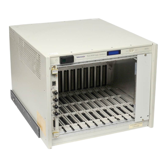
Page 65: Installing Modules In The Benchtop Mainframe
Use a screwdriver to tighten the retaining screws to 2.5 in-lbs after seating the modules in place. (See Figure 39 on page 47.) TLA7000 Series Logic Analyzers Installation Manual... -
Page 66: Covering Empty Slots
Portable Mainframe. (See Figure 40.) Install the blank slot-panels on the benchtop mainframe. (See Figure 41.) Install the blank-slot panel covers before any modules. Use only Tektronix TLA covers; otherwise the mainframe may not meet EMC and cooling requirements. -
Page 67: Connecting Accessories
Connect the accessories to the Portable Mainframe. (See Figure 42.) If you have a benchtop mainframe, connect the accessories to external PC; connect other cables the TLA7000 Series and connectors to the benchtop mainframe. (See Figure 43 on page 50.) TLA7000 Series Logic Analyzers Installation Manual... - Page 68 Basic Installation Figure 42: TLA7012 accessories connections TLA7000 Series Logic Analyzers Installation Manual...
-
Page 69: Additional Accessory Connection Information
LAN switch using your PC (loaded with the TLA application software), or the dedicated PC controller (TLA7PC1). Printer The instruments send printer information to the USB ports. Use any of the four USB ports for your printer. TLA7000 Series Logic Analyzers Installation Manual... -
Page 70: Connecting Probes
Connecting Probes to the Connect the logic analyzer probes to the logic analyzer modules. Logic Analyzer Module Figure 44: Connecting the P69xx logic analyzer probes to the TLA7Axx or TLA7Bxx or logic analyzer module TLA7000 Series Logic Analyzers Installation Manual... -
Page 71: First Time Operation
2. If you have an external monitor, connect the power cord and turn on the monitor. 3. Press the On/Standby switch to turn on the mainframe. (See Figure 46.) 4. Wait for the mainframe to complete the power-on self tests. TLA7000 Series Logic Analyzers Installation Manual... -
Page 72: Turning On Expansion Mainframes
This procedure creates a set of restore discs for the Microsoft Windows operating system. After restoring the operating system, use the TLA Application disc to reinstall the TLA application software. (See page 85, Reinstalling the TLA Application Software.) TLA7000 Series Logic Analyzers Installation Manual... -
Page 73: Performing The Incoming Inspection
You can also verify more detailed functionality by running the self-calibration and extended diagnostics. NOTE. Allow the mainframe and modules to warm up for 30 minutes before running the self-calibration. TLA7000 Series Logic Analyzers Installation Manual... -
Page 74: Checking The Logic Analyzer Probes (Optional)
To check the mainframe diagnostics not covered by the TLA Application software, run the TLA7000 Mainframe Diagnostics located under the Windows Start menu Mainframe (Optional) (Start/Programs/Tektronix Logic Analyzer/TLA Mainframe Diagnostics). Exit the TLA Application before running the external diagnostics. Backing Up User Files Back up your user files on a regular basis. -
Page 75: Connecting Probes To The Target System
The logic analyzer connects to the target system through the probes. The logic analyzer probes allow you to connect to the target system in several different ways. For probe-specific connection details, refer to the appropriate probe instruction manual or browse through the Tektronix Web site. TLA7000 Series Logic Analyzers Installation Manual... -
Page 76: Merging Modules
In systems with three or fewer benchtop mainframes, physically merged modules are not automatically established as a merged set until you merge them through software. TLA7000 Series Logic Analyzers Installation Manual... -
Page 77: Merge Procedure
If you have a two module set, the master module is located in the lower-numbered slot, and the slave module is in the higher-numbered slot. Figure 48: Location of modules in a merged system TLA7000 Series Logic Analyzers Installation Manual... -
Page 78: Merging Tla7Axx, Tla7Bxx, Or Tla7Nax Modules
Figure 49: Removing the merger connector assembly from the module 3. Gently lift the merge connector out of the slot and place it in the extended position such that the screw holes line up over the two standoff posts. TLA7000 Series Logic Analyzers Installation Manual... - Page 79 10. Align the tops and bottoms of the modules with the slots in the mainframe. (See Figure 51 on page 61.) You may need the help of another person if your merged module set contains more than two modules. TLA7000 Series Logic Analyzers Installation Manual...
- Page 80 Merging Modules Figure 51: Installing the merged module set in the mainframe TLA7000 Series Logic Analyzers Installation Manual...
-
Page 81: Unmerging Tla7Axx, Tla7Axx, Or Tla7Nax Modules
9. Install the two Torx T-10 screws onto the assembly and tighten the screws to 4 in-lbs. 10. Repeat steps 7 through 9 for the other modules. You can now reinstall the modules in the mainframe as needed. TLA7000 Series Logic Analyzers Installation Manual... -
Page 82: Merging Tla7Lx/Mx/Nx/Px/Qx Modules
6. Remove the screws holding the merge cable bracket to the cover. 7. Remove the top part of the cable bracket and set it aside. 8. Remove the module cover and locate the merge cable. TLA7000 Series Logic Analyzers Installation Manual... - Page 83 9. Replace the cover while feeding the merge cable through the hole in the cover. (See Figure 53.) NOTE. Do not twist the cable while feeding it through the hole. If the cable is twisted, the modules will not merge correctly. TLA7000 Series Logic Analyzers Installation Manual...
- Page 84 14. Push forward on the cover so the tab on the front edge of the cover inserts into the rear of the front subpanel. Make sure that the cover is fully seated (no gaps) against the front and rear chassis flanges. TLA7000 Series Logic Analyzers Installation Manual...
- Page 85 19. Check and tighten all screws. 20. Place the master module adjacent to the slave module so that the two guide pins from the slave module line up with the guide pin holes in the master module. TLA7000 Series Logic Analyzers Installation Manual...
-
Page 86: Three-Way Merge Procedure
2 is to the left of the master module. CAUTION. Static discharge can damage any semiconductor component in the logic analyzer module. Discharge the static voltage from your body by wearing a grounded antistatic wrist strap while performing the merge procedure. TLA7000 Series Logic Analyzers Installation Manual... -
Page 87: Storing The Merge Cable
Figure 54 on page 66.) 7. While holding the cover in place, install the screws nearest the front of the module to secure the cover to the chassis. 8. Install the screws near the front of the module. TLA7000 Series Logic Analyzers Installation Manual... - Page 88 11. Install the merge cable bracket so that the guide pins point into the module. 12. Install and tighten the screws on the merge cable bracket. 13. Verify that you have installed and tightened all screws on the module. TLA7000 Series Logic Analyzers Installation Manual...
-
Page 89: Tla7Bxx Deskew Procedures
TLA7Bxx Deskew Procedures TLA7Bxx Deskew Procedures Tektronix recommends that you perform the deskew procedures to provide enhanced performance for high-speed applications using the TLA7Bxx Logic Analyzer modules and probes. The procedures use the TLACAL software with a deskew fixture to adjust the timing of probes to the logic analyzer module. -
Page 90: Prerequisites
If necessary, refer to the TLA Release Notes for software version information. If the software versions do not match, you must remove the old TLACAL software and install the correct version. Click the About TLACAL button in the TLACAL startup window for firmware version information. TLA7000 Series Logic Analyzers Installation Manual... -
Page 91: Deskew Procedure
TLA7Bxx Deskew Procedures Complete the following steps to install the TLACAL software: 1. Close all open applications. 2. Insert Disc 1 of the Tektronix Logic Analyzer Family application software CD in the disc drive. 3. On the desktop select Start → Run.. - Page 92 5. Click the Adjustment button to start the software. The Adjustment procedure dialog box appears. (See Figure 59.) Figure 59: Adjustment procedure dialog box with Deskew selected 6. Verify that Deskew is selected at the top of the dialog box. TLA7000 Series Logic Analyzers Installation Manual...
- Page 93 (See Figure 60.) Figure 60: Example of adjustment results NOTE. If any failures occur, check your probe or deskew fixture connections and reseat them, if necessary. Then click the Back button to restart the test. TLA7000 Series Logic Analyzers Installation Manual...
- Page 94 Next button until you see the probe section that you want. Any probe sections that you skip will display a FAIL status. The FAIL status on other probe sections will not affect the current probe section. TLA7000 Series Logic Analyzers Installation Manual...
- Page 95 3. Select Merged Deskew in the dialog box. (See Figure 61.) 4. Click the Next button and follow the on-screen instructions to complete the Merge Deskew procedure. Figure 61: Adjustment procedure dialog box with Merged Deskew selected TLA7000 Series Logic Analyzers Installation Manual...
- Page 96 1. In the Adjustment procedure dialog box, select Deskew and Merged Deskew. (See Figure 62.) Figure 62: Adjustment procedure dialog box with Deskew and Merged Deskew selected 2. Click the Next button and note the instructions in the dialog box. (See Figure 63.) TLA7000 Series Logic Analyzers Installation Manual...
- Page 97 Figure 63: Deskew procedure: Restore Factory Default instructions 3. If you are sure that you want to run the procedure, click the Next button. The results of the procedure are displayed. (See Figure 64.) TLA7000 Series Logic Analyzers Installation Manual...
- Page 98 TLA7Bxx Deskew Procedures Figure 64: Restore Factory Default settings results 4. Click the Finish button to finish the procedure and return to the startup window. TLA7000 Series Logic Analyzers Installation Manual...
- Page 99 TLA7Bxx Deskew Procedures TLA7000 Series Logic Analyzers Installation Manual...
-
Page 100: Product Overview
External Signal In and External Signal Out, used to receive or send a signal from/to an external source TekLink, used to coordinate trigger signals, input/output signals, and time references between mainframes Accessory connections, such as USB, LAN, and audio/video outputs TLA7000 Series Logic Analyzers Installation Manual... -
Page 101: Connecting An External Display
To enable Simulscan mode, or to enable/disable external monitors or make other display changes, right click on your desktop and select Properties > Graphics > Intel Graphics Technology. Figure 66: TLA7000 Series external connectors TLA7000 Series Logic Analyzers Installation Manual... -
Page 102: Restoring And Reinstalling Software
TLA application software and operating system. If you want to upgrade to a newer TLA application software version, contact your local Tektronix representative. This section also provides information on installing related logic analyzer software on a PC for remote operation or for offline applications. - Page 103 7. Click Next and then configure your regional settings, as needed. 8. Click Next. The instrument will apply the settings and then restart. 9. After the instrument restarts, reinstall the TLA Application software. (See page 85, Reinstalling the TLA Application Software.) TLA7000 Series Logic Analyzers Installation Manual...
-
Page 104: Change The Bios Settings
Windows Start menu to display the Run dialog box. Enter D:\TLA Application SW\Setup.exe in the Run dialog box (if your CD drive is not the D-drive, enter the appropriate letter for your drive). 4. Click OK to perform the installation. TLA7000 Series Logic Analyzers Installation Manual... -
Page 105: Calibrate The Touchscreen
Use a stylus to ensure the best accuracy. You can also customize some of the functions of your touchscreen in the Touch Screen Properties window. Right-click on the selection text to view a description of the function. TLA7000 Series Logic Analyzers Installation Manual... -
Page 106: Install Other Software
If any modules indicate invalid messages, you must update the firmware for those modules. 2. Exit the logic analyzer application. 3. Click Start → All Programs → Tektronix Logic Analyzer → TLA Firmware Loader. 4. Select the instrument from the TLA Connection dialog box. - Page 107 14. Reinstall the module in the mainframe and power on the mainframe. 15. After the logic analyzer completes the power-on diagnostics, select System Properties from the System menu. 16. Click the module tab (for example, LA1). TLA7000 Series Logic Analyzers Installation Manual...
-
Page 108: Upgrading Firmware On Tla7Lx/Mx/Nx/Px/Qx/ Dx/7Ex Modules
7. Reconnect the power cord and then power on the logic analyzer. 8. Wait for the TLA application to start. NOTE. Any modules with the flash programming jumper installed will not display in the System window. TLA7000 Series Logic Analyzers Installation Manual... - Page 109 Restoring and Reinstalling Software 9. Exit the TLA application. Figure 67: Flash programming pins 10. Click Start > All Programs > Tektronix Logic Analyzer > TLA Firmware Loader. 11. Select the instrument from the TLA Connection dialog box. You are given a choice of loading either Mainframe or Instrument Module Firmware.
-
Page 110: Table 10: Tla Firmware Files
22. Reinstall the module in the mainframe and power on the mainframe. 23. After the logic analyzer completes the power-on diagnostics, select System Properties from the System menu. 24. Click the module tab (for example, LA1). TLA7000 Series Logic Analyzers Installation Manual... -
Page 111: Upgrading Firmware On The Interface Module And The Tl708Ex Teklink 8-Port Hub
8. As the flash operation runs, it identifies what steps are being performed. When complete, it will inform you to reboot the system you just flashed. 9. Turn off and restart the TLA system after the flash operation is complete. TLA7000 Series Logic Analyzers Installation Manual... -
Page 112: Appendix A: Mainframe Power Information
Table 11: Power for instrument modules Module type Power (Watts) One benchtop mainframe TLA7AA1 TLA7AA2, TLA7AB2 TLA7AC2 TLA7AA3, TLA7AC3 TLA7AA4, TLA7AB4, TLA7AC4 TLA7BB2 TLA7BB3 TLA7BB4, TLA7BC4 TLA7NA1 TLA7NA2 TLA7NA3 TLA7NA4 TLA7Q2 TLA7Q4 TLA7P2 TLA7P4 TLA7N1 TLA7N2 TLA7N3 TLA7N4 TLA7000 Series Logic Analyzers Installation Manual... - Page 113 TLA7S16 TLA7SA08 TLA7SA16 Power for mainframe and controller module with fans operating at maximum speed. Figure 68: Maximum power allowed to modules at various line voltages for TLA7016 mainframes serial number B020000 and higher TLA7000 Series Logic Analyzers Installation Manual...
-
Page 114: Appendix B: User Service Procedures
Service Offerings Tektronix provides service to cover repair under warranty as well as other services that are designed to meet your specific service needs. Whether providing warranty repair service or any of the other services listed below, Tektronix service technicians are well equipped to service the logic analyzers. -
Page 115: Preventive Maintenance
(calibrated). This service must be performed by a qualified service technician using the procedures outlined in the appropriate service manual for the Tektronix Logic Analyzer product. Preventive maintenance mainly consists of periodic cleaning. Periodic cleaning reduces instrument breakdown and increases reliability. Clean the instrument as needed, based on the operating environment. -
Page 116: In Case Of Problems
Many software problems can be due to corrupted or missing software files. In most cases the easiest way to solve software problems is to reinstall the software and follow the on-screen instructions. (See page 83, Restoring and Reinstalling Software.) TLA7000 Series Logic Analyzers Installation Manual... -
Page 117: Hardware Problems
Start menu under the Tektronix Logic Analyzer programs. Repacking for Shipment If a mainframe or module is to be shipped to a Tektronix service center for repair, attach a tag to the mainframe or module showing the owner’s name and address, the serial number, and a description of the problem(s) encountered and/or service required. -
Page 118: Appendix C: Accessories And Options
174-5225-xx 5 ea Module filler panel 333-4206-00 5 ea Jumper (used for flashing module FW) 131-4356-00 Product CD, TLA application software V5.7 Nero CD and license NIST, Z540-1, and ISO9000 Calibration Certificate Literature package TLA7000 Series Logic Analyzers Installation Manual... -
Page 119: Table 14: Optional Accessories, Portable Mainframe
1 ea 020-2942-00 P6800 Deskew fixture; uses any of the P6800 style acquisition probes; includes coaxial cable with SMA connectors 1 ea P6960 Deskew fixture; uses any of the P6960 style 020-2940-00 acquisition probes TLA7000 Series Logic Analyzers Installation Manual... -
Page 120: Options
Module installation by factory TLA Documentation CD-ROM Field upgrades TLA7KUP Many are available. Contact Tektronix (see the beginning of the manual for contact information) for a complete list of available TLA7KUP options Service offerings Calibration services extended to cover three years Calibration services extended to cover five years... -
Page 121: Table 18: Power Cords
United Kingdom, IEC320 C13 161-0066-10 Australia, IEC320 C13 161-0066-13 240 V North American, IEC320 C13 161-0066-12 Switzerland, IEC320 C13 161-0154-00 161-0298-00 Japan, IEC320 C13 China, IEC320 C13 161-0304-00 India/South Africa, IEC320 C13 161-0400-00 No power cord TLA7000 Series Logic Analyzers Installation Manual... -
Page 122: Table 19: Options For Tla7Ac4 Modules
Increase to 64 Mb record length @1.4 GHz state speed Factory configuration Repair warranty extended to cover 3 years Repair warranty extended to cover 5 years Single calibration event or designated calibration interval Initial certification plus two additional calibrations TLA7000 Series Logic Analyzers Installation Manual... -
Page 123: Field Kit Options
(up to the end of long-term product support). To access the field-kit options that can be ordered for your modules, run the PowerFlex utility on the modules you want to upgrade. The utility will provide the correct ordering information. TLA7000 Series Logic Analyzers Installation Manual... -
Page 124: Appendix D: Tla7000 Network Installation Site Survey
Network Installation Information (provided by IT department) Item Description Value User Name Default password Domain name DNS suffix IP address (Fixed or DHCP) Security requirements Computer naming convention DNS address Proxy Server address RJ45 outlet location/activation Other notes: TLA7000 Series Logic Analyzers Installation Manual... - Page 125 Appendix D: TLA7000 Network Installation Site Survey TLA7000 Series Logic Analyzers Installation Manual...
-
Page 126: Index
LA probes, 51 Lease time, 7 to a network, 6 Location information GBe Switch Connectors for Connection dialog box, 41 power cords, 102 external, 81 General maintenance, 95 Cover plate installation, 47 Crossover cable, 14 TLA7000 Series Logic Analyzers Installation Manual... - Page 127 57 restoring, 83 merge cable location, 63 Optional accessories, 100 three-way merge procedure, 67 Safety Summary, vii two-way merge procedure, 63 Server control, 42 Panel cover installation, 47 PC card connector TLA7000 series, 81 TLA7000 Series Logic Analyzers Installation Manual...
- Page 128 Workgroup, 8 server, 42 mainframe diagnostics, 97 setups, 13 problems, 97 TLA7016 third party, 33 changing factory settings, 36 TLA application software, 85 power cords, 102 TLACAL, 70 setups, 13, 18, 22 Standard accessories, 99 TLA7000 Series Logic Analyzers Installation Manual...
Need help?
Do you have a question about the TLA7000 Series and is the answer not in the manual?
Questions and answers