
Related Manuals for Tektronix TLA721


Summary of Contents for Tektronix TLA721
- Page 1 sales@artisantg.com artisantg.com (217) 352-9330 | Visit our website - Click HERE...
- Page 2 Service Manual TLA721 Benchtop & TLA7XM Expansion Mainframe 071-0912-00 This document applies to System Software ver- sion 4.1 and above. Warning The servicing instructions are for use by qualified personnel only. To avoid personal injury, do not perform any servicing unless you are qualified to do so.
- Page 3 Copyright © Tektronix, Inc. All rights reserved. Licensed software products are owned by Tektronix or its suppliers and are protected by United States copyright laws and international treaty provisions. Use, duplication, or disclosure by the Government is subject to restrictions as set forth in subparagraph (c)(1)(ii) of the Rights in Technical Data and Computer Software clause at DFARS 252.227-7013, or subparagraphs (c)(1) and (2) of the...
- Page 4 Tektronix, with shipping charges prepaid. Tektronix shall pay for the return of the product to Customer if the shipment is to a location within the country in which the Tektronix service center is located. Customer shall be responsible for paying all shipping charges, duties, taxes, and any other charges for products returned to any other locations.
- Page 6 ......... . . 6- - 2 TLA721 Benchtop & TLA7XM Expansion Mainframe Service Manual...
- Page 7 ..........7- - 2 TLA721 Benchtop & TLA7XM Expansion Mainframe Service Manual...
- Page 8 ........10- - 2 TLA721 Benchtop & TLA7XM Expansion Mainframe Service Manual...
-
Page 9: Table Of Contents
......6- -24 Figure 6- -15: Removing the replaceable hard disk drive ..6- -26 TLA721 Benchtop & TLA7XM Expansion Mainframe Service Manual... - Page 10 ........10- -19 TLA721 Benchtop & TLA7XM Expansion Mainframe Service Manual...
- Page 11 Table 6- -7: Signal wire identification ......6- -43 TLA721 Benchtop & TLA7XM Expansion Mainframe Service Manual...
- Page 12 Table 7- -2: TLA7XM Service Options ......7- -1 TLA721 Benchtop & TLA7XM Expansion Mainframe Service Manual...
- Page 13 Table of Contents viii TLA721 Benchtop & TLA7XM Expansion Mainframe Service Manual...
- Page 14 Do Not Operate in an Explosive Atmosphere. Keep Product Surfaces Clean and Dry. Provide Proper Ventilation. Refer to the manual’s installation instructions for details on installing the product so it has proper ventilation. TLA721 Benchtop & TLA7XM Expansion Mainframe Service Manual...
- Page 15 CAUTION indicates a hazard to property including the product. Symbols on the Product. The following symbols may appear on the product: CAUTION WARNING Protective Ground (Earth) Terminal Refer to Manual High Voltage TLA721 Benchtop & TLA7XM Expansion Mainframe Service Manual...
- Page 16 Use Care When Servicing With Power On. Dangerous voltages or currents may exist in this product. Disconnect power, remove battery (if applicable), and disconnect test leads before removing protective panels, soldering, or replacing components. To avoid electric shock, do not touch exposed connections. TLA721 Benchtop & TLA7XM Expansion Mainframe Service Manual...
- Page 17 Service Safety Summary TLA721 Benchtop & TLA7XM Expansion Mainframe Service Manual...
- Page 18 Preface This is the service manual for the TLA721 Benchtop Mainframe and the TLA7XM Expansion Mainframe. Read this preface to learn how this manual is structured, what conventions it uses, and where you can find other information related to servicing this product. Read the Introduction following this preface for safety and other important background information needed before using this manual for servicing this product.
- Page 19 Related Manuals The following manuals are available as part of the Tektronix Logic Analyzer Family documentation set. The procedures in this manual assume that the service personnel have access to all manuals listed in the following table. Other manuals may exist outside of the table as the product line offerings change.
-
Page 20: Table I: Tektronix Logic Analyzer Family Documentation
Provides service information for the pattern Isolating and correcting failures in the Service Manual. generator modules. pattern generator module. Performing periodic or after-repair function- al or performance verifications, calibrations, and certifications for the pattern generator modules. TLA721 Benchtop & TLA7XM Expansion Mainframe Service Manual... - Page 21 Preface TLA721 Benchtop & TLA7XM Expansion Mainframe Service Manual...
- Page 22 H supports removal and replacement of boards or assemblies H supports removal and replacement of the fuse, knobs, chassis, and other mechanical parts listed in the parts lists This manual does not support component-level fault isolation and replacement. xvii TLA721 Benchtop & TLA7XM Expansion Mainframe Service Manual...
- Page 23 Warranty Repair Service Tektronix warrants this product for one year from date of purchase. The warranty is located behind the title page in this manual. Tektronix technicians provide warranty service at most Tektronix service locations worldwide. The Tektronix product catalog lists all service locations worldwide.
- Page 24 This phone number is toll free in North America. After office hours, please leave a voice mail message. Outside North America, contact a Tektronix sales office or distributor; see the Tektronix web site for a list of offices. TLA721 Benchtop & TLA7XM Expansion Mainframe Service Manual...
- Page 25 Introduction TLA721 Benchtop & TLA7XM Expansion Mainframe Service Manual...
- Page 26 Specifications This chapter provides a brief product description and lists the warranted characteristics, nominal traits, and typical characteristics of the TLA721 Benchtop Mainframe and the TLA7XM Expansion Mainframe. Product Description Both the benchtop mainframe and the expansion mainframes are basically identical with the exception of the controllers.
- Page 27 The specifications listed in this section are valid under the following conditions: H The instrument must reside in an environment with temperature, altitude, and humidity, within the operating limits described in Table 1- -9 beginning on page 1- -13. 1- 2 TLA721 Benchtop & TLA7XM Expansion Mainframe Service Manual...
-
Page 28: Table 1- 1: Benchtop Controller Characteristics
Specifications H The instrument has has a warm-up period of at least 20 minutes. Tables 1- -1 through 1- -2 list the specifications for the TLA721 Benchtop Controller. Table 1- 1: Benchtop controller characteristics Characteristic Description Operating system Microsoft Windows 2000... - Page 29 256, 64 K, 16.8 M 60, 75, 85 1024 x768 256, 64 K, 16.8 M 60, 75, 85 1280 x 1024 256, 64 K, 16.8 M 60, 75, 85 1600 x 1200 60, 75 1- 4 TLA721 Benchtop & TLA7XM Expansion Mainframe Service Manual...
-
Page 30: Table 1- 2: Front Panel Characteristics
PC CardBus32 port Standard Type I and II PC compatible PC card slot Type I, II, and III PC Card Port Standard Type I, II, and III PC compatible PC card slot 1- 5 TLA721 Benchtop & TLA7XM Expansion Mainframe Service Manual... -
Page 31: Table 1- 3: Backplane Interface
On this measurement, the DSO is measuring the CLK channel of the LA. If the DSO is measuring a data channel, the time from when the data edge occurs until the clock edge occurs must be included. 1- 6 TLA721 Benchtop & TLA7XM Expansion Mainframe Service Manual... -
Page 32: Table 1- 4: External Signal Interface
Short-circuit protected (to ground) External signal output TTL compatible outputs via front panel mounted SMB connectors (benchtop controller) Source selection Signal 1, 2 (ECLTRG0,1) Signal 3, 4 (TTLTRG0,1) 10 MHz clock 1- 7 TLA721 Benchtop & TLA7XM Expansion Mainframe Service Manual... - Page 33 The Output Bandwidth specification only applies to signals from the modules; it does not apply to signals applied to the External Signal Input and sent back to the External Signal Output. 1- 8 TLA721 Benchtop & TLA7XM Expansion Mainframe Service Manual...
-
Page 34: Table 1- 5: Backplane Latencies
LA to LA inter-module via Signal 3, 4 (TTLTRG0,1) 116 ns + SMPL + Clk 152 ns + SMPL + Clk (LA2: Trigger, then set Signal 3 LA1: If Signal 3 is true, trigger) 1- 9 TLA721 Benchtop & TLA7XM Expansion Mainframe Service Manual... - Page 35 Signals 1 and 2 (ECLTRG0, 1) are limited to a “broadcast” mode of operation, where only one source is allowed to drive the signal node at any one time. That single source may be utilized to drive any combination of destinations. 1- 10 TLA721 Benchtop & TLA7XM Expansion Mainframe Service Manual...
-
Page 36: Table 1- 7: Benchtop And Expansion Mainframe Secondary Power
- - 12 V - - 12.60 V - - 12.12 V - - 11.64 V - - 24 V - - 25.20 V - - 24.24 V - - 23.28 V 1- 11 TLA721 Benchtop & TLA7XM Expansion Mainframe Service Manual... -
Page 37: Table 1- 8: Benchtop And Expansion Mainframe Cooling
RPM = 20 ¢ (Tach frequency) or 10 (+Pulse Width) Fan speed readout where (+Pulse Width) is the positive width of the TACH1 fan output signal measured in seconds Fan speed range 650 to 2250 RPM 1- 12 TLA721 Benchtop & TLA7XM Expansion Mainframe Service Manual... -
Page 38: Table 1- 9: Atmospheric Characteristics
22% at +50_C). Altitude: Operating: Operating and nonoperating To 10,000 ft (3048 m), (derated 1_C per 1000 ft (305 m) above 5000 ft (1524 m) altitude) Nonoperating: 40,000 ft (12192 m). 1- 13 TLA721 Benchtop & TLA7XM Expansion Mainframe Service Manual... -
Page 39: Table 1- 10: Mechanical Characteristics
Expansion module 3 lbs (1.4 kg) Maximum per slot 5 lbs (2.27 kg) Rackmount kit adder 20 lbs (9.1 kg) Size Benchtop controller Three slots wide Expansion module Single slot wide 1- 14 TLA721 Benchtop & TLA7XM Expansion Mainframe Service Manual... - Page 40 Front panel and trim pieces, plastic Circuit boards, glass laminate Finish type Mainframes are Tektronix silver gray with dark gray trim on fan pack and bottom feet support rails. Benchtop controllers are Tektronix silver gray on front lexan and injector/ejector assemblies with a black FDD and PC card ejector buttons 16.7 in...
-
Page 41: Figure 1- 2: Dimensions Of The Benchtop And Expansion Mainframe With Rackmount Option
Safety requirements for electrical equipment for measurement, control, and laboratory use. Emissions which exceed the levels required by this standard may occur when this equipment is connected to a test object. 1- 16 TLA721 Benchtop & TLA7XM Expansion Mainframe Service Manual... - Page 42 Class 1 (as defined in IEC61010-1, Annex H) - - grounded product Overvoltage Category Overvoltage Category II (as defined in IEC61010-1, Annex J) Pollution Degree Pollution Degree 2 (as defined in IEC61010-1). Note: Rated for indoor use only. 1- 17 TLA721 Benchtop & TLA7XM Expansion Mainframe Service Manual...
- Page 43 Specifications 1- 18 TLA721 Benchtop & TLA7XM Expansion Mainframe Service Manual...
- Page 44 For card cage loads in the nonshaded region of Figure 2- -1, use the power cord with the 15 A plug (Tektronix part number 161-0213-XX) or the power cord with the 20 A plug (Tektronix part number 161-0218-XX). For high card cage loads combined with low input line voltages (shaded region), use only the power cord with the 20 A plug.
-
Page 45: Figure 2- 1: Power Cord Identification Chart
1. If you have not already done so, select the proper power cord and fuse as described in the previous paragraphs. 2. If you have an expansion mainframe, connect the expansion mainframe to the benchtop mainframe as described in the Tektronix Logic Analyzer Family User Manual. 3. Connect the external monitor. -
Page 46: Figure 2- -2: Front View Of The Benchtop Chassis With A Benchtop
The On/Standby switch on the top-left corner of the front panel applies DC voltages to the mainframe. The switch is a momentary contact switch. The switch is lighted when DC voltages are applied to the instrument. 2- 3 TLA721 Benchtop & TLA7XM Expansion Mainframe Service Manual... -
Page 47: Figure 2- 3: Rear View Of The Benchtop Chassis
RESET* and ACFAIL* signals. Figure 2- -4 shows the location of the Passive Monitor Connector. Table 2- -1 lists the pin out of the Passive Monitor Connector and its function. 2- 4 TLA721 Benchtop & TLA7XM Expansion Mainframe Service Manual... -
Page 48: Figure 2- 4: Passive Monitor Connector
Operating Information Pin 1 Pin 25 Figure 2- 4: Passive monitor connector 2- 5 TLA721 Benchtop & TLA7XM Expansion Mainframe Service Manual... -
Page 49: Table 2- 1: Passive Monitor Connector Pinouts
- - 5.2 VM - - 5.2 V for voltage monitoring To monitor, only use a probe with greater than 1 MΩ impedance. Logic Ground Logic Ground Logic Ground Logic Ground 2- 6 TLA721 Benchtop & TLA7XM Expansion Mainframe Service Manual... - Page 50 9-pin RS-232 serial port, logical address switches, a jumper for slot-1 or slot-12 MODID selection, an auxiliary power connection, a slot for adding programming FLASH jumper, and status lights. Refer to Figure 2- -5. 2- 7 TLA721 Benchtop & TLA7XM Expansion Mainframe Service Manual...
-
Page 51: Figure 2- 5: Rear View Of The Enhanced Monitor
The jumper located just above the power connector determines whether you source the +5 V standby voltage from the monitor backup power supply connector or from the 25-pin connector. 2- 8 TLA721 Benchtop & TLA7XM Expansion Mainframe Service Manual... -
Page 52: Figure 2- 6: Enhanced Monitor Board Jumpers
The default position is slot 12. In order to flash the enhanced monitor board with the latest firmware, you need to install a firmware loader jumper at the location shown in Figure 2- -7. 2- 9 TLA721 Benchtop & TLA7XM Expansion Mainframe Service Manual... -
Page 53: Figure 2- 7: Enhanced Monitor Board Flash Jumper
RS-232 connector; Table 2- -2 describes the pin assignments. Use this port to read the status of the mainframe using the SCPI commands documented at the end of this chapter. 2- 10 TLA721 Benchtop & TLA7XM Expansion Mainframe Service Manual... -
Page 54: Figure 2- 8: Enhanced Monitor Rs-232 Connector
Request to Send (RTS) Clear to Send (CTS) No Connection Pin 1 RS 232C I/O levels ± 25 VDC MAX 1A MAX PER PIN Pin 9 Figure 2- 8: Enhanced Monitor RS-232 connector 2- 11 TLA721 Benchtop & TLA7XM Expansion Mainframe Service Manual... - Page 55 Table 2- -3 shows the P1 connector pinouts for all slots in the mainframe. Table 2- -4 shows the P2 connector pinouts for slots 1 to 12 and Table 2- -5 shows the pinouts for the Slot 0 P2 connector. 2- 12 TLA721 Benchtop & TLA7XM Expansion Mainframe Service Manual...
-
Page 56: Table 2- 3: P1 Connector Pinouts
BR2* BR3* DTACK* IACK* IACKIN* SERCLK IACKOUT* SERDAT* IRQ7* IRQ6* IRQ5* IRQ4* IRQ3* IRQ2* IRQ1* - - 12 V +5 V STDBY +12 V +5 V +5 V +5 V 2- 13 TLA721 Benchtop & TLA7XM Expansion Mainframe Service Manual... - Page 57 - - 5.2 V LBUSA10 LBUSC10 LBUSA11 LBUSC11 TTLTRG0* TTLTRG1* TTLTRG2* TTLTRG3* +5 V TTLTRG4* TTLTRG5* TTLTRG6* TTLTRG7* RSV2 RSV3 MODID +24 V SUMBUS +5 V - - 24 V 2- 14 TLA721 Benchtop & TLA7XM Expansion Mainframe Service Manual...
-
Page 58: Table 2- 5: P2 Connector Pinouts For Slot 0
- - 5.2 V MODID02 LBUSC10 MODID01 LBUSC11 TTLTRG0* TTLTRG1* TTLTRG2* TTLTRG3* +5 V TTLTRG4* TTLTRG5* TTLTRG6* TTLTRG7* RSV2 RSV3 MODID00 +24 V SUMBUS +5 V - - 24 V 2- 15 TLA721 Benchtop & TLA7XM Expansion Mainframe Service Manual... -
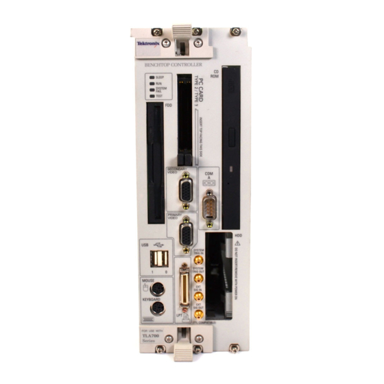
Page 59: Figure 2- 9: Front View Of The Benchtop Controller
Replaceable Hard Disk Drive SYSTEM TRIG IN USB Ports (2) SYSTEM TRIG OUT Mouse EXTERNAL SIG IN Keyboard EXTERNAL SIG OUT Figure 2- 9: Front view of the benchtop controller 2- 16 TLA721 Benchtop & TLA7XM Expansion Mainframe Service Manual... -
Page 60: Table 2- 6: Mouse Port Pin Assignments
The keyboard port can be connected to an external, standard PS/2-compliant keyboard. Table 2- -7 lists the pin assignments. Table 2- 7: Keyboard port pin assignments Pin number Pin Assignment Data No connection +5 V Clock 2- 17 TLA721 Benchtop & TLA7XM Expansion Mainframe Service Manual... - Page 61 There are two PC Card Bus slots. The PC card(s) can be inserted in either slot, or two cards can occupy both slots at the same time. The PC card port supports an optional Ethernet NIC (network interface card). Table 2- -8 shows the pin assignments. 2- 18 TLA721 Benchtop & TLA7XM Expansion Mainframe Service Manual...
-
Page 62: Table 2- 8: Pc Cardbus32 Port Pin Assignments
USB complaint device. Table 2- -9 shows the pin assignments for the USB ports. Table 2- 9: USB pin assignments Pin number Pin function Pin number Pin function A DATA - - B DATA - - A DATA + B DATA + 2- 19 TLA721 Benchtop & TLA7XM Expansion Mainframe Service Manual... -
Page 63: Table 2- 10: Svga Out Pin Assignments
This connector is a sub-miniature bayonet (SMB) connector. Ext Sig In Connector The external signal Input is a TTL compatible input signal that is user definable in software. This connector is a sub-miniature bayonet (SMB) connector. 2- 20 TLA721 Benchtop & TLA7XM Expansion Mainframe Service Manual... -
Page 64: Table 2- 12: Lpt Port Pin Assignments
Table 2- 12: LPT port pin assignments Pin number Pin function Pin number Pin function BUSY SLCT ACK* ERR* INIT* STB* SLIN* AFD* See IEEE specification P1284-C for pin connection definitions for other modes 2- 21 TLA721 Benchtop & TLA7XM Expansion Mainframe Service Manual... -
Page 65: Figure 2- 10: Front View Of The Benchtop Controller
TTL signals, the other connector handles ECL signals. The cables for the three connectors connect to another expansion module in the host benchtop mainframe (or portable mainframe). Figure 2- 10: Front view of the benchtop controller 2- 22 TLA721 Benchtop & TLA7XM Expansion Mainframe Service Manual... - Page 66 The application software controls data acquisition and processing by the logic analyzer. The application software is included with the product; refer to the Tektronix Logic Analyzer Family User Manual if you need to reinstall any software.
- Page 67 DSO. Other Windows Other windows may exist on the logic analyzer depending on the installed setup. For more information on the logic analyzer application, refer to the Tektronix Logic Analyzer Family User Manual. 2- 24 TLA721 Benchtop & TLA7XM Expansion Mainframe Service Manual...
- Page 68 TLA721 Benchtop Mainframe and the TLA7XM Expansion Mainframe. The two mainframes are identical with the following exceptions: H The TLA721 Benchtop Mainframe includes a plug-in controller that controls the operation of the entire system. H The TLA7XM Expansion Mainframe includes an expansion module that routes signals from another external mainframe to the expansion mainframe.
-
Page 69: Figure 3- 1: Interconnection And Block Diagram For The Benchtop Mainframe And Controller
Instrument TI PCI1251B controls the two CardBus 32 slots. A Silicon Motion Lynx3DM SVGA/XGA display controller with up to 4 MB of internal DRAM supports both the integrated color TFT LCD flat panel and external SVGA port. 3- 2 TLA721 Benchtop & TLA7XM Expansion Mainframe Service Manual... - Page 70 MODID control lines. Trigger Crossbar ASIC The trigger lines are managed through the Tektronix-designed Trigger Crossbar (VTC) ASIC. The VTC ASIC cross connects any of the ten backplane trigger lines (ECL and TTL) to any of the four SMB connector ports on the front panel.
- Page 71 The benchtop and expansion mainframes are identical and contain the following major modules: H Power supply H Backplane H Enhanced monitor board H Temperature sense board Refer to Figure 3- -2 while reading the following paragraphs on the mainframe. 3- 4 TLA721 Benchtop & TLA7XM Expansion Mainframe Service Manual...
-
Page 72: Figure 3- 2: Mainframe Block Diagram
(from 45 Hz to 66 Hz) and 100 to 132 VAC (from 360 Hz to 440 Hz). This covers virtually all international power combinations. The power supply also supports automatic power factor correction and over-voltage, current, and thermal protection mechanisms. 3- 5 TLA721 Benchtop & TLA7XM Expansion Mainframe Service Manual... - Page 73 308 CFM of airflow through the mainframe at full speed. The blower connects to the enhanced monitor board at FAN 1/Blower (J8). The fan speed switch (S1) lets you select either variable fan speed (VAR) or full speed (FULL). 3- 6 TLA721 Benchtop & TLA7XM Expansion Mainframe Service Manual...
- Page 74 The CLK10 is transmitted to the expansion mainframe from the benchtop mainframe. Power On Sequence On power up, the expansion module determines correct configuration of the expansion modules and the expansion cables. 3- 7 TLA721 Benchtop & TLA7XM Expansion Mainframe Service Manual...
-
Page 75: Figure 3- 3: Benchtop And Expansion Mainframe Block Diagram
Automatic power on and automatic power off only work when the primary power switch on the expansion mainframe is closed. 3- 8 TLA721 Benchtop & TLA7XM Expansion Mainframe Service Manual... - Page 76 Performance Verification Procedures This chapter contains procedures for functional verification, certification, and performance verification procedures for the TLA721 Benchtop Mainframe and TLA7XM Expansion Mainframe. Generally, you should perform these proce- dures once per year or following repairs that affect certification.
-
Page 77: Figure 4- 1: Calibration/Certification Procedure Flow Chart
Enter measurements on Configure customer’s the appropriate mainframe and modules as Calibration Data Report. described in procedure. Create necessary Calibration Certificate. all certifications complete? Done Figure 4- 1: Calibration/certification procedure flow chart 4- 2 TLA721 Benchtop & TLA7XM Expansion Mainframe Service Manual... -
Page 78: Table 4- 1: Test Equipment
If you have an expansion mainframe, these procedures assume that the expansion mainframe is properly connected to the TLA721 Benchtop Mainframe. If necessary, refer to the Tektronix Logic Analyzer Family User Manual for installation instructions. Table 4- 2: Functional verification procedures... - Page 79 Power-on and Fan Complete the following steps to check the power-on and fan operation of the Operation TLA721 Benchtop Mainframe and the TLA7XM Expansion mainframe (if installed). You will need a mainframe with an LA or DSO module installed in each mainframe.
- Page 80 To run these diagnostics, do the following steps: 1. Quit the logic analyzer application. 2. Click the Windows Start button. 3. Select Programs → Tektronix Logic Analyzer → TLA Mainframe Diagnos- tics. 4. Run the mainframe diagnostics. CheckIt Utilities CheckIt Utilities is a comprehensive software application used to check and verify the operation of the PC hardware in the portable mainframe.
-
Page 81: Table 4- 3: Performance Verification Procedures
There are no certifiable parameters for the TLA7XM Expansion Mainframe. Performance Verification Procedures This section contains procedures to verify that the TLA721 Benchtop Mainframe and the TLA7XM Expansion Mainframe perform as warranted. Verify instru- ment performance whenever the accuracy or function of your instrument is in question. -
Page 82: Figure 4- 2: Benchtop And Expansion Mainframe 25-Pin Rear Panel Connector
11.64 V to 12.60 V +24 V 23.28 V to 25.20 V - - 5.2 V - - 5.460 V to - - 5.044 V 9, 17- - 20, 22, 24 Logic Ground 4- 7 TLA721 Benchtop & TLA7XM Expansion Mainframe Service Manual... - Page 83 10 MHz ±1 kHz. Record the measurement on a copy of the calibration data report and disconnect the frequency counter. 6. In the System Configuration dialog box, reset the External Signal Out signal to None. 4- 8 TLA721 Benchtop & TLA7XM Expansion Mainframe Service Manual...
- Page 84 Calibration Data Report TLA721 Benchtop Mainframe Instrument model number: Serial number: Certificate number: Verification performed by: Verification date: System Clock Test Data Procedure reference Characteristic Specification Tolerance Incoming data Outgoing data ±1 kHz (9.9990 MHz-10.0010 MHz) Clock frequency 10 MHz...
- Page 86 Adjustment Procedures There are no adjustments for the TLA721 Benchtop Mainframe or TLA7XM Expansion Mainframe. For adjustment procedures on the individual modules, refer to the appropriate module service manual. 5- 1 TLA721 Benchtop & TLA7XM Expansion Mainframe Service Manual...
- Page 87 Adjustment Procedures 5- 2 TLA721 Benchtop & TLA7XM Expansion Mainframe Service Manual...
- Page 88 Maintenance This chapter provides information and procedures for inspecting, cleaning, removing and replacing components, and troubleshooting the TLA721 Benchtop Mainframe and the TLA7XM Expansion Mainframe. The procedures isolate problems to a module lever rather than a component level. This chapter is divided up as follows:...
- Page 89 Immediately repair defects that could cause personal injury or lead to further damage to the benchtop controller, expansion module, or the mainframes that the module plug into. 6- 2 TLA721 Benchtop & TLA7XM Expansion Mainframe Service Manual...
-
Page 90: Table 6- 1: External Inspection Check List
Installation Procedures for detailed information on cover removal. Inspect the internal portions of the modules and the mainframes for damage and wear using Table 6- -2 as a guide. Defects found should be repaired immediately. 6- 3 TLA721 Benchtop & TLA7XM Expansion Mainframe Service Manual... -
Page 91: Table 6- 2: Internal Inspection Check List
To clean the floppy disk drive or the CD-ROM, use commercially available floppy disk drive or CD-ROM drive cleaning kits and follow the manufacturer’s instructions. 6- 4 TLA721 Benchtop & TLA7XM Expansion Mainframe Service Manual... -
Page 92: Table 6- 3: Equipment Required To Service The Mainframes
Phillips #1 screwdriver Cable ties 4-inch tie-down straps (Tektronix part number 343-0549-00) NOTE. When installing the screws, use a torque screwdriver and tighten the screws to 8 in-lbs unless otherwise noted. 6- 5 TLA721 Benchtop & TLA7XM Expansion Mainframe Service Manual... -
Page 93: Figure 6- 1: Installing The Empty Slot Panel Fillers
Refer to Figure 6- -1 for information on installing the slot fillers. CAUTION. To avoid damage caused by heat use only Tektronix front panels; otherwise, the shutters may activate, effectively robbing airflow from installed modules. Installing the fillers provides improved cooling for installed modules, improved EMI shielding, and more accurate air temperature sensing to control the fan speeds. - Page 94 Install the blower assembly by following the removal procedures in reverse order. NOTE. When reconnecting the blower cables to the chassis, verify that you connect the blower cable to J8, 1/BLOWER. 6- 7 TLA721 Benchtop & TLA7XM Expansion Mainframe Service Manual...
-
Page 95: Figure 6- 2: Location Of Blower Assembly Screws
8-32 Captive screw/cable cover 8-32 Captive screw/fan housing 8-32 Captive 8-32 Captive screw/fan housing screw/Enhance monitor 8-32 Captive screw/fan housing Figure 6- 2: Location of blower assembly screws 6- 8 TLA721 Benchtop & TLA7XM Expansion Mainframe Service Manual... -
Page 96: Figure 6- 3: Removing The Blower Assembly
Blower assembly Figure 6- 3: Removing the blower assembly Chassis Blower assembly Shroud Screws (2) Blower Cable tie Screws (4) Screws (4) Screws (6) Figure 6- 4: Removing the blower 6- 9 TLA721 Benchtop & TLA7XM Expansion Mainframe Service Manual... -
Page 97: Figure 6- 5: Removing The Enhanced Monitor Board
3. Unscrew the two captive screws that attach the monitor board to the mainframe. 4. Slide the enhanced monitor board out of the mainframe as shown in Figure 6- -5. Monitor board Figure 6- 5: Removing the enhanced monitor board 6- 10 TLA721 Benchtop & TLA7XM Expansion Mainframe Service Manual... -
Page 98: Table 6- 4: Enhanced Monitor Board Jumpers
4. Tighten the two screws that attach the enhanced monitor board to the mainframe. 5. Connect the blower cable into the connector labeled 1/BLOWER. 6. Install the cable cover and tighten the captive screw to that attaches to the mainframe. 6- 11 TLA721 Benchtop & TLA7XM Expansion Mainframe Service Manual... -
Page 99: Figure 6- 6: Removing The Power Supply
2. Slide the power supply into the mainframe. 3. Push the power supply handle in firmly to ensure that the connectors are completely seated into the back plane connectors. 4. Reinstall the blower assembly. 6- 12 TLA721 Benchtop & TLA7XM Expansion Mainframe Service Manual... -
Page 100: Figure 6- 7: Removing The Mainframe Cover
4. After tilting the cover up about 3 inches, lift the cover straight off the instrument. Remove screws (20) Step 1 Step 2 Step 3 Figure 6- 7: Removing the mainframe cover 6- 13 TLA721 Benchtop & TLA7XM Expansion Mainframe Service Manual... - Page 101 1. Slide the card guide towards the rear of the mainframe and allow the front of the card guide to snap into place. 2. Test the card guides in the mainframe and verify that they do not move. 6- 14 TLA721 Benchtop & TLA7XM Expansion Mainframe Service Manual...
-
Page 102: Figure 6- 8: Removing The Top And Bottom Card Guides
Front Rear Removing card guides Gently pull the card guide forward until it pops out of place. Figure 6- 8: Removing the top and bottom card guides 6- 15 TLA721 Benchtop & TLA7XM Expansion Mainframe Service Manual... -
Page 103: Figure 6- 9: Replacing The Top And Bottom Nut Rails
3. Refer to Figure 6- -9 and slide the nut rail out of the hole on the side of chassis (use a small screwdriver if necessary). Remove module retaining screws. Bottom nut rail Top nut rail Figure 6- 9: Replacing the top and bottom nut rails 6- 16 TLA721 Benchtop & TLA7XM Expansion Mainframe Service Manual... - Page 104 1. Refer to Figure 6- -10 and install the temperature sense board in the main- frame as shown. 2. Make sure that the circuit board snaps into place under each retainer. 3. Reconnect the ribbon cable. 4. Reinstall the mainframe cover. 6- 17 TLA721 Benchtop & TLA7XM Expansion Mainframe Service Manual...
-
Page 105: Figure 6- 10: Removing The Temperature Sense Board
Mainframe Removal and Installation Procedures Temperature sense board Retainer Cable Figure 6- 10: Removing the temperature sense board 6- 18 TLA721 Benchtop & TLA7XM Expansion Mainframe Service Manual... -
Page 106: Figure 6- 11: Removing The Backplane Emi Din Shields
3. Remove EMI DIN shield from the backplane. Installation Install the EMI DIN shield by reversing the removal procedure. Polarization hole Screws (2) Backplane EMI DIN shield Figure 6- 11: Removing the backplane EMI DIN shields 6- 19 TLA721 Benchtop & TLA7XM Expansion Mainframe Service Manual... - Page 107 6-32 screws from the bottom (refer to Figure 6- -12 if necessary). 8. After removing all of the screws from the backplane, remove the backplane from the mainframe by sliding it out of the right side. 6- 20 TLA721 Benchtop & TLA7XM Expansion Mainframe Service Manual...
-
Page 108: Figure 6- 12: Removing The Backplane
Mainframe Removal and Installation Procedures Power switch connector Connector 6-32 Screws (17) Figure 6- 12: Removing the backplane 6- 21 TLA721 Benchtop & TLA7XM Expansion Mainframe Service Manual... -
Page 109: Figure 6- 13: Soft Power Down Jumper Setting
No Jumper installed Jumper both pins 2- - 5 2- - 5 Figure 6- 13: Soft power down jumper setting 2. Install the backplane board following the removal procedures in reverse order. 6- 22 TLA721 Benchtop & TLA7XM Expansion Mainframe Service Manual... - Page 110 On/Standby switch cable at J22 and connect it to J23. Replace the mainframe cover. Connect the momentary switch to pins 5 and 18 (return side) of the 25-pin rear panel connector. 6- 23 TLA721 Benchtop & TLA7XM Expansion Mainframe Service Manual...
-
Page 111: Figure 6- 14: Power Switch Connectors
Mainframe Removal and Installation Procedures Power switch connector Backplane Figure 6- 14: Power switch connectors 6- 24 TLA721 Benchtop & TLA7XM Expansion Mainframe Service Manual... -
Page 112: Table 6- 6: Equipment Required To Service The Benchtop Controller
Individual boards inside the controller are not individually replaceable. If you isolate faults to a circuit board, you must return the entire controller module to Tektronix for repair. CAUTION. Do not remove or install the benchtop controller or any other modules while the mainframe is powered on. -
Page 113: Figure 6- 15: Removing The Replaceable Hard Disk Drive
2. Press the latch on the front of the controller as shown in Figure 6- -15 to unlatch the hard disk drive. 3. Pull on the replaceable hard disk drive cartridge to remove it from the controller. Figure 6- 15: Removing the replaceable hard disk drive 6- 26 TLA721 Benchtop & TLA7XM Expansion Mainframe Service Manual... - Page 114 Figure 6- 16: Removing the hard disk drive from the cartridge NOTE. The remaining procedures in this section assume that the removable hard disk drive is not installed in the controller. 6- 27 TLA721 Benchtop & TLA7XM Expansion Mainframe Service Manual...
- Page 115 Install the injector/ejector handle through the front panel cutout onto the mounting post, and install the screws to secure the handle to the chassis. NOTE. The top and bottom injector/ejector handles are not interchangeable. 6- 28 TLA721 Benchtop & TLA7XM Expansion Mainframe Service Manual...
- Page 116 Remove the ten flat-head T-10 Torx-drive screws, shown in Figure 6- -18, and lift off the controller left and rear covers. Left side cover Screws (10) Rear cover Chassis Figure 6- 18: Removing and installing the left and rear covers 6- 29 TLA721 Benchtop & TLA7XM Expansion Mainframe Service Manual...
- Page 117 6. Pull the front panel off so that you can access the flat-head T-10 screws underneath the front panel (be careful so that you do not damage the cable from the COM A connector). 6- 30 TLA721 Benchtop & TLA7XM Expansion Mainframe Service Manual...
- Page 118 See Figure 6- -20. 9. Disconnect the two ribbon cables located on the rear of the hard disk interface board. 10. Slide the hard drive interface board out of the chassis. 6- 31 TLA721 Benchtop & TLA7XM Expansion Mainframe Service Manual...
- Page 119 CD-ROM drive fits into the opening at the front of the chassis. 4. Install the four flat-head T-10 screws on the top and bottom of the chassis; tighten the screws to 4 in-lbs. 6- 32 TLA721 Benchtop & TLA7XM Expansion Mainframe Service Manual...
- Page 120 9. Install the two screws on the printer port connector using a small, flat-blade screw driver. 10. Install the left side cover and the rear cover. 11. Install the ejector handles. 6- 33 TLA721 Benchtop & TLA7XM Expansion Mainframe Service Manual...
- Page 121 Figure 6- -21; tighten the screws to 1 in-lbs. 4. Tighten the fixed hard disk drive bracket T-10 Torx-drive screws to secure the fixed hard disk drive brackets to the interface board; tighten the screws to 3 in-lbs. 6- 34 TLA721 Benchtop & TLA7XM Expansion Mainframe Service Manual...
- Page 122 Screws (4) Fixed hard disk drive Ribbon cable Screws (4) Fixed hard disk drive brackets Screws (6) Figure 6- 21: Removing and installing the fixed hard disk drive and CD-ROM drive 6- 35 TLA721 Benchtop & TLA7XM Expansion Mainframe Service Manual...
- Page 123 5. Install the hard disk drive interface board and the front panel. 6. Install the covers and the injector handles. 6- 36 TLA721 Benchtop & TLA7XM Expansion Mainframe Service Manual...
- Page 124 Figure 6- 22: Removal and installation of the button battery and memory Installation Install the new battery in the battery clip. Reinstall the hard disk drive interface board, the left side and rear covers, and then the ejector handles. 6- 37 TLA721 Benchtop & TLA7XM Expansion Mainframe Service Manual...
- Page 125 3. Gently push the SO DIMM into the socket. The locking tabs on each side will engage. 4. Reinstall the hard disk drive interface board, the left side and rear covers, and then the ejector handles. 6- 38 TLA721 Benchtop & TLA7XM Expansion Mainframe Service Manual...
- Page 126 T-9 and a T-10 Torx tip driver to complete the following procedures. NOTE. The internal boards are not individually replaceable. If faults are isolated to the boards, the entire benchtop controller must be returned to a Tektronix Service Center for repair.
- Page 127 9. To separate the two boards, refer to Figure 6- -24 and remove the five T-10 screws and then carefully separate the two boards. The boards are connected by two pass through connectors 6- 40 TLA721 Benchtop & TLA7XM Expansion Mainframe Service Manual...
- Page 128 12. Lift the floppy disk drive assembly from the interface board. 13. Loosen the four Phillips screws on sides of the floppy disk drive so that you can remove the drive from the bracket. 6- 41 TLA721 Benchtop & TLA7XM Expansion Mainframe Service Manual...
- Page 129 5. Refer to Figure 6- -24 on page 6- -41 and install the processor board on the interface board making sure that the board connectors are fully seated. 6. Install the five T-10 screws that you removed earlier. 6- 42 TLA721 Benchtop & TLA7XM Expansion Mainframe Service Manual...
-
Page 130: Table 6- 7: Signal Wire Identification
14. Connect the COM cable connector to the COM connector on the processor board. 15. Reinstall the hard disk drive interface board, the covers, and the ejector handles. 6- 43 TLA721 Benchtop & TLA7XM Expansion Mainframe Service Manual... - Page 131 Benchtop Controller Removal and Installation Procedures 6- 44 TLA721 Benchtop & TLA7XM Expansion Mainframe Service Manual...
- Page 132 Table 6- -8 lists the tools you may need to replace modules in the expansion module. Table 6- 8: Equipment required to service the expansion module Item Screwdriver with a T-10 tip 3/16 inch nut driver 6- 45 TLA721 Benchtop & TLA7XM Expansion Mainframe Service Manual...
- Page 133 Figure 6- -26. NOTE. The top and bottom ejector handles are not interchangeable. 6- 46 TLA721 Benchtop & TLA7XM Expansion Mainframe Service Manual...
- Page 134 Make sure that the cover is fully seated, and with no gaps, against the front and rear chassis flanges. Secure cover with the screws removed from the top and bottom of the enclosure. 6- 47 TLA721 Benchtop & TLA7XM Expansion Mainframe Service Manual...
- Page 135 3. Remove the screws from the circuit board as shown in Figure 6- -28. 4. Remove the circuit board. Remove screws (7) Remove screws (6) Figure 6- 28: Removing the circuit board 6- 48 TLA721 Benchtop & TLA7XM Expansion Mainframe Service Manual...
- Page 136 Self servicing may impact the warranty. Check with your Tektronix Service Center before servicing. Every reasonable precaution shall be made by the service person to eliminate damage to the circuit board.
- Page 137 Expansion Module Removal and Installation Procedures 6- 50 TLA721 Benchtop & TLA7XM Expansion Mainframe Service Manual...
- Page 138 H Troubleshoot the Mainframe beginning on page 6- -68 describes troubleshoot- ing procedures for the benchtop mainframe. H Troubleshoot the Expansion Mainframe beginning on page 6- -71 describes troubleshooting procedures for the expansion mainframe and the expansion module. 6- 51 TLA721 Benchtop & TLA7XM Expansion Mainframe Service Manual...
- Page 139 Check for Common Problems Use Table 6- -9 to quickly isolate possible failures. The table lists problems related to the TLA721 Benchtop Mainframe, TLA7XM Expansion Mainframe, and TLA715 Portable Mainframe (the TLA715 Portable Mainframe is included in this section to cover instances where the TLA715 Portable Mainframe is connected to a TLA7XM Expansion Mainframe).
- Page 140 Check that the monitor is connected to the mainframe; replace the cable if necessary. If the monitor connected to the Primary Video Out port is blank, try connecting another monitor to the Secondary Video Out port; if both displays are blank, contact your local Tektronix service center.
- Page 141 LA Module merge not allowed in the Merge cable between LA modules not installed. Tektronix Logic Analyzer application LA modules are not compatible: check the merge rules in the online help and in the Tektronix Logic Analyzer Family User Manual. 6- 54...
- Page 142 Module address switches not set correctly. Power off mainframe and remove module. Set address switches to FF and reinstall module. Module failure; replace with known-good module or contact your local Tektronix service center. Mainframe failure; contact your local Tektronix service center.
- Page 143 Isolating System Problems If you have looked at Table 6- -9 and the Tektronix Logic Analyzer application fails to display any modules in the System window, you may have a system problem.
- Page 144 If ResMan32 encounters any errors (such as an unsupported instrument or application module), the resource manager will stop further communications and display information on why or at what point the instrument module was disabled. 6- 57 TLA721 Benchtop & TLA7XM Expansion Mainframe Service Manual...
- Page 145 1, LA 1, started successfully slot 3, LA 2, started successfully VISA Data Frame 0, Slot 01: la_1=1,1,4093,2027,2,0,1,7,2097152 Frame 0, Slot 03: la_2=2,3,4093,2036,2,0,1,7,2162688 Figure 6- 29: ResMan32 program output 6- 58 TLA721 Benchtop & TLA7XM Expansion Mainframe Service Manual...
- Page 146 For information on diagnostics that are run on individual product modules, refer to the appropriate service manual. H Power-on BIOS test H Power-on diagnostics H Extended diagnostics 6- 59 TLA721 Benchtop & TLA7XM Expansion Mainframe Service Manual...
- Page 147 To display the extended diagnostics, select the Extended tab in the Calibration and Diagnostics property page. Disconnect probes attached to module before starting the diagnostics. 6- 60 TLA721 Benchtop & TLA7XM Expansion Mainframe Service Manual...
- Page 148 3. Select Programs from the Start menu. 4. Select Tektronix Logic Analyzer from the Programs menu. 5. Select TLA Mainframe Diagnostics from the Tektronix Logic Analyzer menu. (Refer to the online help in the TLA Mainframe Diagnostics application for information on running the TLA Mainframe Diagnostics).
- Page 149 BIOS test encounters any problem the program displays the error on the external monitor. Table 6- -12 lists the error codes, an explanation of each error code, and actions that can be taken. Refer to the Tektronix Logic Analyzer Family User Manual for information on BIOS setup parameters and feature settings.
- Page 150 This is an optional message that can be This is a information message. enter turned on and off in CMOS setup. It is SETUP only displayed during a POST test. 6- 63 TLA721 Benchtop & TLA7XM Expansion Mainframe Service Manual...
- Page 151 Reboot the system first, then - - run SETUP application. The CMOS setup may have verify that the CMOS setup is to be redefined. configured correctly. 6- 64 TLA721 Benchtop & TLA7XM Expansion Mainframe Service Manual...
- Page 152 H Determines the logic analyzer configuration. H Executes the system controller power-on diagnostics. After completing all of the above tasks, the logic analyzer starts the Tektronix Logic Analyzer application which performs the following tasks: H Power-on diagnostics on all installed modules.
- Page 153 Figure 6- 30: Startup sequence Troubleshoot the Benchtop Controller This subsection provides additional information to help you troubleshoot the benchtop controller. The procedures assume that the benchtop mainframe is fully functional. 6- 66 TLA721 Benchtop & TLA7XM Expansion Mainframe Service Manual...
- Page 154 No special equipment is required since there are no accessible test points to measure voltages and signals within the controller. Fault Isolation Use the troubleshooting tree in Figure 6- -31 to identify problems in the benchtop controller. 6- 67 TLA721 Benchtop & TLA7XM Expansion Mainframe Service Manual...
- Page 155 Figure 6- 31: Benchtop controller troubleshooting tree Troubleshoot the Mainframe Use the following steps to troubleshoot problems in the benchtop mainframe. This procedures assume that the benchtop mainframe is not connected to any 6- 68 TLA721 Benchtop & TLA7XM Expansion Mainframe Service Manual...
- Page 156 H If the instrument has shut down due to overheating, and you have exhausted all other troubleshooting suggestions, you may have a faulty controller; replace the controller module. 6- 69 TLA721 Benchtop & TLA7XM Expansion Mainframe Service Manual...
- Page 157 (49.9 Ω) Check for failure at power supply, Supply backplane board voltages OK? (blown fuse or bad board) Power off mainframe. Mainframe OK. Figure 6- 32: Mainframe troubleshooting tree 6- 70 TLA721 Benchtop & TLA7XM Expansion Mainframe Service Manual...
- Page 158 The mounting screws will not provide enough force to seat the expansion module, and you can easily be strip the threads. 3. Power-on the mainframe and check for normal operation. 6- 71 TLA721 Benchtop & TLA7XM Expansion Mainframe Service Manual...
- Page 159 You should, however, power-on the instrument and verify that all diagnostics pass. There may be adjustment procedures required for some of the installed modules. Check the appropriate service manual for additional information. 6- 72 TLA721 Benchtop & TLA7XM Expansion Mainframe Service Manual...
- Page 160 H Type and serial number of the instrument. H Reason for returning. H A complete description of the service required. Mark the address of the Tektronix Service Center and the return address on the shipping carton in two prominent locations. 6- 73...
- Page 161 Repackaging Instructions 6- 74 TLA721 Benchtop & TLA7XM Expansion Mainframe Service Manual...
- Page 162 Options This chapter lists the advertised options and optional accessories for the TLA721 Benchtop Mainframe and the TLA7XM Expansion Mainframe. Refer to the Mechanical Parts List for a list of standard and optional accessories for the mainframes. Service Options Tektronix Service Options are available at the time you order your instrument.
- Page 163 Options Product Options The following product options are available for the TLA721 Benchtop Main- frame: H Option 1A, add 10/100 LAN CardBus/32-bit PC card, 10BaseT H Option 1C, add iView cable H Option 1K, add LACART logic analyzer cart H Option 3M, add 18-inch LCD flat panel monitor...
- Page 164 Electrical Parts List Refer to the Mechanical Parts List chapter for a complete listing and description of replaceable parts for the TLA721 Benchtop Mainframe and the TLA7XM Expansion mainframe. 8- 1 TLA721 Benchtop & TLA7XM Expansion Mainframe Service Manual...
- Page 165 Electrical Parts List 8- 2 TLA721 Benchtop & TLA7XM Expansion Mainframe Service Manual...
-
Page 166: Controller
Bridge ASIC ASIC Display and I/O Adapter Board Floppy disk drive Benchtop or Expansion Mainframe Module Slot Module Slot Module Slot Power Supply Enhanced Monitor Blower Figure 9- 1: Interconnection diagram 9- 1 TLA721 Benchtop & TLA7XM Expansion Mainframe Service Manual... - Page 167 Slot 10 Slot 11 Slot 12 Switch Figure 9- 2: Benchtop mainframe block diagram Figure 9- -3 shows the block diagram for the expansion mainframe when it is connected to a benchtop mainframe. 9- 2 TLA721 Benchtop & TLA7XM Expansion Mainframe Service Manual...
- Page 168 Buffers Expansion Cable(s) Secondary Expansion Module Control and Diagnostic Registers CPU Bus Expansion MF Buffers Backplane VXI Trigger and Clock Buffers Figure 9- 3: Benchtop and expansion mainframe block diagram 9- 3 TLA721 Benchtop & TLA7XM Expansion Mainframe Service Manual...
- Page 169 Diagrams 9- 4 TLA721 Benchtop & TLA7XM Expansion Mainframe Service Manual...
- Page 170 Mechanical Parts List This section contains a list of the replaceable parts for the TLA721 Benchtop Mainframe and the TLA7XM Expansion Mainframe. Use this list to identify and order replacement parts. Parts Ordering Information Replacement parts are available through your local Tektronix field office or representative.
- Page 171 Using the Replaceable Parts List This section contains a list of the mechanical and/or electrical components that are replaceable for the TLA721 Benchtop Mainframe and TLA7XM Expansion Mainframe. Use this list to identify and order replacement parts. The following table describes each column in the parts list.
- Page 172 NIHON KAIHEIKA IND CO LTD SCOTTSDALE, AZ 85260 7850 E GELDING DRIVE 68579 PERMATRON CORP. 11400 MELROSE ST FRANKLIN PARK, IL 60131 71400 BUSSMANN DIVISION COOPER INDUSTRIES INC ST LOUIS, MO 63178 10- 3 TLA721 Benchtop & TLA7XM Expansion Mainframe Service Manual...
- Page 173 2166 MOUNTAIN INDUSTRIAL BLVD. TUCKER, GA 30084- - 5088 TK2637 SAMSUNG ELECTRONICS 18600 BROADWICK ST RANCHO DOMINQUES, CA 90220 TK6314 MCX INC 1315 OREGON AVE KLAMATH FALLS, OR 97601- - 6540 10- 4 TLA721 Benchtop & TLA7XM Expansion Mainframe Service Manual...
- Page 174 MANUAL,TECH:SERVICE,LOGIC ANALYZER TK2548 071- - 0864- - XX MODULE,TLA7NX,TLA7PX SERIES,DP 003- - 0008- - 00 ALIGN TOOL,ELEK:6.0 L X 0.375 DIA NYLON 80009 003- - 0008- - 00 W/SCDR SHAPED ENDS 10- 5 TLA721 Benchtop & TLA7XM Expansion Mainframe Service Manual...
- Page 175 - - 6 212- - 0204- - 00 SCR, ASSY WSHR: 8- - 32 X 0625 L, PNH, PLATED 3M099 212- - 0204- - 00 CARBON STL, W/SQUARE CONE WASHER, PHILLIPS DRIVE, 10- 6 TLA721 Benchtop & TLA7XM Expansion Mainframe Service Manual...
- Page 176 Mechanical Parts List Figure 10- 1: Cabinet and chassis assembly 10- 7 TLA721 Benchtop & TLA7XM Expansion Mainframe Service Manual...
- Page 177 SCREW,MACHINE:8- - 32 X 0.188,TRH,SST POZ 0KB01 ORDER BY DESCRIPTION 211- - 1093- - 00 SCREW,MACHINE:4- - 40 X 0.25,FLH 100 DEG,STL 0KB01 211- - 1093- - 00 BLK OXIDE,T7 10- 8 TLA721 Benchtop & TLA7XM Expansion Mainframe Service Manual...
- Page 178 Mechanical Parts List Figure 10- 2: Circuit boards and chassis parts 10- 9 TLA721 Benchtop & TLA7XM Expansion Mainframe Service Manual...
- Page 179 367- - 0494- - 00 0BD 211- - 0932- - 00 SCREW: SHLDR, 8- - 32 X 0.187 OD X 0.125 L, 0.187 L 24931 PZ- - 6- - 3 10- 10 TLA721 Benchtop & TLA7XM Expansion Mainframe Service Manual...
- Page 180 Mechanical Parts List Figure 10- 3: Power supply, monitor, and fan assembly 10- 11 TLA721 Benchtop & TLA7XM Expansion Mainframe Service Manual...
- Page 181 - - 6 367- - 0489- - 00 HANDLE:INJECTOR/EJECTOR ASSEMBLY,TWO 80009 367- - 0489- - 00 WIDE VXI,WITH TTL KEYING,SPRING LOADED,PLASTIC,10% 214- - 4762- - 00 SPRING,CONICAL:SPRING,CONICAL 8X345 ORDER BY DESCRIPTION 10- 12 TLA721 Benchtop & TLA7XM Expansion Mainframe Service Manual...
- Page 182 Mechanical Parts List Figure 10- 4: Benchtop controller exploded view (covers and handles) 10- 13 TLA721 Benchtop & TLA7XM Expansion Mainframe Service Manual...
- Page 183 211- - 1081- - 00 W/SERRATIONS STRESS RELIEVED,PHL,0.0002 STL ZI PL 650- - 4272- - 00 DRIVE ASSEMBLY:REMOVEABLE HARD DISK DRIVE,MAX 80009 650- - 4272- - 00 REPLACEABLE HDD,W/O SOFTWARE INSTALLED,TLA700 10- 14 TLA721 Benchtop & TLA7XM Expansion Mainframe Service Manual...
- Page 184 Mechanical Parts List Figure 10- 5: Benchtop controller exploded view (internal parts) 10- 15 TLA721 Benchtop & TLA7XM Expansion Mainframe Service Manual...
- Page 185 SPACER, POST: 0.510L, 0.188 HEX 0.135L, 4- - 40 TK0588 129- - 1544- - 00 INT, SSTL, MOUNT TO CONNECTORS 214- - 3106- - 00 HARDWARE KIT:JACK SOCKET 53387 3341- - 1S MOUNT TO TOP CONNECTOR 10- 16 TLA721 Benchtop & TLA7XM Expansion Mainframe Service Manual...
- Page 186 Mechanical Parts List Figure 10- 6: Expansion module exploded view 10- 17 TLA721 Benchtop & TLA7XM Expansion Mainframe Service Manual...
- Page 187 012- - 1614- - 00 CA ASSY:INTEROPTIBILITY ADAPTER CABLE 060D9 012- - 1614- - 00 - - 2 174- - 4583- - 00 CA ASSY:SMB TO BNC ADAPTER 060D9 174- - 4583- - 00 10- 18 TLA721 Benchtop & TLA7XM Expansion Mainframe Service Manual...
- Page 188 Mechanical Parts List Figure 10- 7: Expansion module exploded view Figure 10- 8: IView cables 10- 19 TLA721 Benchtop & TLA7XM Expansion Mainframe Service Manual...
- Page 189 Mechanical Parts List 10- 20 TLA721 Benchtop & TLA7XM Expansion Mainframe Service Manual...
Need help?
Do you have a question about the TLA721 and is the answer not in the manual?
Questions and answers