Tektronix P6417 Instructions Manual

Tektronix P6417 Instructions Manual

Logic analyzer probes

Advertisement

Quick Links

Instructions
P6417 & P6418
Logic Analyzer Probes
071-0567-00

Advertisement

Table of Contents
loading

Summary of Contents for Tektronix P6417

  • Page 1 Instructions P6417 & P6418 Logic Analyzer Probes 071-0567-00...
  • Page 2 Copyright Tektronix, Inc. All rights reserved. Tektronix products are covered by U.S. and foreign patents, issued and pending. Information in this publication supercedes that in all previously published material. Specifications and price change privileges reserved. Printed in the U.S.A. Tektronix, Inc., P.O. Box 1000, Wilsonville, OR 97070–1000...
  • Page 3 Tektronix, with shipping charges prepaid. Tektronix shall pay for the return of the product to Customer if the shipment is to a location within the country in which the Tektronix service center is located. Customer shall be responsible for paying all shipping charges, duties, taxes, and any other charges for products returned to any other locations.
  • Page 5: Table Of Contents

    ........Replacing Podlets on the P6417 Probes .
  • Page 6 Table of Contents List of Figures Figure 1: P6417 and P6418 logic analyzer probes ....Figure 2: Attaching probe labels ......
  • Page 7: General Safety Summary

    General Safety Summary Review the following safety precautions to avoid injury and prevent damage to this product or any products connected to it. To avoid potential hazards, use this product only as specified. Only qualified personnel should perform service procedures. While using this product, you may need to access other parts of the system.
  • Page 8 General Safety Summary CAUTION. Caution statements identify conditions or practices that could result in damage to this product or other property. Terms on the Product. These terms may appear on the product: DANGER indicates an injury hazard immediately accessible as you read the marking.
  • Page 9: Preface

    Preface This document provides information on using and servicing the P6417 and P6418 Logic Analyzer probes. Related Documentation In addition to these probe instructions, the following documentation is available for your TLA 700 Series Logic Analyzer: The TLA 700 Series User Manual provides overall user information for the TLA 700 Series Logic Analyzer.
  • Page 10: Contacting Tektronix
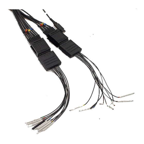
    For product support outside of North America, contact your local Tektronix distributor or sales office. Service Contact your local Tektronix distributor or sales office. Or visit Support our web site for a listing of worldwide service locations. www.tektronix.com Toll-free...
  • Page 11: Operating Basics

    Operating Basics This section provides a brief description of the P6417 and P6418 logic analyzer probes, information on attaching and using color-coded probe labels, and information on connecting the probes from the logic analyzer to the target system. Product Description The P6417 and P6418 logic analyzer probes connect a Tektronix TLA series logic analyzer to a target system.
  • Page 12: Table 1: Probe Section And Label Combinations

    2. From the sheet of labels, locate the color-coded label for the module end of the probe cable. NOTE. When you install the labels on the P6417 probe, make sure that you select the correct label for module end of the probe. The labels that connect to both ends of the probe look similar, but differ in information content.
  • Page 13: Figure 2: Attaching Probe Labels

    Operating Basics Module end Clock connector Podlet connector P6417 Probe Module end Clock connector Podlet connector P6418 Probe Figure 2: Attaching probe labels P4617 & P6418 Logic Analyzer Probe Instructions...
  • Page 14: Connecting The Probes

    Connect the logic analyzer probes and the optional retaining brackets as shown in Figure 3. The retaining brackets and hardware ship with the logic analyzer (note that the P6417 probe does not require screws to hold the retainer bracket). Match...
  • Page 15: Figure 4: Connecting The Probes To The Target System

    Operating Basics Refer to Figure 4 and connect the probe to the target system using one of the following methods: Connect the probes directly to square pins on the target system (refer to Probe Connectors on page 7 for information on probe dimensions). Connect the probes to the target system via the flying lead sets.
  • Page 16 Operating Basics Note the location of the ground connections for the probe. The individual podlets have ground (GND) engraved on the podlet. The podlet connectors have ground engraved on one side of the connector and numbers on the other side. When you use the 8-channel lead sets, the ground lead is a single, black connector.
  • Page 17: Reference

    Reference This section provides reference information and specifications for the P6417 and P6418 probes. Probe Connectors Figure 5 shows the dimensions of the probe footprints for both the P6417 and P6418 probes. 0.200 Min 0.700 0.100 0.400 0.150 0.100 0.100 0.150 Min...
  • Page 18: Loading And Equivalent Circuits

    Figure 6: Probe podlet clearance Loading and Equivalent Circuits Figure 7 shows the equivalent circuits for the purposes of estimating the loading of probes on the target system. P6417 Equivalent Circuit P6418 Equivalent Circuit 20K (LA Module) (user) 20K (LA Module)
  • Page 19: Specifications

    Reference Specifications Table 2 lists the electrical and mechanical specifications for the P6417 and P6418 probes. The electrical specifications apply when the probe is connected between a compatible logic analyzer and a target system. All specifications apply to both types of probes unless otherwise indicated.
  • Page 20: Table 3: Environmental Specifications

    Reference Table 3 shows the environmental specifications for both probes. The probes are designed to meet Tektronix standard 062-2847-00 class 5. Table 3: Environmental specifications Characteristic Description Temperature Maximum operating +50 C (+122 F) Minimum operating 0 C (+32 F) Non-operating –55 C to +75 C (–67 F to +167 F)
  • Page 21: Maintenance

    Maintenance The P6417 and P6418 Probes do not require scheduled or periodic maintenance. Use the procedures listed under Functional Check to check the basic functional- ity of the probes. To verify that the probes meet or exceed the performance requirements for...
  • Page 22 Maintenance Perform the following steps to complete the probe functional verification procedure: 1. Ensure that the jumper at J15 on the adjustment/verification fixture is in the INT position to select the internal 50.065 MHz clock. 2. Open the Setup window for the LA module which will be used to test the probes.
  • Page 23: Inspection And Cleaning

    Replacing Podlets on the P6417 Probes You can reposition or replace the individual P6417 Probe podlets, depending on your application. Use the following procedures to move or replace the podlets. P4617 & P6418 Logic Analyzer Probe Instructions...
  • Page 24: Figure 10: Moving Probe Podlets

    Maintenance Moving P6417 Probe Depending on your application, you can reposition probe podlets as shown in Podlets Figure 10. When moving podlets in the podlet holder keep the ground side of the podlets together. Remove podlet cables Pull open the podlet holder...
  • Page 25: Figure 11: Disassembling The Probe Cable

    Maintenance NOTE. If you need to replace more than one podlet, replace the podlets one at a time to avoid mixing them up. 3. Using the screwdriver with the #1 Phillips tip, remove the four screws on the probe housing on the module end of probe cable (see Figure 11). Top housing Cable header housing...
  • Page 26: Figure 12: Removing The Faulty Channel From The Probe Cable Header Housing

    Maintenance 4. Remove the top and bottom probe housings and set them aside. Do not mix the probe connector-end housings with the podlet connector housings; the labels are different at each end of the probe. 5. Identify the faulty probe channel at the module end of the cable. 6.
  • Page 27: Figure 13: Removing A Podlet Cable From The Rubber Comb

    Maintenance Remove faulty podlet cable from rubber comb Cut above color-coded ring Figure 13: Removing a podlet cable from the rubber comb 11. Attach the module end of the replacement podlet cable to the cut end of the faulty podlet cable in the following manner: a.
  • Page 28: Figure 14: Replacing A Podlet In The Podlet Holder

    Maintenance Align the ground connectors Pull open Figure 14: Replacing a podlet in the podlet holder 14. Take the color-coded ring that you removed in step 9 on page 16 and slide it onto the installation tool. (The installation tool is included in the podlet replacement kit.) CAUTION.
  • Page 29: Figure 15: Installing The Color-Coded Ring

    Maintenance Installation tool Install color-coded ring on the replacement cable and slide the ring down the tool. Replacement cable Figure 15: Installing the color-coded ring 16. Push the new podlet cable into the rubber comb. 17. Unwrap and remove the masking tape from the splice of the two cables and discard the faulty cable.
  • Page 30: Figure 16: Installing The Cable In The Cable Header Housing

    Maintenance 19. Insert the new podlet cable partially into the cable header housing. Place a new retaining snap (included with the kit) on the podlet cable as shown in Figure 16 and fully insert the cable and retaining snap into the cable header housing.
  • Page 31: Repackaging Instructions

    Reason for Returning A Complete description of the service required Seal the shipping carton. Mark the address of the Tektronix Service Center and your own return address on the shipping carton in two prominent locations. P4617 & P6418 Logic Analyzer Probe Instructions...
  • Page 32 Maintenance P4617 & P6418 Logic Analyzer Probe Instructions...
  • Page 33: Replaceable Parts

    Using the Replaceable Parts List This section contains a list of the mechanical and/or electrical components that are replaceable for your Tektronix product. Use this list to identify and order replacement parts. The following table describes each column in the parts list.
  • Page 34: Figure 17: P6417 And P6418 Probe Accessories

    WU–KU INDUSTRIAL PARK 23633 RICHEY ELECTRONICS INC 7441 LINCOLN WAY GARDEN GROVE, CA 92641 80009 TEKTRONIX INC 14150 SW KARL BRAUN DR BEAVERTON, OR 97077–0001 PO BOX 500 Figure 17: P6417 and P6418 Probe accessories P4617 & P6418 Logic Analyzer Probe Instructions...
  • Page 35 CA ASSY,SP:DESCRETE, TWO 8-CH LEAD SETS & 80009 196–3459–00 ONE 1-CH LEADSET –2 206–0364–00 TIP,PROBE:MICROCKT TEST,0.05 CTR 80009 206–0364–00 PROBE ACCESSORIES KIT FOR P6417 (020–2198–XX) 17–1 196–3459–00 CA ASSY,SP:DESCRETE, TWO 8-CH LEAD SETS & 80009 196–3459–00 ONE 1-CH LEADSET –2 206–0364–00 TIP,PROBE:MICROCKT TEST,0.05 CTR...
  • Page 36: Figure 18: P6417 Probe Exploded View

    Replaceable Parts Figure 18: P6417 Probe exploded view P4617 & P6418 Logic Analyzer Probe Instructions...
  • Page 37: Figure 19: P6418 Probe Exploded View

    Mfr. index number effective discont’d code Name & description Mfr. part number number P6417 PODLET REPLACEMENT KIT (020–2200–XX) 18–2 PODLET LATCHES –4 PODLET (INCLUDING CABLE) –5 8-CHANNEL PODLET HOLDERS –7 INSTALLATION TOOL & PODLET COLOR-CODED BANDS P6417 PROBE REPAIR KIT (020–2196–XX) 18–1...
  • Page 38 Tektronix part Serial no. Serial no. Mfr. index number effective discont’d code Name & description Mfr. part number number P6417 & P6418 OPTIONAL ACCESSORIES – 071–0266–XX MANUAL,TECH:SERVICE,TLA7LX/TLA7MX SERIES LOGIC 80009 071–0266–XX ANALYZER MODULE – 071–0265–XX MANUAL,TECH:USER,TLA700 SERIES LOGIC ANALYZER 80009 071–0265–XX –...

This manual is also suitable for:

P6418Tla714

Table of Contents