Tektronix TLA7000 Series Installation Manual
Logic analyzers
Hide thumbs
Also See for TLA7000 Series:
- Installation manual (129 pages) ,
- Technical reference manual (72 pages) ,
- Instructions manual (11 pages)
Table of Contents
Advertisement
Quick Links
TMG Corporate Website
Disclaimer:
All trademarks appearing within this PDF are trademarks of their respective owners.
Form 080/01
Complimentary Reference Material
This PDF has been made available as a complimentary service for you to assist in
evaluating this model for your testing requirements.
TMG offers a wide range of test equipment solutions, from renting short to long
term, buying refurbished and purchasing new. Financing options, such as
Financial Rental, and Leasing are also available on application.
TMG will assist if you are unsure whether this model will suit your requirements.
Call TMG if you need to organise repair and/or calibrate your unit.
If you click on the "Click-to-Call" logo below, you can all us for FREE!
TMG Products Website
Advertisement
Table of Contents

Related Manuals for Tektronix TLA7000 Series


Summary of Contents for Tektronix TLA7000 Series
- Page 1 Complimentary Reference Material This PDF has been made available as a complimentary service for you to assist in evaluating this model for your testing requirements. TMG offers a wide range of test equipment solutions, from renting short to long term, buying refurbished and purchasing new. Financing options, such as Financial Rental, and Leasing are also available on application.
- Page 2 Installation Manual TLA7000 Series Logic Analyzers 071-1747-00 Warning The servicing instructions are for use by qualified personnel only. To avoid personal injury, do not perform any servicing unless you are qualified to do so. Refer to all safety summaries prior to performing service.
- Page 3 Copyright © Tektronix, Inc. All rights reserved. Licensed software products are owned by Tektronix or its suppliers and are protected by United States copyright laws and international treaty provisions. Use, duplication, or disclosure by the Government is subject to restrictions as set forth in subparagraph (c)(1)(ii) of the Rights in Technical Data and Computer Software clause at DFARS 252.227-7013, or subparagraphs (c)(1) and (2) of the...
- Page 4 Warranty 2 Tektronix warrants that this product will be free from defects in materials and workmanship for a period of one (1) year from the date of shipment. If any such product proves defective during this warranty period, Tektronix, at its option, either will repair the defective product without charge for parts and labor, or will provide a replacement in exchange for the defective product.
- Page 5 In order to obtain service under this warranty, Customer must notify Tektronix of the defect before the expiration of the warranty period. If Tektronix is unable to provide a replacement that is free from defects in materials and workmanship within a reasonable time thereafter, Customer may terminate the license for this software product and return this software product and any associated materials for credit or refund.
-
Page 6: Table Of Contents
......... . . Connecting Accessories to the TLA7000 Series . - Page 7 ..........Index TLA7000 Series Logic Analyzer Installation Manual...
- Page 8 Figure 25: Connecting modules in a merged set ....Figure 26: Installing the merged module set in the mainframe ..TLA7000 Series Logic Analyzer Installation Manual...
- Page 9 Figure 32: TLA7012 Portable mainframe front panel ... . Figure 33: TLA7000 Series external connectors ....
-
Page 10: General Safety Summary
Do Not Operate With Suspected Failures. If you suspect there is damage to this product, have it inspected by qualified service personnel. Do Not Operate in Wet/Damp Conditions. Do Not Operate in an Explosive Atmosphere. Keep Product Surfaces Clean and Dry. TLA7000 Series Logic Analyzer Installation Manual... - Page 11 Symbols on the Product. The following symbols may appear on the product: Protective Ground CAUTION WARNING Chassis Ground Refer to Manual High Voltage (Earth) Terminal Mains Disconnected Mains Connected Standby OFF (Power) ON (Power) TLA7000 Series Logic Analyzer Installation Manual...
-
Page 12: Service Safety Summary
Use Care When Servicing With Power On. Dangerous voltages or currents may exist in this product. Disconnect power, remove battery (if applicable), and disconnect test leads before removing protective panels, soldering, or replacing components. To avoid electric shock, do not touch exposed connections. TLA7000 Series Logic Analyzer Installation Manual... - Page 13 Service Safety Summary viii TLA7000 Series Logic Analyzer Installation Manual...
-
Page 14: Environmental Considerations
Restriction of Hazardous This product has been classified as Monitoring and Control equipment, and is Substances outside the scope of the 2002/95/EC RoHS Directive. This product is known to contain lead, cadmium, mercury, and hexavalent chromium. TLA7000 Series Logic Analyzer Installation Manual... - Page 15 Environmental Considerations TLA7000 Series Logic Analyzer Installation Manual...
-
Page 16: Preface
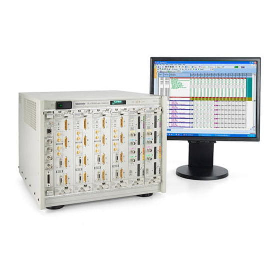
Be sure to follow all warnings, cautions, and notes in this manual. TLA7000 Series Logic Analyzers The TLA7000 Series Logic Analyzers are comprised of a 2- -module portable mainframe (TLA7012), and a 6- -module benchtop mainframe (TLA7016). See Figure i and Figure ii. -
Page 17: Figure I: Tla7012 Portable Mainframe
All of the logic analyzer modules provide simultaneous state and timing measurements through a single probe. For a complete list of accessories, refer to Appendix C: Accessories and Options. TLA7000 Series Logic Analyzer Installation Manual... -
Page 18: Figure Ii: Tla7016 Benchtop Mainframe
Preface Network connected mainframe Locally-controlled benchtop mainframe Figure ii: TLA7016 Benchtop Mainframe xiii TLA7000 Series Logic Analyzer Installation Manual... -
Page 19: Documentation
The following table lists related documentation available for your logic analyzer. The documentation is available on the TLA Documentation CD and on the Tektronix website (www.Tektronix.com). For documentation not specified in the table, contact your local Tektronix representative. Table i: Related Documentation... -
Page 20: Basic Installation
Basic Installation This chapter describes all of the steps needed to install your Tektronix logic analyzer and its related accessories. It is written from the perspective that you purchased most of the items uninstalled and you intend to install all of the pieces. -
Page 21: Environmental Considerations
TLA7016 Benchtop Mainframe. See Installing the Bracket Kit on page 8. TLA7000 Series Logic Analyzer Installation Manual... -
Page 22: Mainframe Interconnections
TLA7012 Portable optional display Portable mainframe setup (up to 2 LA modules) TLA7016 Benchtop GbE Switch TLA7PC1 Tek PC Customer supplied PC Benchtop mainframe setup (up to 6 LA modules) Figure 1: Basic standalone connections TLA7000 Series Logic Analyzer Installation Manual... -
Page 23: Figure 2: Network Switch
24.) The online help also has related information. If you want to enable a firewall on your network, Windows provides details for changing firewall settings in the Control Panel. Customer supplied PC TLA7012 Portable GbE Switch Figure 4: Portable LAN connections TLA7000 Series Logic Analyzer Installation Manual... -
Page 24: Teklink
TekLink TekLink is a mainframe real-time communication system that uses a cable to connect between two TLA7000 Series logic analyzers. An eight-port hub (TL708EX Hub) and cables are used for interconnecting from three to a maximum of eight benchtop mainframes. See Figure 6. -
Page 25: Figure 6: Tl708Ex Hub And Teklink Cable
TekLink connector on your expansion mainframe. 3. Connect the power cord to the back of the hub and to an appropriate AC power source. Figure 6: TL708EX Hub and TekLink cable TLA7000 Series Logic Analyzer Installation Manual... -
Page 26: Figure 7: Expanded Benchtop System With Tl708Ex Hub (Up To 48 Modules)
Figure 7 shows the hub connected to accomodate eight mainframes (48 modules total). GbE Switch TLA7016 Benchtop TLA7016 Benchtop TLA7PC1 Tek PC Customer supplied PC TL708EX Hub Figure 7: Expanded benchtop system with TL708EX Hub (up to 48 modules) TLA7000 Series Logic Analyzer Installation Manual... -
Page 27: Installing The Bracket Kit
6. Using the screws provided, fasten the components to the brackets. GbE Switch TL708EX Hub Bracket TLA7PC1 Tek PC Bracket Screws Screws TLA7016 Benchtop Mainframe Figure 8: Bracket kit for the TL708EX Hub and PC Controller installed TLA7000 Series Logic Analyzer Installation Manual... -
Page 28: Chassis Ground Connections
CAUTION. To reduce the risk of ground-loop noise, ground all of the instruments in the system to the logic analyzer mainframe using the ground connections shown. Chassis ground Ground screw (Benchtop mainframe only) Figure 9: Location of the ground connection on the TLA7000 logic analyzers TLA7000 Series Logic Analyzer Installation Manual... -
Page 29: Installing Tla700 Modules
Basic Installation Installing TLA700 Modules TLA700 Modules are fully compatible with the TLA7000 Series mainframes. This section describes how to install TLA700 modules in your TLA7000 mainframe. CAUTION. To avoid damaging the instrument, do not install or remove any modules while the instrument is powered on. Always power down the instrument before installing or removing modules. -
Page 30: Merging Modules
You can merge modules together to create wider modules. If your application requires you to merge modules, refer to Merging TLA700 Modules (beginning on page 29) for the merge instructions before continuing with this section. TLA7000 Series Logic Analyzer Installation Manual... -
Page 31: Installing Modules In The Tla7012 Portable Mainframe
H When installing a logic analyzer module with an oscilloscope module, install the logic analyzer module in slots 1- -2 and the oscilloscope module in slots 3- -4. Place double-width slot covers over slots 5- -6, 7- -8, 9- -10, and 11- -12. TLA7000 Series Logic Analyzer Installation Manual... -
Page 32: Figure 11: Installing Modules
Basic Installation Use a screwdriver to tighten the retaining screws to 2.5 in-lbs after seating the modules in place. See Figure 11. Portable mainframe Benchtop mainframe Retaining screws Injector/ejector handles Figure 11: Installing modules TLA7000 Series Logic Analyzer Installation Manual... -
Page 33: Covering Empty Slots
EMC and cooling specifications. Install a blank-slot panel cover for each empty slot as shown in Figure 12 or 13. The blank-slot panel covers must be installed first, before any modules. Use only Tektronix TLA covers; otherwise the mainframe may not meet EMC and cooling requirements. -
Page 34: Connecting Accessories
Secondary Speaker and DVI- - I micophone DVI- - D EXTERNAL SIG OUT EXTERNAL SIG IN Activity light TekLink EXTERNAL TRIG OUT EXTERNAL TRIG IN Portable mainframe (rear view) Figure 14: TLA7012 accessories connections TLA7000 Series Logic Analyzer Installation Manual... -
Page 35: Additional Accessory Connection Information
The TLA7016 Benchtop Mainframe can also support the related hardware in a stacked, benchtop configuration using the optional bracket kit. See page 8 for instructions on mounting the support hardware to the benchtop mainframe. TLA7000 Series Logic Analyzer Installation Manual... -
Page 36: Connecting Probes
Connect the logic analyzer probes as shown in Figure 16 and Figure 17. Logic Analyzer Module Probe Match color- - coded labels Figure 16: Connecting the P69xx logic analyzer probes to the TLA7Axx logic analyzer module TLA7000 Series Logic Analyzer Installation Manual... -
Page 37: Configuring And Connecting The Pattern Generator Probes
TLA7PG2 Probe Instruction Manual for information about how to change the series termination resistors. Always power off the logic analyzer before connecting the pattern generator probes to the logic analyzer and to the target system. TLA7000 Series Logic Analyzer Installation Manual... -
Page 38: First Time Operation
103 V to 250 V operation 15 A, fast blow, 125 V 159-0256-xx 207 V to 250 V operation 6.3 A, fast blow, 250 V 159-0381-xx AC power and fuse Figure 18: Line fuse and power cord connector locations TLA7000 Series Logic Analyzer Installation Manual... -
Page 39: Turning On Expansion Mainframes
Both the portable and benchtop mainframes have a built-in soft power-off function that safely powers off the mainframe when you press the On/Standby switch. The expansion mainframes automatically power off when you turn off the benchtop or portable mainframe. TLA7000 Series Logic Analyzer Installation Manual... -
Page 40: Performing The Incoming Inspection
To check the P69xx logic analyzer probes, connect the probes to a signal source, Analyzer Probes start an acquisition, and verify that the acquired data is displayed in either the listing or waveform windows. (Optional) TLA7000 Series Logic Analyzer Installation Manual... -
Page 41: Checking The P64Xx Logic Analyzer Probes (Optional)
Back up your user files on a regular basis. Use the Windows back up tools or copy the files to another media. Always keep a backup copy of files that you access on a regular basis. TLA7000 Series Logic Analyzer Installation Manual... -
Page 42: Removing The Replaceable Hard Disk Drive (Tla7012 Only)
The logic analyzer connects to the target system through the probes. The logic analyzer probes allow you to connect to the target system in several different ways. For probe-specific connection details, refer to the appropriate probe instruction manual or browse through the Tektronix website. TLA7000 Series Logic Analyzer Installation Manual... -
Page 43: Connecting To A Network
PC. To start the TLA server on the portable mainframe, do the following: 1. Click Start → All Programs → Tektronix Logic Analyzer → TLA Server. An icon with a red circle appears in the Windows toolbar. -
Page 44: Figure 21: Tla Connection Dialog Box
If no instruments are displayed in the Connection dialog box: a. Click the Search icon to open the TLA Network Search dialog box. (See Figure 22.) TLA7000 Series Logic Analyzer Installation Manual... -
Page 45: Figure 22: Tla Network Search Dialog Box
In Use, Power Off, Server Down, Blank (available), etc. 10. Select the mainframe you want to connect to and click the Connect button. The application opens on the remote instrument and displays on your PC. TLA7000 Series Logic Analyzer Installation Manual... - Page 46 1. Start the software by double- -clicking the TLA Application icon. 2. From the TLA Connection dialog box, click Offline to start an offline version of the TLA application software. TLA7000 Series Logic Analyzer Installation Manual...
- Page 47 Basic Installation TLA7000 Series Logic Analyzer Installation Manual...
-
Page 48: Merging Tla700 Modules
H The logic analyzer modules must have the same firmware version. H The maximum merged combinations are two TLA7Lx and TLA7Mx logic analyzer modules; three TLA7Nx, TLA7Px, or TLA7Qx logic analyzer modules; and five TLA7Axx logic analyzer modules. TLA7000 Series Logic Analyzer Installation Manual... -
Page 49: Tla7Pg2 Pattern Generator Module Merging Rules
1. Determine which modules will reside in the highest-numbered slots in a single mainframe. 2. Place the merge connector of these modules in the extended position. The module in the lowest-numbered slot must have the merge connector in the recessed position. TLA7000 Series Logic Analyzer Installation Manual... -
Page 50: Merging Tla7Axx Logic Analyzer Modules
Complete the following steps to create a merged module from two to five individual TLA7Axx modules. 1. Place the module on the right side. 2. Using a Torx T-10 screwdriver, remove the two screws holding the merge connector to the module (see Figure 24). TLA7000 Series Logic Analyzer Installation Manual... -
Page 51: Figure 24: Removing The Merger Connector Assembly From The Module
6. Place the first pair of modules to be merged side-by-side such that the merge connector assemblies line up and connect between the two modules (see Figure 25). 7. Push the two modules together until the connectors are seated in place. TLA7000 Series Logic Analyzer Installation Manual... -
Page 52: Figure 25: Connecting Modules In A Merged Set
10. Align the tops and bottoms of the modules with the slots in the mainframe (see Figure 26 on page 34). You may need the help of another individual if your merged module set contains more than two modules. TLA7000 Series Logic Analyzer Installation Manual... -
Page 53: Figure 26: Installing The Merged Module Set In The Mainframe
Latch in place Figure 26: Installing the merged module set in the mainframe 11. Slide the modules all the way into the mainframe until they rest against the rear panel connectors. TLA7000 Series Logic Analyzer Installation Manual... -
Page 54: Unmerging Tla7Axx Logic Analyzer Modules
9. Install the two Torx T-10 screws onto the assembly and tighten the screws to 4 in-lbs. 10. Repeat steps 7 through 9 for the other modules. You can now reinstall the modules in the mainframe as needed. TLA7000 Series Logic Analyzer Installation Manual... -
Page 55: Merging Tla7Lx/Mx/Nx/Px/Qx Logic Analyzer Modules
6. Remove the screws holding the merge cable bracket to the cover. 7. Remove the top part of the cable bracket and set it aside. 8. Remove the module cover and locate the merge cable. TLA7000 Series Logic Analyzer Installation Manual... - Page 56 9. Replace the cover while feeding the merge cable through the hole in the cover (see Figure 28). NOTE. Do not twist the cable while feeding it through the hole. If the cable is twisted, the modules will not merge correctly. TLA7000 Series Logic Analyzer Installation Manual...
- Page 57 14 through 19. If the cover is not properly seated, the module can be damaged when you install it in the mainframe and it may not meet EMC requirements. TLA7000 Series Logic Analyzer Installation Manual...
- Page 58 (two on the top and two on the bottom) to secure the cover to the chassis. 16. Install the screws near the front of the module. 17. Slide the rear panel on the chassis and install the rear panel screws. TLA7000 Series Logic Analyzer Installation Manual...
- Page 59 22. Slide the modules all the way into the mainframe until they rest against the rear panel connectors. 23. Use the injector handles to firmly seat the modules in place one at a time. 24. Tighten the four retaining screws on each module to 2.5-in. lbs. TLA7000 Series Logic Analyzer Installation Manual...
-
Page 60: Three-Way Logic Analyzer Merge Procedure
3. Remove the screws from the side cover and rear cover. 4. Push the merge cable through the side cover and remove the cover. 5. Position the merge cable as shown in Figure 31. TLA7000 Series Logic Analyzer Installation Manual... - Page 61 11. Install the merge cable bracket so that the guide pins point into the module. 12. Install and tighten the screws on the merge cable bracket. 13. Verify that you have installed and tightened all screws on the module. TLA7000 Series Logic Analyzer Installation Manual...
-
Page 62: Product Overview
Navigation controls MagniVu Search Scrolls data vertically Scrolls data horizontally Changes the height of Changes Time/Div in selected waveform the Waveform window (Waveform window only) Ctrl Shift Figure 32: TLA7012 Portable mainframe front panel TLA7000 Series Logic Analyzer Installation Manual... -
Page 63: Tla7000 Series External Connectors
EXTERNAL SIG OUT SYSTEM TRIG OUT EXTERNAL SIG IN SYSTEM TRIG IN TekLink TekLink SYSTEM TRIG OUT SYSTEM TRIG IN Portable mainframe (rear view) Benchtop mainframe (front view) Figure 33: TLA7000 Series external connectors TLA7000 Series Logic Analyzer Installation Manual... -
Page 64: Restoring And Reinstalling Software
These instructions only refer to reinstalling the application software and operating system. If you want to upgrade to a newer application software version and operating system, contact your local Tektronix representative about purchasing the TLA7KUP field upgrade kit. This section also provides informa- tion on installing related logic analyzer software on a PC for remote operation or for offline applications. -
Page 65: Flashing The Bios
BIOS settings are corrupted or lost. To configure the Controller BIOS, complete the following steps: 1. Power on the logic analyzer and press function key F2 before the logic analyzer boots the Windows operating system. TLA7000 Series Logic Analyzer Installation Manual... - Page 66 6. Under Video Configuration, set the Primary Video Adapter to PCI. 7. Press function key F10 to exit and save the BIOS settings and then continue with the disk image installation procedure on page 48. TLA7000 Series Logic Analyzer Installation Manual...
-
Page 67: Reinstalling The Hard Disk Image
Restoring and Reinstalling Software Reinstalling the Hard Disk Image The Tektronix Logic Analyzer comes with CDs containing the Microsoft Windows operating system and the latest application software. All software required to run the logic analyzer comes with the CDs except for any micropro- cessor support packages or non-logic analyzer application software. -
Page 68: Installing The Operating System And Tla Application Software
Restoring and Reinstalling Software the Tektronix Support Center (refer to Contacting Tektronix at the beginning of this document). NOTE. You can reinstall the Microsoft Windows operating system and other software only from the Hard Disk Image CDs that came with your instrument. - Page 69 5. Reinstall any user files that you backed up previously. Reinstall any software (such as the microprocessor support packages) that you want to use on the logic analyzer. 6. If desired, reconfigure the TLA network interface. TLA7000 Series Logic Analyzer Installation Manual...
-
Page 70: Reinstalling The Tla Application Software
You can analyze previously acquired data from a logic analyzer, create or modify reference memo- ries, or perform system tests without being connected to a real instru- ment. TLA7000 Series Logic Analyzer Installation Manual... -
Page 71: Installing The Tpi Remote Operation Software
PC. If you have an older version already installed on your PC, the program will automatically detect it and replace it during the upgrade process. 1. Install the Tektronix Logic Analyzer Family Application Software CD in the CD drive of the PC. -
Page 72: Upgrading Or Restoring Firmware
If any modules indicate invalid or similar messages, you must update the firmware for those modules. 2. Exit the logic analyzer application. 3. Click Start → Programs → Tektronix Logic Analyzer → TLA Firmware Loader. When the firmware loader is operated on portable instruments only, you are given a choice to load Mainframe or Instrument Module Firmware. - Page 73 16. Verify that the firmware version for the selected module matches the version on the label that you recorded in step 12. 17. If the firmware versions do not match, power down the mainframe, remove the module from the mainframe and update the label. TLA7000 Series Logic Analyzer Installation Manual...
-
Page 74: Upgrading Firmware On Tla7Lx/Mx/Nx/Px/Qx/Dx/7Ex Modules
8. Wait for the TLA application to start. NOTE. Any modules with the flash programming jumper installed will not display in the System window. 9. Exit the TLA application (and pattern generator application if you have it installed on your instrument). TLA7000 Series Logic Analyzer Installation Manual... - Page 75 Restoring and Reinstalling Software Flash programming pins Figure 34: Flash programming pins 10. Click Start → Programs → Tektronix Logic Analyzer → TLA Firmware Loader. 11. Select the modules that you want to update from the list of modules displayed in the Supported list box near the top of the window. This selects the modules for the upgrade.
-
Page 76: Table 5: Tla Firmware Files
24. Verify that the firmware version for the selected module matches the version on the label that you recorded in step 20. 25. If the firmware versions do not match, power down the mainframe, remove the module from the mainframe and update the label. TLA7000 Series Logic Analyzer Installation Manual... -
Page 77: Upgrading Firmware On Tla7Pg2 Pattern Generator Modules
System window. 9. Exit the pattern generator application (and the TLA application). 10. Click Start → Programs → Tektronix Logic Analyzer → TLA Firmware Loader. 11. Select the modules that you want to update from the list of modules displayed in the Supported list box near the top of the window. - Page 78 24. Verify that the firmware version for the selected module matches the version on the label that you recorded in step 20. 25. If the firmware versions do not match, power off the mainframe, remove the module from the mainframe and update the label. TLA7000 Series Logic Analyzer Installation Manual...
- Page 79 8. As the flash operation runs, it identifies what steps are being performed. When complete, it will inform you to reboot the system you just flashed. 9. Turn off and restart the TLA system after the flash operation is complete. TLA7000 Series Logic Analyzer Installation Manual...
-
Page 80: Appendix A: Mainframe Power Information
4. Refer to Figure 35 on page 63 to determine the proper line fuse for your mainframe. Table 6: Power for instrument modules Module type Power (Watts) One TLA7016 Benchtop Mainframe TLA7AA1 TLA7AA2 TLA7AA3 TLA7AA4 TLA7AB2 TLA7AB4 TLA7NA1 TLA7NA2 TLA7NA3 TLA7NA4 TLA7Q2 TLA7Q4 TLA7P2 TLA7P4 TLA7000 Series Logic Analyzer Installation Manual... - Page 81 Table 6: Power for instrument modules (Cont.) Module type Power (Watts) TLA7N1 TLA7N2 TLA7N3 TLA7N4 TLA7L1 TLA7L2 TLA7L3 TLA7L4 TLA7M1 TLA7M2 TLA7M3 TLA7M4 TLA7D1 TLA7D2 TLA7E1 TLA7E2 TLA7PG2 Power for mainframe with fans operating at maximum speed. TLA7000 Series Logic Analyzer Installation Manual...
- Page 82 Select the proper fuse based on the ranges shown in Figure 35. Power Cord with 20A plug (NEMA 5- - 20P) ONLY! Input Line Voltage (Volts AC) 20AT Fuse 15AF Fuse 6.3AF Fuse Figure 35: Fuse identification chart TLA7000 Series Logic Analyzer Installation Manual...
- Page 83 Appendix A: Mainframe Power Information TLA7000 Series Logic Analyzer Installation Manual...
-
Page 84: Appendix B: User Service Procedures
Service Offerings Tektronix provides service to cover repair under warranty as well as other services that are designed to meet your specific service needs. Whether providing warranty repair service or any of the other services listed below, Tektronix service technicians are well equipped to service the logic analyzers. -
Page 85: Preventive Maintenance
(calibrated). This service must be performed by a qualified service technician using the procedures outlined in the appropriate service manual for the Tektronix Logic Analyzer product. Preventive maintenance mainly consists of periodic cleaning. Periodic cleaning reduces instrument breakdown and increases reliability. Clean the instrument as needed, based on the operating environment. -
Page 86: In Case Of Problems
Many software problems can be due to corrupted or missing software files. In most cases the easiest way to solve software problems is to reinstall the software TLA7000 Series Logic Analyzer Installation Manual... -
Page 87: Hardware Problems
Start menu under the Tektronix Logic Analyzer programs. Repacking for Shipment If a mainframe or module is to be shipped to a Tektronix service center for repair, attach a tag to the mainframe or module showing the owner’s name and address, the serial number, and a description of the problem(s) encountered and/or service required. -
Page 88: Appendix C: Accessories & Options
Jumper with pull- - tab (used for flashing module FW) 131-4356-00 Quick Start User Manual 071-1236-xx Windows XP Professional with TLA Application Software V5.0 Product Software CD Operating System Restore CD TLA Documentation CD NIST, Z540-1, and ISO9000 Calibration Certificate TLA7000 Series Logic Analyzer Installation Manual... -
Page 89: Table 8: Standard Accessories, Benchtop Mainframe
Benchtop system mounting brackets: Left side 407-5127-00 Right side 407-5132-00 Windows XP Professional with TLA Application Software V5.0 Product Software CD Operating System Restore CD TLA Documentation CD NIST, Z540-1, and ISO9000 Calibration Certificate TLA7000 Series Logic Analyzer Installation Manual... -
Page 90: Table 9: Optional Accessories, Portable Mainframe
Appendix C: Accessories & Options Optional The accessories in Tables 9 and 10 are orderable for use with the mainframes at the time this manual was originally published. Consult a current Tektronix catalog for additions, changes, and details. Table 9: Optional accessories, portable mainframe... -
Page 91: Options
China power cord No power cord Field upgrades TLA7KUP Many are available. Contact Tektronix (see the beginning of the manual for contact information) for a complete list of available TLA7KUP options Service offerings Calibration services extended to cover three years... -
Page 92: Table 12: Options For Tla7Nax Modules
Initial certification plus two additional calibrations Initial certification plus four additional calibrations Add test data report Add test data report (must order Option D3) Add test data report (must order Option D5) On-site installation service TLA7000 Series Logic Analyzer Installation Manual... -
Page 93: Table 13: Options For Tla7Aax Modules
Initial certification plus two additional calibrations Initial certification plus four additional calibrations Add test data report Add test data report (must order Option D3) Add test data report (must order Option D5) On-site installation service TLA7000 Series Logic Analyzer Installation Manual... -
Page 94: Field Kit Options
(up to the end of long-term product support). To access the field-kit options that can be ordered for your modules, run the PowerFlex utility on the modules you want to upgrade. The utility will provide the correct ordering information. TLA7000 Series Logic Analyzer Installation Manual... - Page 95 Appendix C: Accessories & Options TLA7000 Series Logic Analyzer Installation Manual...
-
Page 96: Index
36 merging, 29 Extended diagnostics, 67 merging rules, 29 External, signal connectors, TLA7000 series, 44 probes, connecting LA probes TLA7000 series, 17 External connectors, 44 reinstalling software, 45 shipping list, 1 site considerations, 2 TLA7000 Series description, xi... - Page 97 20 Optional accessories, 71 Mainframe configuring P6470 pattern generator probes, 18 connecting accessories, TLA7000 series, 15 connecting LA probes, TLA7000 series, 17 diagnostics, 67 Panel cover installation, 14 equipment required to merge modules, 36 Pattern Generator module fuse location, for the portable mainframe, 19...
- Page 98 Service, user, preventive maintenance, 66 operating offline on a PC, 27 Setting the logical address, 10 TLA7000, BIOS configuration, 46 Shipping, 68 TLA7000 Series, logic analyzer description, xi Shipping list, checking, 1 Trigger, system, external signal, 44 Slot Troubleshooting, 67...
- Page 99 Index Index- 4 TLA7000 Series Logic Analyzer Installation Manual...
Need help?
Do you have a question about the TLA7000 Series and is the answer not in the manual?
Questions and answers