Tektronix TLA7000 Series Technical Reference Manual
Mainframes
Hide thumbs
Also See for TLA7000 Series:
- Installation manual (129 pages) ,
- Instructions manual (11 pages) ,
- Installation manual (109 pages)
Table of Contents
Advertisement
Quick Links
Technical Reference Manual
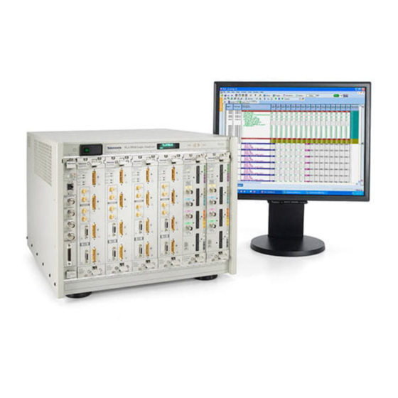
TLA7000 Series Mainframes
071-1764-00
This document applies to System Software ver-
sion 5.0 and above.
Warning
The servicing instructions are for use by qualified
personnel only. To avoid personal injury, do not
perform any servicing unless you are qualified to
do so. Refer to all safety summaries prior to
performing service.
www.tektronix.com
Advertisement
Table of Contents

Related Manuals for Tektronix TLA7000 Series


Summary of Contents for Tektronix TLA7000 Series
- Page 1 Technical Reference Manual TLA7000 Series Mainframes 071-1764-00 This document applies to System Software ver- sion 5.0 and above. Warning The servicing instructions are for use by qualified personnel only. To avoid personal injury, do not perform any servicing unless you are qualified to do so.
- Page 2 Copyright © Tektronix, Inc. All rights reserved. Licensed software products are owned by Tektronix or its subsidiaries or suppliers, and are protected by national copyright laws and international treaty provisions. Tektronix products are covered by U.S. and foreign patents, issued and pending. Information in this publication supercedes that in all previously published material.
- Page 3 Warranty 2 Tektronix warrants that this product will be free from defects in materials and workmanship for a period of one (1) year from the date of shipment. If any such product proves defective during this warranty period, Tektronix, at its option, either will repair the defective product without charge for parts and labor, or will provide a replacement in exchange for the defective product.
-
Page 5: Table Of Contents
............TLA7000 Series Mainframe Technical Reference Manual... - Page 6 ..........Mfr. Code to Manufacturer Cross Index ......TLA7000 Series Mainframe Technical Reference Manual...
- Page 7 ........TLA7000 Series Mainframe Technical Reference Manual...
- Page 8 Table of Contents List of Tables Table i: Tektronix Logic Analyzer Family documentation ..Table 1: External inspection check list ......
-
Page 9: General Safety Summary
Avoid Exposed Circuitry. Do not touch exposed connections and components when power is present. Use Proper Fuse. Use only the fuse type and rating specified for this product. Do Not Operate in Wet/Damp Conditions. TLA7000 Series Mainframe Technical Reference Manual... - Page 10 H CAUTION indicates a hazard to property including the product. The following symbols may appear on the product: Protective Ground CAUTION WARNING Standby Chassis Ground (Earth) Terminal Refer to Manual High Voltage TLA7000 Series Mainframe Technical Reference Manual...
-
Page 11: Service Safety Summary
Use Care When Servicing With Power On. Dangerous voltages or currents may exist in this product. Disconnect power, remove battery (if applicable), and disconnect test leads before removing protective panels, soldering, or replacing components. To avoid electric shock, do not touch exposed connections. TLA7000 Series Mainframe Technical Reference Manual... -
Page 12: Environmental Considerations
This product has been classified as Monitoring and Control equipment, and is Substances outside the scope of the 2002/95/EC RoHS Directive. This product is known to contain lead, cadmium, mercury, and hexavalent chromium. viii TLA7000 Series Mainframe Technical Reference Manual... -
Page 13: Preface
Included are instructions for removal and installation of replaceable parts. H Mechanical Parts List includes tables of all replaceable parts for the instrument along with the Tektronix part number. Manual Conventions This manual uses certain conventions that you should become familiar with before attempting service. -
Page 14: Related Documentation
Preface Related Documentation The following documents are available as part of the Tektronix Logic Analyzer Family documentation set. The procedures in this manual assume that the service personnel have access to the manuals listed in the following table. Contact your local Tektronix Service Representative for the latest part numbers of the service documentation. -
Page 15: Introduction
This manual does not support component-level fault isolation and replacement. Service Offerings Tektronix provides service to cover repair under warranty as well as other services that are designed to meet your specific service needs. Whether providing warranty repair service or any of the other services listed below, Tektronix service technicians are equipped to service the instrument. -
Page 16: Warranty Repair Service
Introduction Warranty Repair Service Tektronix warrants this product for one year from date of purchase. The warranty is located behind the title page in this manual. Tektronix technicians provide warranty service at most Tektronix service locations worldwide. The Tektronix product catalog lists all service locations worldwide. -
Page 17: Maintenance
5. Handle circuit boards by the edges when possible. 6. Do not slide the circuit boards over any surface. 7. Avoid handling circuit boards in areas that have a floor or work-surface covering capable of generating a static charge. TLA7000 Series Mainframe Technical Reference Manual... -
Page 18: Inspection And Cleaning
To confirm this, inspect for physical damage incurred during transit. Retain the packaging in case shipment for repair is necessary. If there is damage or deficiency, contact your local Tektronix representative. Cleaning procedures consist of exterior and interior cleaning. Periodic cleaning reduces instrument breakdown and increases reliability. -
Page 19: Exterior Cleaning Procedure
Chassis Dents, deformations, and Straighten, repair, or replace defective damaged hardware. hardware. CAUTION. To prevent damage from electrical arcing, ensure that circuit boards and components are dry before applying power. TLA7000 Series Mainframe Technical Reference Manual... -
Page 20: Interior Cleaning Procedure
75% isopropyl alcohol solution and rinse with deionized or distilled water. Clean the exterior (face) of the DVD drive and replaceable hard disk drive cartridge with a soft, clean cloth and a mild detergent. TLA7000 Series Mainframe Technical Reference Manual... -
Page 21: Portable Mainframe Removal And Installation Procedures
For motherboard and jack screw removal 9/16-inch socket For interface board removal Torque wrench 2 in-lb minimum NOTE. When installing the screws, use a torque screwdriver and tighten the screws to 8 in-lbs unless otherwise noted. TLA7000 Series Mainframe Technical Reference Manual... -
Page 22: Instrument Covers
1. Disconnect all cords, cables, and probes from the instrument. 2. Carefully remove all instrument modules (if any) from the instrument. 3. Set the instrument on the bottom feet. 4. Remove the six T-15 screws from the right cover and remove the cover. TLA7000 Series Mainframe Technical Reference Manual... -
Page 23: Figure 2: Instrument Enclosure Detail
6. Remove the four skid feet from the left side (4 T-15 screws). 7. Remove the remaining T-15 screws from the top left cover and then remove the cover. 8. Set the instrument on the rear feet. TLA7000 Series Mainframe Technical Reference Manual... -
Page 24: Front Panel Display
Figure 3: Tilt the panel forward for cable access 4. Disconnect the two display cables and three USB cables from the front panel assembly. 5. Remove the ground wire with a 5/16 in driver. TLA7000 Series Mainframe Technical Reference Manual... -
Page 25: Figure 4: Front Panel Cable Locations
See Figure 5. Route USB cables below DVD drive to prevent pinching when reinstalling Keep the ribbon cables flat against chassis Figure 5: Dress the cables properly TLA7000 Series Mainframe Technical Reference Manual... -
Page 26: Dvd Drive
5. Disconnect and pull all cables clear of the motherboard. (Refer to Figure 6 on page 11.) 6. Pass the DVD ribbon cable through chassis to clear the motherboard. 7. Move the motherboard forward to clear the USB grounding bracket and then lift board out. TLA7000 Series Mainframe Technical Reference Manual... -
Page 27: Interface Board
6. Remove the five screws securing the interface board to the chassis. To install the interface board, watch the ground fingers on top left. (Gently bend the board down while pushing it into place.) TLA7000 Series Mainframe Technical Reference Manual... -
Page 28: Backplane
5. Remove the four screws and four binding posts from the backplane board. 6. Slide the backplane under the chassis post as indicated in Figure 8 on page 13. 7. Pull out the backplane. TLA7000 Series Mainframe Technical Reference Manual... -
Page 29: Power Supply
3. Remove the eight screws (four on the bottom EMI cover and four on the side) securing the power supply to the chassis. 4. Pull out the assembly. 5. Remove the handle from the assembly. TLA7000 Series Mainframe Technical Reference Manual... - Page 30 Portable Mainframe Removal and Installation Procedures TLA7000 Series Mainframe Technical Reference Manual...
-
Page 31: Benchtop Mainframe Removal And Installation Procedures
NOTE. When installing the screws, use a torque screwdriver and tighten the screws to 8 in-lbs unless otherwise noted. WARNING. To avoid electric shock, always power off the instrument and disconnect the power cord before cleaning or servicing the instrument. TLA7000 Series Mainframe Technical Reference Manual... -
Page 32: Instrument Modules
7. Remove the four screws that hold the blower to the chassis part of the blower assembly. 8. For convenience, replace the two sheet metal screws from step 6 onto the top of the blower. Install the blower assembly by following the removal procedures in reverse order. TLA7000 Series Mainframe Technical Reference Manual... -
Page 33: Figure 9: Location Of Blower Assembly Screws
8-32 Captive 8-32 Captive screw/fan housing screw/Enhance monitor 8-32 Captive screw/cable cover 8-32 Captive screw/fan housing 8-32 Captive 8-32 Captive screw/fan housing screw/Enhance monitor 8-32 Captive screw/fan housing Figure 9: Location of blower assembly screws TLA7000 Series Mainframe Technical Reference Manual... -
Page 34: Figure 10: Removing The Blower Assembly
Power supply Cable cover Fan cable Blower assembly Figure 10: Removing the blower assembly Chassis Blower assembly Shroud Screws (2) Blower Cable tie Screws (4) Screws (4) Screws (6) Figure 11: Removing the blower TLA7000 Series Mainframe Technical Reference Manual... -
Page 35: Removing The Enhanced Monitor Board
3. Unscrew the two captive screws that attach the monitor board to the mainframe. 4. Slide the enhanced monitor board out of the mainframe as shown in Figure 12. Monitor board Figure 12: Removing the enhanced monitor board TLA7000 Series Mainframe Technical Reference Manual... -
Page 36: Table 5: Enhanced Monitor Board Jumpers
4. Tighten the two screws that attach the enhanced monitor board to the mainframe. 5. Connect the blower cable into the connector labeled 1/BLOWER. 6. Install the cable cover and tighten the captive screw to that attaches to the mainframe. TLA7000 Series Mainframe Technical Reference Manual... -
Page 37: Power Supply
2. Slide the power supply into the mainframe. 3. Push the power supply handle in firmly to ensure that the connectors are completely seated into the back plane connectors. 4. Reinstall the blower assembly. TLA7000 Series Mainframe Technical Reference Manual... -
Page 38: Mainframe Cover
3. Lift the front bottom corners up. 4. After tilting the cover up about 3 inches, lift the cover straight off the instrument. Remove screws (20) Step 1 Step 2 Step 3 Figure 14: Removing the mainframe cover TLA7000 Series Mainframe Technical Reference Manual... -
Page 39: Card Guides
1. Slide the card guide towards the rear of the mainframe and allow the front of the card guide to snap into place. 2. Test the card guides in the mainframe and verify that they do not move. 3. Reinstall the mainframe cover. TLA7000 Series Mainframe Technical Reference Manual... -
Page 40: Figure 15: Removing The Top And Bottom Card Guides
Front Rear Removing card guides Gently pull the card guide forward until it pops out of place. Figure 15: Removing the top and bottom card guides TLA7000 Series Mainframe Technical Reference Manual... -
Page 41: Temperature Sense Board
1. Refer to Figure 16 and install the temperature sense board in the mainframe as shown. 2. Make sure that the circuit board snaps into place under each retainer. 3. Reconnect the ribbon cable. 4. Reinstall the mainframe cover. TLA7000 Series Mainframe Technical Reference Manual... -
Page 42: Front Panel And Display Module
3. Using needle-nose pliers, remove the five wires from the power switch. (The color-coded connections are shown later in the installation procedure). 4. Remove the two T-7 screws from the front panel and remove the front panel. TLA7000 Series Mainframe Technical Reference Manual... -
Page 43: Figure 17: Removing The Instrument Front Panel
2. Orient the power switch to the front panel so that the four terminals are on top, and the green LED is toward the front-left side. See Figure 18. 3. Snap the power switch into the front panel. TLA7000 Series Mainframe Technical Reference Manual... -
Page 44: Figure 18: Installing The New Front Panel
9. Replace the cover and partially install the side cover screws first, and then the top screws, until the cover is aligned and all of the screws are started. 10. Tighten all of the cover screws. TLA7000 Series Mainframe Technical Reference Manual... -
Page 45: Emi Din Shields
3. Remove EMI DIN shield from the backplane. Install the EMI DIN shield by reversing the removal procedure. Polarization hole Screws (2) Backplane EMI DIN shield Figure 19: Removing the backplane EMI DIN shields TLA7000 Series Mainframe Technical Reference Manual... -
Page 46: Backplane
6-32 screws from the bottom (refer to Figure 20 if neces- sary). 8. After removing all of the screws from the backplane, remove the backplane from the mainframe by sliding it out of the right side. TLA7000 Series Mainframe Technical Reference Manual... -
Page 47: Figure 20: Removing The Backplane
Benchtop Mainframe Removal and Installation Procedures Power switch connector Connector 6-32 Screws (17) Figure 20: Removing the backplane TLA7000 Series Mainframe Technical Reference Manual... -
Page 48: Figure 21: Soft Power Down Jumper Setting
(refer to Figure 21 and to Table 6). Install the backplane board following the removal procedures in reverse order. Table 6: Mainframe backplane jumpers Location Pins No Jumper installed pins 2- - 5 Figure 21: Soft power down jumper setting TLA7000 Series Mainframe Technical Reference Manual... -
Page 49: Repackaging Instructions
H Type and serial number of the instrument. H Reason for returning. H A complete description of the service required. Mark the address of the Tektronix Service Center and the return address on the shipping carton in two prominent locations. TLA7000 Series Mainframe Technical Reference Manual... - Page 50 Repackaging Instructions TLA7000 Series Mainframe Technical Reference Manual...
- Page 51 It does not refer to a TLA product module. Parts Ordering Information Replacement parts are available through your local Tektronix field office or representative. Changes to Tektronix products are sometimes made to accommodate improved components as they become available and to give you the benefit of the latest improvements.
- Page 52 670-7918-03 670-7918-XX When you order parts, Tektronix will provide you with the most current part for your product type, serial number, and modification (if applicable). At the time of your order, Tektronix will determine the part number revision level needed for your product, based on the information you provide.
-
Page 53: Table 7: Parts Lists Column Descriptions
Abbreviations conform to American National Standard ANSI Y1.1-1972. Mfr. Code to Manufacturer The table titled Manufacturers Cross Index shows codes, names, and addresses Cross Index of manufacturers or vendors of components listed in the parts list. TLA7000 Series Mainframe Technical Reference Manual... - Page 54 TK2157 APW ELECTRONIC SOLUTIONS 14100 DANIELSON ST POWAY, CA 92064 TK2565 VISION PLASTICS INC 26000 SW PARKWAY CENTER DRIVE WILSONVILLE, OR 97070 TK6314 MCX INC 1315 OREGON AVE KLAMATH FALLS, OR 97601- - 6540 TLA7000 Series Mainframe Technical Reference Manual...
- Page 55 Parts List TLA7000 Series Mainframe Technical Reference Manual...
- Page 56 348- - 1817- - XX 200- - 4948- - XX COVER; TOP COSMETIC TK1943 200- - 4948- - XX 355- - 0298- - XX STUD.SNAP; 0.570 DIA,0.165 THK,STAINLESS STEEL TK0588 355- - 0298- - XX TLA7000 Series Mainframe Technical Reference Manual...
-
Page 57: Figure 22: External Parts
Parts List Figure 22: External parts TLA7000 Series Mainframe Technical Reference Manual... - Page 58 174- - 5017- - XX 407- - 5069- - XX BRACKET,RHDD; SATA COMBO CABLE,3.5 INCH TK1943 407506900 REMOVABLE HARD DISK DRIVE RECEPTACLE 174- - 5169- - XX CABLE ASSY; SATA COMBO,HARD DRIVE CABLE 27264 174516900 TLA7000 Series Mainframe Technical Reference Manual...
-
Page 59: Figure 23: Front Panel Assembly
Parts List J390 Interface board Motherboard Motherboard PL33 Interface board Display R890 RP21 PL19 Motherboard Figure 23: Front panel assembly TLA7000 Series Mainframe Technical Reference Manual... - Page 60 TK1943 407507500 343- - 1701- - XX CLAMP,CABLE; WITH ADHESIVE BACK 06915 PCC - - 12 174- - 5052- - XX CABLE ASSY: PCI SEMI- - RIGID FLEX,INTERFACE TO TK0EM 12243- - XX01 MOTHER BOARD TLA7000 Series Mainframe Technical Reference Manual...
-
Page 61: Figure 24: Interface, Backplane And Motherboard
Parts List Display Fans post PL24 Motherboard LVDS PL27 cable Motherboard Backlight PL22 PL26 Motherboard RP28 J260 J140 J150 J280 Figure 24: Interface, backplane and motherboard TLA7000 Series Mainframe Technical Reference Manual... - Page 62 PT 3170 HANDLE, POLYPROPYLENE HANDLE VINYL GRIP SECTION 378- - 0449- - XX SHUTTER ASSY; INCLUDING FRAME,ACTUATOR, FIN, 7X318 2TEK1550 SPRING 119- - 4933- - XX POWER SUPPLY ASSY 80009 119- - 4933- - XX TLA7000 Series Mainframe Technical Reference Manual...
-
Page 63: Figure 25: Power Supply And Fans
Parts List Fan plug to Backplane board Figure 25: Power supply and fans TLA7000 Series Mainframe Technical Reference Manual... - Page 64 200- - 4547- - XX 441- - 2191- - XX CHASSIS ASSY: MAIN, AL TK1943 441- - 2191- - XX 348- - 1542- - XX FOOT, CABINET: BLACK RUBBER 74594 348- - 1542- - XX TLA7000 Series Mainframe Technical Reference Manual...
-
Page 65: Figure 26: Cabinet And Chassis Assembly
Parts List Figure 26: Cabinet and chassis assembly TLA7000 Series Mainframe Technical Reference Manual... - Page 66 212- - 0112- - XX SCREW,MACHINE:8- - 32 X 0.188,TRH,SST POZ 0KB01 ORDER BY DESCRIPTION 211- - 1093- - XX SCREW,MACHINE:4- - 40 X 0.25,FLH 100 DEG,STL 0KB01 211- - 1093- - XX BLK OXIDE,T7 TLA7000 Series Mainframe Technical Reference Manual...
-
Page 67: Figure 27: Circuit Boards And Chassis Parts
Parts List Figure 27: Circuit boards and chassis parts TLA7000 Series Mainframe Technical Reference Manual... - Page 68 HANDLE: EJECTOR POWER SUPPLY TK1943 367- - 0494- - XX 0BD 211- - 0932- - XX SCREW: SHLDR, 8- - 32 X 0.187 OD X 0.125 L, 0.187 L 24931 PZ- - 6- - 3 TLA7000 Series Mainframe Technical Reference Manual...
-
Page 69: Figure 28: Power Supply, Monitor, And Fan Assembly
Parts List Figure 28: Power supply, monitor, and fan assembly TLA7000 Series Mainframe Technical Reference Manual... -
Page 70: Figure 29: Slot 0 Interface Module
SLOT 0 INTERFACE MODULE 80009 650- - 4733- - XX 664- - 5924- - XX CIRCUIT BD ASSY; SLOT 0, FUNCTIONAL BOARD 80009 664- - 5924- - XX TESTED (NOT SHOWN) Figure 29: Slot 0 Interface module TLA7000 Series Mainframe Technical Reference Manual... -
Page 71: Figure 30: Iview Cables
012- - 1614- - XX CA ASSY:INTEROPTIBILITY ADAPTER CABLE 060D9 012- - 1614- - XX 174- - 4583- - XX CA ASSY:SMB TO BNC ADAPTER 060D9 174- - 4583- - XX Figure 30: iView cables TLA7000 Series Mainframe Technical Reference Manual... - Page 72 Parts List TLA7000 Series Mainframe Technical Reference Manual...
Need help?
Do you have a question about the TLA7000 Series and is the answer not in the manual?
Questions and answers