
Related Manuals for Tektronix TLA 714


Summary of Contents for Tektronix TLA 714
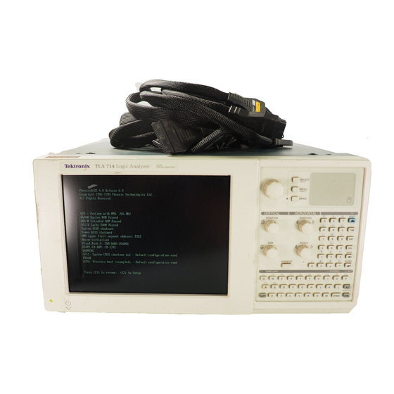
- Page 1 Tektronix TLA714 Manual Get Pricing & Availability at ApexWaves.com Call Today: 1-800-915-6216 Email: sales@apexwaves.com https://www.apexwaves.com/analyzers/tektronix-inc/tla700/TLA714...
-
Page 2: Service Manual
Service Manual TLA 714 Color Portable Mainframe 071-0267-01 Warning The servicing instructions are for use by qualified personnel only. To avoid personal injury, do not perform any servicing unless you are qualified to do so. Refer to all safety summaries prior to... - Page 3 Copyright © Tektronix, Inc. All rights reserved. Licensed software products are owned by Tektronix or its suppliers and are protected by United States copyright laws and international treaty provisions. Use, duplication, or disclosure by the Government is subject to restrictions as set forth in subparagraph (c)(1)(ii) of the Rights in Technical Data and Computer Software clause at DFARS 252.227-7013, or subparagraphs (c)(1) and (2) of the...
- Page 4 Tektronix, with shipping charges prepaid. Tektronix shall pay for the return of the product to Customer if the shipment is to a location within the country in which the Tektronix service center is located.
- Page 5 SOFTWARE WARRANTY Tektronix warrants that the media on which this software product is furnished and the encoding of the programs on the media will be free from defects in materials and workmanship for a period of three (3) months from the date of shipment.
-
Page 6: Table Of Contents
........... . 4–19 TLA 714 Color Portable Mainframe Service Manual... - Page 7 ........4–71 TLA 714 Color Portable Mainframe Service Manual...
- Page 8 ........7–3 Index TLA 714 Color Portable Mainframe Service Manual...
- Page 9 Figure 1–1: Front and side views of the portable mainframe ..1–10 Figure 2–1: TLA 714 portable mainframe front panel ... . 2–1 Figure 2–2: Portable mainframe rear panel .
- Page 10 Figure 7–5: Power supply and fan ......7–17 TLA 714 Color Portable Mainframe Service Manual...
- Page 11 ....... . . 1–7 Table 1–8: Certifications and compliances: TLA 714 Logic Analyzer Color Portable Mainframe .
-
Page 12: Portable Mainframe
Do Not Operate With Suspected Failures. If you suspect there is damage to this product, have it inspected by qualified service personnel. Do Not Operate in Wet/Damp Conditions. Do Not Operate in an Explosive Atmosphere. Keep Product Surfaces Clean and Dry. TLA 714 Color Portable Mainframe Service Manual... - Page 13 CAUTION indicates a hazard to property including the product. Symbols on the Product. The following symbols may appear on the product: WARNING Protective Ground CAUTION Double High Voltage (Earth) Terminal Refer to Manual Insulated viii TLA 714 Color Portable Mainframe Service Manual...
- Page 14 Use Care When Servicing With Power On. Dangerous voltages or currents may exist in this product. Disconnect power, remove battery (if applicable), and disconnect test leads before removing protective panels, soldering, or replacing components. To avoid electric shock, do not touch exposed connections. TLA 714 Color Portable Mainframe Service Manual...
- Page 15 Service Safety TLA 714 Color Portable Mainframe Service Manual...
- Page 16 Preface This is the service manual for the TLA 714 Color Portable Mainframe. Read this preface to learn how this manual is structured, what conventions it uses, and where you can find other information related to servicing this product. Read the Introduction following this preface for safety and other important background information needed before using this manual for servicing this product.
- Page 17 Preface Contacting Tektronix Product For questions about using Tektronix measurement products, call Support toll free in North America: 1-800-TEK-WIDE (1-800-835-9433 ext. 2400) 6:00 a.m. – 5:00 p.m. Pacific time Or contact us by e-mail: tm_app_supp@tek.com For product support outside of North America, contact your local Tektronix distributor or sales office.
- Page 18 H supports removal and replacement of those boards or assemblies H supports removal and replacement of the fuse, knobs, chassis, and other mechanical parts listed in the replaceable parts list This manual does not support component-level fault isolation and replacement. xiii TLA 714 Color Portable Mainframe Service Manual...
- Page 19 Warranty Repair Service Tektronix warrants this product for one year from date of purchase. The warranty is located behind the title page in this manual. Tektronix technicians provide warranty service at most Tektronix service locations worldwide. The Tektronix...
- Page 20 Specifications...
-
Page 22: Product Description
H Mainframe compatible with international power standards, certified to international safety and EMC requirements, and tested to rugged environ- mental standards 1–1 TLA 714 Color Portable Mainframe Service Manual... -
Page 23: Table 1-1: Internal Controller
Standard PC compatible IDE (Integrated device Electronics) 20X (minimum) CD ROM drive residing on an IDE interface. Continually subject to change due to the fast-moving PC component environment. Floppy Disk Drive Standard 3.5 inch 1.44-MB PC compatible high-density, double-sided floppy disk drive. 1–2 TLA 714 Color Portable Mainframe Service Manual... -
Page 24: Table 1-2: Display System
800 x 600 64,000 1024 x 768 1280 x 1024 1600 x 1200 Internal Display Classification TFT (Thin Film Transistor) active-matrix color LCD display, CCFL backlight, intensity controllable via software. Resolution 800 X 600 1–3 TLA 714 Color Portable Mainframe Service Manual... -
Page 25: Table 1-3: Backplane Interface
Vertically mounted glidepoint touchpad with three keypad control buttons (DRAG, SELECT, and MENU) Dual USB Ports Two USB complaint ports Mouse Port PS/2 compatible pointing device port Keyboard Port PS/2 compatible keyboard port 1–4 TLA 714 Color Portable Mainframe Service Manual... -
Page 26: Table 1-5: Rear Panel Interface
≤ 0.7 V sinking 10 mA Source Mode Falling edge sensitive Active Period Outputs system trigger state during valid acquisition period; resets system trigger output to false state and resets output latch between valid acquisitions via software 1–5 TLA 714 Color Portable Mainframe Service Manual... -
Page 27: Specifications
Intermodule Signal Line Bandwidth Minimum bandwidth over which the intermodule signals are specified to operate correctly: Signal 1,2 (ECLTRG0,1): 50 MHz square wave minimum Signals 3,4 (TTLTRG0,1): 10 MHz square wave minimum 1–6 TLA 714 Color Portable Mainframe Service Manual... -
Page 28: Table 1-6: Ac Power Source
–2 V –2.10 V –2.00 V –1.90 V –5.2 V –5.460 V –5.252 V –5.044 V –12 V –12.60 V –12.12 V –11.64 V –24 V –25.20 V –24.24 V –23.28 V 1–7 TLA 714 Color Portable Mainframe Service Manual... -
Page 29: Table 1-8: Certifications And Compliances: Tla 714 Logic Analyzer Color Portable Mainframe
Specifications Table 1–8: Certifications and compliances: TLA 714 Logic Analyzer Color Portable Mainframe EC Declaration of Conformity – EMC Meets intent of Directive 89/336/EEC for Electromagnetic Compatibility. Compliance was demonstrated to the following specifications as listed in the Official Journal of the European... -
Page 30: Table 1-9: Cooling
Half sine, 30 g, 11 ms duration, three drops each side, 9 shocks total, no media in floppy drive, Operating without instrument modules installed or with instrument modules installed but not exceeding 5 lbs/slot. Meets functional shock requirements of MIL-T-28800E, Type-III, Class 5 limited to top, bottom, face, or rear. 1–9 TLA 714 Color Portable Mainframe Service Manual... -
Page 31: Figure 1-1: Front And Side Views Of The Portable Mainframe
86 lbs 9 oz (39.26 kg) full configuration, with two TLA 7P4 modules and standard accessories (including probes) 17 in 17.5 in (43.18 cm) (44.45 cm) 9.25 in (23.5 cm) Figure 1–1: Front and side views of the portable mainframe 1–10 TLA 714 Color Portable Mainframe Service Manual... - Page 32 Operating Information...
-
Page 34: Figure 2-1: Tla 714 Portable Mainframe Front Panel
Figure 2–1 shows the front panel. Figure 2–2 shows the rear panel. Knobs Glidepoint Floppy disk CD–ROM drive Keyboard Front panel keyboard Mouse Replaceable hard disk drive Color display Figure 2–1: TLA 714 portable mainframe front panel 2–1 TLA 714 Color Portable Mainframe Service Manual... -
Page 35: Table 2-1: Usb (Universal Serial Bus) Pin Assignments
PS/2-compliant DIN connector. The keyboard port can be connected to an external, standard PS/2-compliant keyboard. PC Card Port There are two PCMCIA card slots that support an industry standard Type I, II, or III PCMCIA PC card. 2–2 TLA 714 Color Portable Mainframe Service Manual... -
Page 36: Figure 2-2: Portable Mainframe Rear Panel
Fixed Hard Disk Drive It is possible to add a fixed hard disk drive to the TLA 714 mainframe which is available through the TLA 7UP mainframe upgrade kit. Contact your Tektronix representative for more information on available upgrades to your mainframe. -
Page 37: Table 2-2: Svga Out Pin Assignments
15-pin, sub-D SVGA-compliant connector. See Table 2–2 for pin assignments. Table 2–2: SVGA OUT pin assignments Pin number Pin function Pin number Pin function (KEY) DDC DAT HSYNC VSYNC DDD CLK 2–4 TLA 714 Color Portable Mainframe Service Manual... -
Page 38: Table 2-3: Lpt (Parallel Interface) Pin Assignments
Table 2–3: LPT (parallel interface) pin assignments Pin number Pin function Pin number Pin function BUSY SLCT ACK* ERR* INIT* STB* SLIN* AFD* See IEEE specification P1284-C for pin connection definitions for other modes 2–5 TLA 714 Color Portable Mainframe Service Manual... -
Page 39: Operating System And Application Interface
The diagnostics window displays when any of the diagnostic tests fail. To access the diagnostics tests in the TLA 700 series application software, use the System pull-down menu. 2–6 TLA 714 Color Portable Mainframe Service Manual... - Page 40 Operating Information In addition to Power-on Diagnostics, the Portable Mainframe also contains mainframe diagnostics and QA+Win32 diagnostics for the PC hardware. For more information about diagnostics, refer to the Maintenance chapter. 2–7 TLA 714 Color Portable Mainframe Service Manual...
- Page 41 Operating Information 2–8 TLA 714 Color Portable Mainframe Service Manual...
- Page 42 Theory of Operation...
-
Page 44: Theory Of Operation
Mechanical Chassis The mechanical chassis provides the mechanical support structure for the instrument, and includes the cooling system, the modular-card cage, the EMI shielding system, and all the subsystems previously listed. 3–1 TLA 714 Color Portable Mainframe Service Manual... - Page 45 Theory of Operation 3–2 TLA 714 Color Portable Mainframe Service Manual...
- Page 46 Maintenance...
-
Page 48: Preparation
Do service of static-sensitive circuit boards only at a static-free work station. 4. Nothing capable of generating or holding a static charge should be allowed on the work station surface. 4–1 TLA 714 Color Portable Mainframe Service Manual... -
Page 49: Inspection And Cleaning
To confirm this, inspect the chassis for physical damage incurred during transit. Retain the chassis packaging in case shipment for repair is necessary. If there is damage or deficiency, contact your local Tektronix representative. Cleaning procedures consist of exterior and interior cleaning of the chassis. - Page 50 If the display is very dirty, moisten the wipe with distilled water or a 75% isopropyl alcohol solution and gently rub the display surface. Avoid using excess force or you may damage the plastic display surface. 4–3 TLA 714 Color Portable Mainframe Service Manual...
- Page 51 Maintenance 4–4 TLA 714 Color Portable Mainframe Service Manual...
-
Page 52: Removal And Installation Procedures
If you are removing a part for service, begin by looking up the procedure for that part. If any procedures are listed as required in advance in order to gain access to the part, perform those procedures first. 4–5 TLA 714 Color Portable Mainframe Service Manual... -
Page 53: Table 4-1: Tools Required For Part Removal
Table 4–1: Tools required for part removal Name Screwdriver with a T-15 Torx tip Screwdriver with a T-10 Torx tip Flat Blade Screwdriver Phillips screwdriver with a #1 tip Pliers Side cutters Scribe or jeweler’s screwdriver Cable ties 4–6 TLA 714 Color Portable Mainframe Service Manual... -
Page 54: Figure 4-1: External Parts
Chassis fan tray Cord-wrap feet Display assembly Trim ring Power supply Right side cover Bottom cover Front cover Front panel control assembly Replaceable CD–ROM Drive hard disk drive Figure 4–1: External parts 4–7 TLA 714 Color Portable Mainframe Service Manual... -
Page 55: Figure 4-2: Depress The Latch
The hard disk drive cartridge is removed by depressing it. This will release the latch. Pull on the removable hard disk drive to remove it from the chassis. Refer to Figure 4–3 and 4–4. Figure 4–2: Depress the latch 4–8 TLA 714 Color Portable Mainframe Service Manual... -
Page 56: Figure 4-3: Unlatching The Hard Disk Drive Cartridge
Removal and Installation Procedures Figure 4–3: Unlatching the hard disk drive cartridge Figure 4–4: Removing the hard disk drive cartridge 4–9 TLA 714 Color Portable Mainframe Service Manual... -
Page 57: Figure 4-5: Removing The Hard Disk Drive From The Cartridge
(Alternatively, you can use a flat-bladed screwdriver or other small prying tool to help you detach the snaps.) Then, swing the bottom of the ring upward and work the rest of the ring off the front panel. 4–10 TLA 714 Color Portable Mainframe Service Manual... -
Page 58: Figure 4-6: Trim Ring Removal
When removing the trim ring, grasp its bottom edge and flex it toward you before pulling upward. Trim ring Figure 4–6: Trim ring removal 4–11 TLA 714 Color Portable Mainframe Service Manual... -
Page 59: Flat Panel Display Assembly
4. Detach the cable connecting the flat panel display assembly to connector J209 on the front panel interface board. 5. Detach the five pin display backlight connector. 4–12 TLA 714 Color Portable Mainframe Service Manual... -
Page 60: Figure 4-7: Flat Panel Display Assembly Removal
(See Figure 4–7 on page 4–13). 4. Do the Trim Ring installation on page 4–11. 4–13 TLA 714 Color Portable Mainframe Service Manual... -
Page 61: Floppy Disk Drive
2. Do the Flat panel Display Assembly removal procedure, page 4–12. 3. Detach the ribbon cables at J100, J101, J209, J102, and J103. 4. Remove the one screw securing the interface board, and the two screws on the side panel. 4–14 TLA 714 Color Portable Mainframe Service Manual... -
Page 62: Front Panel Control Assembly
3. Remove the four screws that attach the front panel control assembly to the mainframe: two at the bottom of the assembly on the front of the instrument, two on the top. (See Figure 4–8 on page 4–16). 4–15 TLA 714 Color Portable Mainframe Service Manual... -
Page 63: Figure 4-8: Front-Panel Control Assembly Removal
CD ROM to the interface board. NOTE. Procedures for removing the knobs, elastomeric keypad, and Front Panel Control Board are found in Procedures for Internal Parts, which begins on page 4–33. 4–16 TLA 714 Color Portable Mainframe Service Manual... -
Page 64: Front Panel Knobs
To remove a front panel knob, grasp the knob and pull it straight out from the front panel. Installation To reinstall a knob, align the knob to a shaft and push in as far as it will go. 4–17 TLA 714 Color Portable Mainframe Service Manual... -
Page 65: Cd Rom Drive
3. Do the Front Panel Control Assembly install on page 4–17. 4. Do the Display Assembly installation procedure, page 4–13. 5. Do the Trim Ring installation on page 4–11. 4–18 TLA 714 Color Portable Mainframe Service Manual... -
Page 66: Bottom Cover
3. Lift bottom cover off. Installation Reposition the bottom cover on the bottom surface of the portable mainframe. Insert the four screws that attach the bottom cover to the mainframe. (See Figure 4–6 on page 4–11.) 4–19 TLA 714 Color Portable Mainframe Service Manual... -
Page 67: Top Cover
2. Insert the four screws that attach the top cover to the mainframe. (See Figure 4–9 on page 4–21.) 3. Do the Trim Ring installation procedure on page 4–10. 4. Reattach the accessories pouch to the top cover. (It snaps on.) 4–20 TLA 714 Color Portable Mainframe Service Manual... -
Page 68: Left Side Cover
2. Do the Top Cover removal procedure on page 4–20. 3. Loosen the two screws on the bottom cover closest to the left side of the mainframe. (See Figure 4–6 on page 4–11.) 4. Remove the left side cover. 4–21 TLA 714 Color Portable Mainframe Service Manual... -
Page 69: Right Side Cover
4. Tighten the two bottom cover screws nearest the right side of the mainframe. 5. Do the Top Cover installation procedure, page 4–20. 6. Do the Trim Ring installation procedure, page 4–10 7. Do the Line Cord and Line Fuse installation procedure, page 4–23. 4–22 TLA 714 Color Portable Mainframe Service Manual... -
Page 70: Line Cord And Line Fuse
3. Insert the line cord and retaining clamp into the mainframe side panel mounting hole, with the line cord oriented up and down. 4. Rotate the line cord 90 degrees counterclockwise. 5. Plug the line cord into its receptacle. 4–23 TLA 714 Color Portable Mainframe Service Manual... -
Page 71: Figure 4-10: Line Cord And Line Fuse Removal
Removal and Installation Procedures Pull Rotate Unplug Line fuse Fuse cap Figure 4–10: Line cord and line fuse removal 4–24 TLA 714 Color Portable Mainframe Service Manual... -
Page 72: Power Supply
2. Remove the four screws from the right side and the four screws from the bottom that secure the power supply to the chassis. 3. Pull on the handle to remove the power supply from the chassis. 4–25 TLA 714 Color Portable Mainframe Service Manual... -
Page 73: Rear Chassis Fan Tray
3. Grasp the left cord-wrap foot (facing the fan tray) and swing the left side of the fan tray away from the mainframe. 4. Disconnect the cable connecting the rear chassis fan tray to the backplane board. 5. Remove the rear chassis fan tray. 4–26 TLA 714 Color Portable Mainframe Service Manual... -
Page 74: Figure 4-12: Rear Chassis Fan Tray Removal
3. Reposition the rear chassis fan tray. 4. Reposition the cord-wrap feet (they snap into holes on the rear chassis fan tray), and insert the four screws that secure the rear chassis fan tray to the mainframe. 4–27 TLA 714 Color Portable Mainframe Service Manual... -
Page 75: Individual Fans
4. Use a pair of pliers to gently bend the metal tabs that hold the fan to the rear chassis fan tray until the fan is held firmly in position. 4–28 TLA 714 Color Portable Mainframe Service Manual... -
Page 76: Figure 4-13: Individual Fan Removal
5. Attach the hold-down bracket(s) to the rear chassis fan tray. 6. Do the Rear Chassis Fan Tray installation procedure, page 4–27. Screw Hold-down bracket Bend tabs Cable tie Latch Figure 4–13: Individual fan removal 4–29 TLA 714 Color Portable Mainframe Service Manual... -
Page 77: Flip Stands And Rear Feet
Flip stands Figure 4–14: Flip stand and rear feet removal Installation Reattach the flip stand or rear foot to the bottom cover. Do the Bottom Cover installation procedure as shown on page 4–19. 4–30 TLA 714 Color Portable Mainframe Service Manual... -
Page 78: Cord Wrap Feet
Installation Push the cord-wrap feet into the holes in the rear chassis fan tray to snap them into position. Do the Rear Chassis Fan Tray installation procedure as shown on page 4–27. 4–31 TLA 714 Color Portable Mainframe Service Manual... -
Page 79: Handle
Remove inner screws (2) Figure 4–16: Handle removal Installation Attach the handle and plastic handle mount to the power supply. Do the Right Side Cover installation procedure as shown on page 4–22. 4–32 TLA 714 Color Portable Mainframe Service Manual... -
Page 80: Procedures For Internal Parts
7. Remove the two screws securing the controller board to the chassis at the back panel. 8. Pull firmly on the rear panel until the controller board disconnects from the backplane board. 4–33 TLA 714 Color Portable Mainframe Service Manual... -
Page 81: Figure 4-17: Internal Parts
4. Reattach the three cables located near the bottom front corner of the controller board. 5. Reposition the EMI shield, and then insert the eight screws that secure it to the chassis. 4–34 TLA 714 Color Portable Mainframe Service Manual... -
Page 82: Main Memory
2. Reposition the EMI shield, and then insert the two screws that secure it to the chassis. 3. Do the Left Side Cover installation procedure, page 4–22. 4–35 TLA 714 Color Portable Mainframe Service Manual... -
Page 83: Backplane Board
Figure 4–18 on page 4–37. 2. Do the Front Panel Control Assembly removal procedure (page 4–15). 3. Remove the knobs from the front of the front panel control assembly. 4. Detach the glidepoint cable at J100. 4–36 TLA 714 Color Portable Mainframe Service Manual... -
Page 84: Figure 4-18: Front Panel Control Assembly Parts Locations
6. Gently use the prying tool in the slots on the top and bottom of the control assembly to work the control board free. 7. Lift the front panel control board out of the assembly. 4–37 TLA 714 Color Portable Mainframe Service Manual... -
Page 85: Glidepoint Assembly
1. Lay the glidepoint assembly face down on the work surface. 2. Do the Front Panel Control Assembly installation procedure on page 4–17. 3. Do the Trim Ring installation on page 4–11. 4–38 TLA 714 Color Portable Mainframe Service Manual... -
Page 86: Elastomeric Keypad
2. Do the Front Panel Control Board installation procedure. 3. Do the Front Panel Control Assembly installation procedure. 4. Do the Trim Ring installation on page 4–11. 4–39 TLA 714 Color Portable Mainframe Service Manual... - Page 87 Removal and Installation Procedures 4–40 TLA 714 Color Portable Mainframe Service Manual...
-
Page 88: Fixed Hard Disk Drive Removal And Installation
TLA 714 and TLA 720 Logic Analyzer Installation Manual. These instructions assume that you are familiar with servicing the instrument. Contact your nearest Tektronix, Inc., Service Center or Tektronix Factory Service Center for installation assistance. CAUTION. To prevent static discharge damage, service the instrument only in a static-free environment. -
Page 89: Preparation
You will need the following tools to perform this procedure: H Screwdriver with a T-15 Torx tip H Screwdriver with a T-10 Torx tip H Flat Blade Screwdriver H Phillips screwdriver with a #1 tip 4–42 TLA 714 Color Portable Mainframe Service Manual... -
Page 90: Remove Hard Disk Drive From The Cartridge
2. Carefully remove the hard disk drive from the cartridge, and remove the cable assembly from the connector on the hard disk drive. Remove 4 screws Figure 4–19: Removing the hard disk drive from the cartridge 4–43 TLA 714 Color Portable Mainframe Service Manual... -
Page 91: Removing The Replaceable Hard Disk Drive
The replaceable hard disk drive cartridge is removed by depressing it to release the latch. Pull on the replaceable hard disk drive cartridge to remove it from the chassis. Refer to Figure 4–20, 4–21 and 4–22. Figure 4–20: Depress the latch 4–44 TLA 714 Color Portable Mainframe Service Manual... -
Page 92: Figure 4-21: Unlatching The Hard Disk Drive Cartridge
Removal and Installation Procedures Figure 4–21: Unlatching the hard disk drive cartridge Figure 4–22: Removing the hard disk drive cartridge 4–45 TLA 714 Color Portable Mainframe Service Manual... -
Page 93: Remove The Trim Ring
When removing the trim ring, grasp its bottom edge and flex it toward you before pulling upward. Trim ring Figure 4–23: Front cover and trim ring removal 4–46 TLA 714 Color Portable Mainframe Service Manual... -
Page 94: Remove Flat Panel Display Assembly
2. Lift the bottom edge of the flat panel display assembly and rotate it upward and off the front face of the mainframe. 3. Detach the cable connecting the flat panel display assembly to connector J209 on the front panel interface board. 4–47 TLA 714 Color Portable Mainframe Service Manual... -
Page 95: Figure 4-24: Flat Panel Display Assembly Removal
Removal and Installation Procedures Remove screws (5) Flat panel display assembly Disconnect the cable Disconnect the cable Figure 4–24: Flat panel display assembly removal 4–48 TLA 714 Color Portable Mainframe Service Manual... -
Page 96: Install Fixed Hard Disk Drive
4. Attach the data cable to the fixed hard disk drive. 5. Position the fixed hard disk drive and attach the fixed hard disk drive to the bracket with the screws included with this kit as shown in figure 4–25. 4–49 TLA 714 Color Portable Mainframe Service Manual... -
Page 97: Figure 4-25: Installing The Fixed Hard Disk Drive
Screws (4) Slave Screws (4) jumper Figure 4–25: Installing the fixed hard disk drive 6. Do the Flat Panel Display Assembly procedure. 7. Do the Trim Ring Installation on page 4–51. 4–50 TLA 714 Color Portable Mainframe Service Manual... -
Page 98: Install Flat Panel Display Assembly
Turn off all other applications and close all open windows. b. Click Start → Programs → QA+Win32 c. Run the memory tests from the QA+Win32 menu. If needed, refer to the QA+Win32 online help for more information on running QA+Win32. 4–51 TLA 714 Color Portable Mainframe Service Manual... - Page 99 Removal and Installation Procedures 4–52 TLA 714 Color Portable Mainframe Service Manual...
-
Page 100: Troubleshooting
H Do Troubleshoot the Portable Mainframe, beginning on page 4–56, to locate the failed replaceable part within the mainframe. For assistance, contact your local Tektronix Service Center. Service Level This section supports isolation of faults within the portable mainframe to the replaceable-part level shown in Chapter 10. -
Page 101: Check For Common Problems
H Controller BIOS setup problem. See BIOS Settings. H Replaceable hard disk drive or optionally field installed fixed hard disk drive not configured as bootable (slave) master hard dsik drive. H Faulty benchtop controller. 4–54 TLA 714 Color Portable Mainframe Service Manual... - Page 102 H Faulty front panel interface board. H Module firmware incompatible with mainframe software Modules not recognized version. Refer to the TLA 714 and TLA 720 Installation Manual for software and module firmware update instructions. H TLA 700 system problem. Execute the internal resource manager program to determine if the mainframe recognizes any installed modules.
-
Page 103: Eliminate Other Problem Sources
BIOS errors. If you are unable to identify any problems through the troubleshooting tree or through the diagnostic programs refer to Isolating System Problems beginning on page 4–62 for further troubleshooting information. 4–56 TLA 714 Color Portable Mainframe Service Manual... -
Page 104: Figure 4-26: Primary Troubleshooting Tree
2 External monitor controls turned down 3 Defective monitor BIOS error See BIOS error message? code, Table 4–6 on page 4–65 Figure 4–26: Primary troubleshooting tree 4–57 TLA 714 Color Portable Mainframe Service Manual... -
Page 105: Controller And Pc Diagnostics
Group & test Power on Extended TLA 700 mainframe VTC Reset Test VTC Walk1 Test ADG Register Test ADG VXI Addr Test ADG VXI Data Test TLA 700 system Interrupt Lines Trigger Lines 4–58 TLA 714 Color Portable Mainframe Service Manual... -
Page 106: Qa+Win32
2. Click on Start in the Windows tool bar. 3. Select Programs from the Start menu. 4. Select Tektronix TLA 700 from the Programs menu. 5. Select TLA 700 Mainframe Diagnostics from the Tektronix TLA 700 menu. 4–59 TLA 714 Color Portable Mainframe Service Manual... -
Page 107: Bypassing Front Panel Controls
Measure the power supply voltages with the voltmeter and compare each reading to the values listed in the tables. If the voltages are within about 5% of the nominal voltages, your power supply is functional. 4–60 TLA 714 Color Portable Mainframe Service Manual... -
Page 108: Table 4-4: Power Supply Voltages And Backplane Connector Pins
–5.2 V +5 V Row B Row B +5 V +5 V +5 V Row C Row C +12 V –5.2 V +5 V –2 V –5.2 V +24 V –24 V 4–61 TLA 714 Color Portable Mainframe Service Manual... -
Page 109: Isolating System Problems
3 and 4, and try the tests again If the module works in the new location, you have identified a faulty slot in the mainframe. 4–62 TLA 714 Color Portable Mainframe Service Manual... -
Page 110: Table 4-5: Command Line Options For Resman32
H Faulty module. Replace the suspected faulty module with a known-good module, or contact your local Tektronix service center. H Incompatible module firmware and portable mainframe software versions. Refer to the TLA 700 Series Installation Manual for software and module firmware update instructions. -
Page 111: Figure 4-29: Resman32 Program Output
2: Asynchronous Enable succeeded **Responses are unsupported by this device Begin Normal Operation slot 1, LA 1, started successfully slot 3, LA 2, started successfully VISA Data la_1=1,1,4093,2036,2,0,1,7,2097152 la_2=2,3,4093,2033,2,0,1,7,2162688 Figure 4–29: ResMan32 program output 4–64 TLA 714 Color Portable Mainframe Service Manual... -
Page 112: Bios Setup Error Messages
Swap keyboard with a known good (Front panel keyboard. keypad error) Note: This error is quite uncommon because both the external keyboard and the front panel keypad would have to be missing or defective. 4–65 TLA 714 Color Portable Mainframe Service Manual... - Page 113 RAM/Calendar component. Note: After replacing the RAM/Calendar compo- nent, you must reflash the BIOS. Refer to Update the BIOS on page 4–67 and perform the procedures to reflash the BIOS. 4–66 TLA 714 Color Portable Mainframe Service Manual...
-
Page 114: Update The Bios Version
To update the BIOS, you will need the latest version of BIOS available on floppy disk. Refer to your TLA 714 and TLA 720 Installation Manual. Verify the BIOS Version The BIOS version is briefly displayed on boot up of the portable mainframe. -
Page 115: Adjustment After Repair
H Power-on diagnostics on the TLA 700 system. H Records the Pass/Fail status in the Calibration and Diagnostics property sheet. If no failures occur, the TLA 700 application is ready to use for regular tasks. 4–68 TLA 714 Color Portable Mainframe Service Manual... -
Page 116: Figure 4–30: Tla 700 Startup Sequence
Start TLA 700 application Start resource manager Module power-on diagnostics System controller TLA 700 system power-on diagnostics tests Records failures in Calibration and Diagnostic property sheet TLA 700 ready Figure 4–30: TLA 700 startup sequence 4–69 TLA 714 Color Portable Mainframe Service Manual... - Page 117 Troubleshooting 4–70 TLA 714 Color Portable Mainframe Service Manual...
-
Page 118: Repackaging Instructions
Packaging When repacking the portable mainframe for shipment, use the original packag- ing. If the packaging is unavailable or unfit for use, contact your local Tektronix representative to obtain new packaging. Seal the shipping carton with an industrial stapler or strapping tape. - Page 119 Repackaging Instructions 4–72 TLA 714 Color Portable Mainframe Service Manual...
- Page 120 Options...
-
Page 122: Mainframe
Tektronix sales representative. Tektronix Options Table 5–1 lists some of the options for the portable mainframe. These items are separately purchased and installed. Contact your local Tektronix representative for more information. Table 5–1: Portable Mainframe options and upgrade kits Description... -
Page 123: Service Options
And these options can be converted from service at Tektronix service depots to service on-site (see Option S1 and S3), which helps keep downtime to a minimum. -
Page 124: Table 5-2: Power Cord Identification
Table 5–2: Power cord identification Plug configuration Normal usage Option number North America Standard 125 V/15A Plug NEMA 5-15P Europe 230 V United Kingdom 230 V Australia 230 V North America 230 V Switzerland 230 V 5–3 TLA 714 Color Portable Mainframe Service Manual... - Page 125 Options 5–4 TLA 714 Color Portable Mainframe Service Manual...
- Page 126 Diagrams...
-
Page 128: Interconnection Block Diagram
W100 W400 Floppy hard disk drive disk drive J100 J101 J103 J102 W600 J101 Interface board Keypad J109 W500 W700 Color LCD Glidepoint display pointing device Figure 6–1: Portable mainframe interconnection diagram 6–1 TLA 714 Color Portable Mainframe Service Manual... -
Page 129: Figure 6–2: Portable Mainframe Block Diagram
External mouse, hard disk drive drive drive USB, and keyboard Backplane Fans TLA 700 Series module # 1 TLA 700 Series module # 2 Power supply Figure 6–2: Portable mainframe block diagram 6–2 TLA 714 Color Portable Mainframe Service Manual... - Page 130 Replaceable Mechanical Parts...
-
Page 132: Table 7-1: Standard Accessories
(for flashing module firmware) Power cord clip 343–1213–00 TLA 700 Series, Version 3.1, User Manual 071–0684–XX Tek mouse pad 016–1524–XX Cap, fuse holder 200–4326–00 Fuse, 15A 159–0256–00 Fuse, 6.3A 159–0381–00 Fuse, 20A 159–0379–00 7–1 TLA 714 Color Portable Mainframe Service Manual... -
Page 133: Table 7-2: Standard Accessories
070–9776–XX Technical Reference Parts Ordering Information Replacement parts are available through your local Tektronix field office or representative. Changes to Tektronix products are sometimes made to accommodate improved components as they become available and to give you the benefit of the latest improvements. -
Page 134: Using The Replaceable Parts List
670-7918-03 670-7918-XX When you order parts, Tektronix will provide you with the most current part for your product type, serial number, and modification (if applicable). At the time of your order, Tektronix will determine the part number revision level needed for your product, based on the information you provide. -
Page 135: Table 7-3: Parts Lists Column Descriptions
7733 TELEGRAPH RD MONTEBELLO, CA 90640–6537 PO BOX 750 7X318 KASO PLASTICS INC 5720–C NE 121ST AVE, STE 110 VANCOUVER, WA 98682 S5341 ALPS ELECTRIC CO LTD 1–7 YUKIGAYA–OHTSUKA–CHO OHTA–KU TOKYO JAPAN 7–4 TLA 714 Color Portable Mainframe Service Manual... - Page 136 747 WEST REDONDO BEACH; PO BOX 10 GARDENA, CA 90247-4203 S3109 FELLER U.S. CORPORATION 72 VERONICA AVE; UNIT #4 SOMERSET, NJ 08873 TK1163 POLYCAST INC 9898 SW TIGARD ST TIGARD, OR 97223 7–5 TLA 714 Color Portable Mainframe Service Manual...
- Page 137 312 EAST MAIN STREET WESTFIELD, PA 16950 80126 PACIFIC ELECTRICORD CO 747 WEST REDONDO BEACH GARDENA, CA 90247–4203 PO BOX 10 80009 TEKTRONIX INC 14150 SW KARL BRAUN DR BEAVERTON, OR 97077-0001 PO BOX 500 7–6 TLA 714 Color Portable Mainframe Service Manual...
- Page 138 Replaceable Mechanical Parts 7–7 TLA 714 Color Portable Mainframe Service Manual...
- Page 139 200–4279–00 COVER,FRONT:FRONT, PROTECTIVE, ABS, TEK BLUE 80009 200–4279–00 –11 214–4718–00 ACTUATOR,SWITCH:ACTUATOR,ON/STANDBY 80009 214–4718–00 –12 101–0149–00 TRIM,RING:FRONT TRIM RING,PLASTIC 80009 101–0149–00 –13 334–9634–00 MARKER,IDENT:LABEL, GE LEXAN,W/ADHESIVE 0KB05 334–9634–00 –14 200–4469–00 COVER:LEFT,PLASTIC 7X318 200–4469–00 7–8 TLA 714 Color Portable Mainframe Service Manual...
-
Page 140: Figure 7–1: External Parts
Replaceable Mechanical Parts Figure 7–1: External parts 7–9 TLA 714 Color Portable Mainframe Service Manual... - Page 141 KNOB,CAP:0.925 DIA,MACROBLEND DP4–1368 TK1163 366077000 –26 352–1063–00 OPTO, PASSIVE:LIGHT PIPE, 0.14 DIA X 1.445 INCHES 80009 352–1063–00 LONG, CLEAR ACRYLIC – 174–3520–00 CABLE ASSY,SP:FLAT FLEX,FLX,8,0.039 CTR,60.0 1DM20 174–3520–00 L,LAMINATED POLYESTER,3MM,EXPOSED CONDUCTOR BOTH 7–10 TLA 714 Color Portable Mainframe Service Manual...
-
Page 142: Figure 7–2: Front Panel Assembly
Replaceable Mechanical Parts Figure 7–2: Front panel assembly 7–11 TLA 714 Color Portable Mainframe Service Manual... - Page 143 BRACKET: FLOPPY DRIVE BRACKET 80009 407–4381–00 –11 119–5677–02 DISK DRIVE: FLOPPY, 3.5 INCH, 1.44MB, BLACK, 0.5 INCH 50356 FD–04HG–2600 HIGH, DSDD, FD–04HG–2600 –12 211–0895–00 SCREW,MACH:M2.6 X 0.45 X 8MM,PHILLIPS,PNH,ZINC 0KB01 211–0895–00 YELLOW 7–12 TLA 714 Color Portable Mainframe Service Manual...
-
Page 144: Figure 7–3: Floppy Disk Drive, Front Panel Interface Board, And Related Cables
Replaceable Mechanical Parts Figure 7–3: Floppy disk drive, front panel interface board, and related cables 7–13 TLA 714 Color Portable Mainframe Service Manual... - Page 145 IC,MEMORY:CMOS,SDRAM,8MEG X S5769 MC–458CD64S–A10 64,64M,SYNCHRONOUS,100MHZ,7NS,MODULE,MC–458CD6 4S–A10B,SODIMM14 –6 337–4191–00 SHIELD,ELEC:PROCESSOR,0.050 AL TK1943 337–4191–00 –7 012–0057–01 CA ASSY,RF:COAXIAL,RFD,50 OHM,43 060D9 012–0057–01 L,BNC,MALE,STR,BOTH ENDS,W/STRAIN RELIEF BOOT BOTH ENDS, –8 PART OF ITEM 3 REAR PANEL 7–14 TLA 714 Color Portable Mainframe Service Manual...
-
Page 146: Figure 7–4: Controller Board And Emi Shield
Replaceable Mechanical Parts Figure 7–4: Controller board and EMI shield 7–15 TLA 714 Color Portable Mainframe Service Manual... - Page 147 650–3591–01 PWR SUPPLY ASSY: HANDLE AND POWER SUPPLY 80009 650–3591–01 –16 020–2205–00 NUTBAR/SET SCREWS –17 378–0449–00 SHUTTER ASSY: INCLUDING FRAME, ACTUATOR, FIN, 7X318 2TEK1588 SPRING –18 131–6417–00 CONTACT, ELEC: GROUNDING TK2647 7701118003 7–16 TLA 714 Color Portable Mainframe Service Manual...
-
Page 148: Figure 7–5: Power Supply And Fan
Replaceable Mechanical Parts Figure 7–5: Power supply and fan 7–17 TLA 714 Color Portable Mainframe Service Manual... - Page 149 15–5P,W/CORD GRIP 161–0104–06 CA ASSY,PWR:3,1.0MM SQ,250V/10A,2.5 TK1373 ORDER BY METER,RTANG,IEC320,RCPT,EUROPEAN,SAFTEY DESCRIPTION CONTROLLED 161–0104–07 CA ASSY,PWR:3,1.0MM SQ,240V/10A,2.5 TK2541 ORDER BY METER,RTANG,IEC320,RCPT X 13A,FUSED,UK DESCRIPTION PLUG,(13A FUSE) 161–0104–05 CA ASSY,PWR:3,1.0MM SQ,250V/10A,2.5 TK1373 161–0104–05 METER,RTANG,IEC320,RCPT,AUSTRALIA,SAFTEY CONTROLLED 7–18 TLA 714 Color Portable Mainframe Service Manual...
- Page 150 PLUG(13A FUSE),UNI 161–0066–11 CA ASSY,PWR:3,1.0MM SQ,250V/10A,2.5 80126 ORDER BY METER,STR,IEC320,RCPT,AUSTRALIA DESCRIPTION 161–0066–12 CA ASSY,PWR:3,18 AWG,250V/10A,98 S3109 ORDER BY INCH,STR,IEC320,RCPT X NEMA 6–15P,US,SAFTEY DESCRIPTION CONTROLLED 161–0154–00 CA ASSY,PWR:3,1.0MM SQ,250V/10A,2.5 5F520 86515030 METER,STR,IEC320,RCPT,SWISS,SAFTEY CONTROLLED 7–19 TLA 714 Color Portable Mainframe Service Manual...
- Page 151 Replaceable Mechanical Parts 7–20 TLA 714 Color Portable Mainframe Service Manual...
- Page 152 Index...
- Page 154 Fixed hard disk drive, 2–3 Cover, bottom, removing and installing, 4–19 installing on TLA 714, 4–49 Cover, left side, installing, 4–22 Fixed hard disk drive assembly, TLA 714, 4–41 Cover, right side, installing, 4–22 Flat panel display Cover, top, removing and installing, 4–20 cleaning, 4–3...
- Page 155 2–3 removal for TLA 714, 4–44 floppy disk drive, 2–3 replaceable, 2–3 glide point device, 2–2 Hard disk drive assembly, TLA 714, 4–41 installation, 2–1 keyboard and knobs, 2–2 keyboard port, 2–2 LCD display, 2–2 LPT port, 2–5 I/O and memory hardware, 2–1...
- Page 156 PCMCIA port, 2–2 contacting Tektronix, xii Power cord for more information, xiv identification, 5–3 module repair and return, 7–3 installing, 4–23 module servicing, 7–3 options, 5–1 offerings, xiv Index–3 TLA 714 Color Portable Mainframe Service Manual...
- Page 157 3–1 warranty repair, xiv TLA 700 startup sequence, 4–68 world wide web address, xiv TLA 714 mainframe, removing the hard disk drive, Service safety summary, ix 4–44 Shipping instructions, 4–71 Tools required Side cover, left, removing, 4–21 to service, 4–6...
Need help?
Do you have a question about the TLA 714 and is the answer not in the manual?
Questions and answers