Nautilus Hyosung MX2600SE Service Manual
Hide thumbs
Also See for MX2600SE:
- Quick reference manual (2 pages) ,
- Installation manual (18 pages) ,
- Operator (268 pages)

Related Manuals for Nautilus Hyosung MX2600SE


Summary of Contents for Nautilus Hyosung MX2600SE
- Page 1 Service Manual MX2600SE System V01.00.00 (2015.03.09) © 2015 Nautilus Hyosung Inc. All Rights Reserved.
- Page 2 Version Date Description of Change Chapter V01.00.00 2015/03/09 New Publication © 2015 Nautilus Hyosung All Rights Reserved. The content of this specification is protected by copyright laws. 2015. 3. 9. 1st Release © 2015 Nautilus Hyosung Inc. All Rights Reserved.
-
Page 3: Table Of Contents
Troubleshooting ............................5-24 Optional Cash Dispenser Unit: CDU-M ...................... 5-25 Optional Cash Dispenser Unit: Drawer Type ....................5-53 Chapter6. Receipt Printer Overview ............................... 6-1 Repair and Maintenance ..........................6-5 Notes ............................Notes-1 © 2015 Nautilus Hyosung Inc. All Rights Reserved. - Page 4 What is in This Manual ............................1-1 Terminologies ............................... 1-2 Abbreviations ............................... 1-2 Safety Precautions (English) ..........................1-4 Précautions pour la sécurité (French) ......................... 1-6 Related Documents ............................. 1-8 Overview ................................1-9 Basic Features ..............................1-10 © 2015 Nautilus Hyosung Inc. All Rights Reserved. Chapter1-I...
-
Page 5: Chapter1. Preface
▶ This manual is produced to provide the MX2600SE maintenance guide for field technician. Audience ▶ This manual is for persons related to maintain MX2600SE in branches of banks, such as field technician and repair center engineer, to work efficiently and conveniently. Supported Information ▶... -
Page 6: Terminologies
Voice Converter for Visually Disabled Persons (ADA) Europay, Mastercard, Visa Elementary Program Encryption PIN Pad Hardware Interface International Standard Organization Journal Printer Liquid Crystal Display Magnetic Card Unit Operation Panel for Customers to Operate © 2015 Nautilus Hyosung Inc. All Rights Reserved. - Page 7 Power Supply Personal Identification Number Panel Control Board Printer (mainly Receipt Printer) Switch Sensor and Indications Unit Service Provider Slip Printer (Receipt Printer) Text Terminal Unit (OPL or SPL) Vacuum Fluorescent Display © 2015 Nautilus Hyosung Inc. All Rights Reserved.
-
Page 8: Safety Precautions (English)
▪ Do not touch the equipment when it is running. ▪ The equipment can get extremely hot and may cause a burn. ▪ Make sure to close the cover before running the equipment. © 2015 Nautilus Hyosung Inc. All Rights Reserved. - Page 9 TYPE. DISPOSED OF USED BATTERIES ACCORDING TO THE INSTRUCTIONS 3. FOR PLUGGABLE EQUIPMENT, THE SOCKET-OUTLET SHALL BE INSTALLED NEAR THE EQUIPMENT AN SHALL BE EASILY ACCESSIBLE 4. THE EQUIPMENT IS TO BE SECURED TO THE BUILDING STRUCTURE BEFORE OPERATION © 2015 Nautilus Hyosung Inc. All Rights Reserved.
-
Page 10: Précautions Pour La Sécurité (French)
• Ne pas retirer le couvercle. Seul le technicien d'entretien est autorisé à ouvrir le couvercle. • Ne pas toucher. Vous pouvez avoir un choc électrique. • Assurez-vous d'éteindre l'appareil lors de l'entretien de l'équipement. © 2015 Nautilus Hyosung Inc. All Rights Reserved. - Page 11 2. RISQUE D'EXPLOSION SI LA BATTERIE EST REMPLACEE PAR UN TYPE INCORRECT. DISPOSER POUR UTILISATION DES BATTRIES SELON LES INSTRUCTIONS 3. POUR LES APPAREILS RACCORDES, LA PRISE DOIT ETRE INSTALLEE PRES D’EQUIPEMENT POUR ÊTRE FACILEMENT ACCESSIBLE © 2015 Nautilus Hyosung Inc. All Rights Reserved.
-
Page 12: Related Documents
4. L’EQUIPEMENT DOIT ETRE SECURISE A LA STRUCTURE DU BATIMENT AVANT D'UTILISER Related Documents ▶ The related documents are listed as follows. If needed, please contact staffs of our technical support team and maintenance team. ▪ Operator Manual ▪ Installation Manual © 2015 Nautilus Hyosung Inc. All Rights Reserved. -
Page 13: Overview
Service Manual Chapter1. Preface Overview ► This manual is designed to provide maintenance guide for the MX2600SE ATM and provide detailed description of the following: ▪ System configuration ▪ Specification of each unit ▪ Facility specifications All information described in this manual is a licensed product of Nautilus Hyosung. -
Page 14: Basic Features
Chapter1. Preface Service Manual Basic Features ▶ Major features of MX2600SE are highlighted in the following list: Main Controller S5PC100 834MHz SDRAM 256MB Memory Flash 256MB Operating System WinCE 6.0 USB Ports USB 1.1 Port 1EA Option : Extended 4-... - Page 15 Battery Option <Note!> Your MX2600SE may not contain all the devices described in this section. Some devices are optional and some devices cannot be used in combination with other devices (mutually exclusive combinations). © 2015 Nautilus Hyosung Inc. All Rights Reserved.
- Page 16 Chapter 2 System Configuration Contents About the MX2600SE ............................2-1 The Exterior Overview ............................2-2 Hardware Configuration ............................2-3 © 2015 Nautilus Hyosung Inc. All Rights Reserved. Chapter2-I...
-
Page 17: About The Mx2600Se
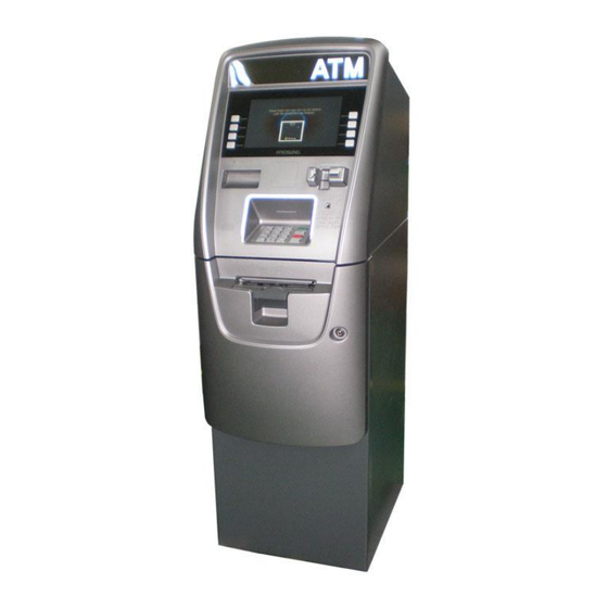
Service Manual Chapter2. System Configuration About the MX2600SE ► Newly designed ATM - The MX2600SE’s totally unique design enhances your customers’ ATM experience. Unlike any other retail ATM, the sleek look and halo-like LED lights will attract more users and drive additional transactions thus delivering more revenue to your bottom line. -
Page 18: The Exterior Overview
Chapter2. System Configuration Service Manual The Exterior Overview ▶ The following picture shows the front of MX2600SE and key units. The fascia provides the interface between the customer and MX2600SE. The customer selects transactions and requests information at the fascia. -
Page 19: Hardware Configuration
Service Manual Chapter2. System Configuration Hardware Configuration ► System Block Diagram © 2015 Nautilus Hyosung Inc. All Rights Reserved. - Page 20 Cortex Mainboard .............................. 3-18 Basic Specification............................3-18 CPU Block Diagram............................ 3-19 Board Block Diagram..........................3-20 Cortex-A8 M/B Layout ..........................3-20 Encryption PIN Pad ............................3-21 Common Occurred Problem List ........................ 3-22 Troubleshooting ............................3-22 © Nautilus Hyosung, Inc. All Rights Reserved. Chapter3-I...
-
Page 21: Chapter3. User Handling Unit
In case of contacting with hands, legs or clothes, it must be washed away thoroughly with soap. 8. Protect the module from static electricity, it may cause damage to the C-MOS Gate Array IC. © Nautilus Hyosung, Inc. All Rights Reserved. - Page 22 This can prevent the CMOS LSI chips from damage during latch-up. 3. The startup voltage of Backlight is approximately 1000 Volts. It may cause electrical shock while assembling with converter. Do not disassemble the module or insert anything into the Backlight unit. Nautilus Hyosung, Inc. All Rights Reserved.
-
Page 23: General Specifications
1. The specified power consumption (with converter efficiency) is under the conditions at VCCS = 3.3 V, fv = 60 Hz, LED_VCCS = Typ, fPWM = 200 Hz, Duty=100% and Ta = 25 ± 2 ºC, whereas mosaic pattern is displayed. © Nautilus Hyosung, Inc. All Rights Reserved. -
Page 24: Electrical Absolute Ratings
► Functional Block Diagram ► Interface Connections – PIN Assignment Symbol Description Remark No Connection (Reserve) VCCS Power Supply (3.3V typ.) VCCS Power Supply (3.3V typ.) VEDID DDC 3.3V power No Connection (Reserved for CMI test) Nautilus Hyosung, Inc. All Rights Reserved. - Page 25 Enable Control Signal of LED_EN LED Converter No Connection (Reserve) LED_VCCS LED Power Supply LED_VCCS LED Power Supply LED_VCCS LED Power Supply <Note!> The first pixel is odd as shown in the following figure. © Nautilus Hyosung, Inc. All Rights Reserved.
- Page 26 3) The specified power supply current is under the conditions at VCCS = 3.3 V, Ta = 25 ± 2 ºC, DC Current and fv = 60 Hz, whereas a power dissipation check pattern below is displayed. Nautilus Hyosung, Inc. All Rights Reserved.
- Page 27 RUSH ILED : the maximum current of the first 100ms after power-on, Measurement Conditions: Shown as the following figure. LED_VCCS = Typ, Ta = 25 ± 2 ºC, f = 200 Hz, Duty=100%. © Nautilus Hyosung, Inc. All Rights Reserved.
- Page 28 ≤ (N + 0.66) ∗ f (N ≥ 3) : Integer : Frame rate 4) The specified LED power supply current is under the conditions at “LED_VCCS = Typ.”, Ta = 25± 2 ºC, f = 200 Hz, Duty=100%. Nautilus Hyosung, Inc. All Rights Reserved.
- Page 29 4) The lifetime of LED is defined as the time when it continues to operate under the conditions at Ta = 25 ±2 C and I = 20 mA(Per EA) until the brightness becomes 50% of its ≦ s original value. © Nautilus Hyosung, Inc. All Rights Reserved.
- Page 30 Input Low Threshold =1.2V LVDS Common 1.125 1.375 Mode Voltage LVDS Differential Input Voltage LVDS Terminating Resistor <Note!> 1) The parameters of LVDS signals are defined as the following figures. 2. LVDS Data Format 3-10 Nautilus Hyosung, Inc. All Rights Reserved.
- Page 31 The higher the binary input the brighter the color. The table below provides the assignment of color versus data input. <Note!> 1) 0: Low Level Voltage, 1: High Level Voltage © Nautilus Hyosung, Inc. All Rights Reserved. 3-11...
- Page 32 The measurement methods of optical characteristics are shown in next table. The following items should be measured under the test conditions described in above table and stable environment shown in Note 5). 2. Optical Specifications <Note!> 1) Definition of Viewing Angle (θx, θy): 3-12 Nautilus Hyosung, Inc. All Rights Reserved.
- Page 33 The LCD module should be stabilized at given temperature for 20 minutes to avoid abrupt temperature change during measuring. In order to stabilize the luminance, the measurement should be executed after lighting Backlight for 20 minutes in a windless room. © Nautilus Hyosung, Inc. All Rights Reserved. 3-13...
- Page 34 Condition 1 : Contact Discharge, ±8KV Condition 2 : Air Discharge, ±15KV 220G, 2ms, half sine wave,1 time for each Shock (Non-Operating) direction of ±X,±Y,±Z Vibration (Non-Operating) 1.5G / 10-500 Hz, Sine wave, 30 3-14 Nautilus Hyosung, Inc. All Rights Reserved.
- Page 35 3) At testing Vibration and Shock, the fixture in holding the module has to be hard and rigid enough so that the module would not be twisted or bent by the fixture. © Nautilus Hyosung, Inc. All Rights Reserved. 3-15...
-
Page 36: Modem Board
- Over 6000 V Capacitive isolation - Parallel phone detect - Globally-compliant line interface 12. 27 MHz clock input 13. Single 3.3 V power supply 14. Firmware upgradeable 15. EEPROM interface 16. Pb-free, RoHS Compliant ► Block Diagram 3-16 Nautilus Hyosung, Inc. All Rights Reserved. - Page 37 Service Manual Chapter3. User Handling Unit ► Pin Assign +3V3 +3V3 CN24 LnRESET MODEM_nCD MODEM_nDSR M_SPKO(Sound Out) MODEM_nRTS MODEM_RXD MODEM_TXD CN25 MODEM_nRI MODEM_nDTR MODEM_nCTS © Nautilus Hyosung, Inc. All Rights Reserved. 3-17...
-
Page 38: Cortex Mainboard
2 Ports 2.0 Device 1 Port SD Card MODEM 1 Port Interface 1 Port (supported through I/O RGB 16bit Board) HDMI LVDS AC97 1 EA GPIO 4 bit 1 Port I2C I/F Vibration motor 3-18 Nautilus Hyosung, Inc. All Rights Reserved. -
Page 39: Cpu Block Diagram
Service Manual Chapter3. User Handling Unit Camera I/F ITU R BT-656 Dimension Dimension 100 X 75 CPU Block Diagram ► CPU Block Diagram © Nautilus Hyosung, Inc. All Rights Reserved. 3-19... -
Page 40: Board Block Diagram
Chapter3. User Handling Unit Service Manual Board Block Diagram ► Board Block Diagram Cortex-A8 M/B Layout ► Cortex-A8 M/B Layout 3-20 Nautilus Hyosung, Inc. All Rights Reserved. -
Page 41: Encryption Pin Pad
Serial Communication during OFF USB/Serial OPEN Boot firmware download is Common for available for CLOSE. USB/Serial Power Connector Common for USB/Serial Serial Connector Common for USB/Serial CN10 USB Connector Common for USB/Serial © Nautilus Hyosung, Inc. All Rights Reserved. 3-21... -
Page 42: Common Occurred Problem List
1. If LED1 is off, check the cable connection to see if the power supply is okay. 2. If LED1 is on and LED2 is off, it means EPP is in abnormal operation. Therefore, replace the EPP 3-22 Nautilus Hyosung, Inc. All Rights Reserved. - Page 43 Short Circuit Protection ..........................4-5 Environmental Requirement ..........................4-6 Temperature Range ............................4-6 Humidity ................................ 4-6 Vibration ................................ 4-6 Ground Leakage Current ..........................4-6 Reliability ..............................4-6 Dielectric Strength ............................4-7 Insulation Resistance ........................... 4-7 © 2015 Nautilus Hyosung Inc. All Rights Reserved. Chapter4-I...
-
Page 44: Chapter4. Power Supply
1. Open the upper front door 2. Press the power switch (“O”) 3. The system will be shut down automatically 4. The operating system will shut down then power will turn off. © 2015 Nautilus Hyosung Inc. All Rights Reserved. -
Page 45: General Description And Scope
Input Line Current & Power Factor (P.F.) ► At Full load AC input Input line current P.F.@ Full Load P.F.@ Pin=75W < 1.5Amps –rms 110V > 0.95 > 0.9 < 1Amps –rms 220V > 0.9 > 0.85 © 2015 Nautilus Hyosung Inc. All Rights Reserved. -
Page 46: Output Electrical Requirements
10 uF electrolytic capacitor across the measuring terminals. 3. RIPPLE & NOISE test condition : Bandwidth 20MHz 4. +24V PEAK LOAD time does not exceed 0.5mS © 2015 Nautilus Hyosung Inc. All Rights Reserved. -
Page 47: Load Capacity Specifications
+24VLOAD FOR TESTTEMPERATURE (+12V & +5V @Fullload of “Loading Table for Efficiency Measurements” ) ► +24VLOAD FOR TESTTEMPERATURE (+12V & +5V @Fullload of “Loading Table for Efficiency Measurements”) Signal Specification (@Fullload of “Loading Table for Efficiency Measurements”) © 2015 Nautilus Hyosung Inc. All Rights Reserved. -
Page 48: Apply Extra Outlet
The power supply shall return to normal operation after the short circuit has been removed and the power switch has been turned off for no more than 5 seconds. © 2015 Nautilus Hyosung Inc. All Rights Reserved. -
Page 49: Environmental Requirement
► The power supply ground leakage current shall be less than 3.5mA. Reliability ► The power supply reliability, when calculated by MIL-HDBK-217;latest revision, are exceed 300,000 hours with all output at Typical load and an ambient temperature of 25℃. © 2015 Nautilus Hyosung Inc. All Rights Reserved. -
Page 50: Dielectric Strength
PRI -F.G AC 1800V Insulation Resistance Division Test Point Test Input Voltage Test Condition PRI –SEC DC 500V During Of Test: Insulation 1 minute Resistance PRI -F.G DC 500V Insulation RES: ≥10Mohm © 2015 Nautilus Hyosung Inc. All Rights Reserved. - Page 51 Cable Connection Diagram ........................5-52 Optional Cash Dispenser Unit: Drawer Type ..................... 5-53 Sensor Replacement ..........................5-53 Module Replacement ..........................5-58 Adjustment Standard ..........................5-64 Oiling Standard ............................5-65 Cleaning Standard ............................5-66 © 2015 Nautilus Hyosung Inc. All Rights Reserved. Chapter5-I...
-
Page 52: Overview
Service Manual Chapter5. Cash Dispenser Unit Overview ► Appearance & Dimension © 2015 Nautilus Hyosung Inc. All Rights Reserved. - Page 53 Admit up to 1,000 sheets and contain the separation section Cassette Section (partial roller structure of overlap method). After checking the length, interval, skew, and thickness of the Reject Section separated notes, keep the N.G notes. © 2015 Nautilus Hyosung Inc. All Rights Reserved.
- Page 54 Friction Type Based on Capacity 200sheets new notes Reject Security No Key Quantity Software Detection Count Based on Capacity 1,000sheets new notes Front Access Cassette Loading Direction Front Access Type Detecting Remnants © 2015 Nautilus Hyosung Inc. All Rights Reserved.
-
Page 55: Disassembly & Reassembly
5. Remove 2 screws (⑦) and disassemble ASSY PULLEY_ID (⑧). 6. Remove 2 screws (⑨) and disassemble ASSY PULLEY_DR (⑩). 7. Remove 1 screw (⑪) and disassemble GEAR Z36W08M10_DR (⑫). 8. Disassemble ASSY GEAR Z28W09M10_ID (⑬). © 2015 Nautilus Hyosung Inc. All Rights Reserved. - Page 56 9. Remove 4 screws (⑭) and disassemble Double Bill Detection Section (⑮). 10. To assemble again, use the reverse order of disassembling. <Note!> Be sure to insert the belt during assembling ASSY PULLEY and Double Bill Detection Section. © 2015 Nautilus Hyosung Inc. All Rights Reserved.
-
Page 57: Electronic Parts Disassembly
Chapter5. Cash Dispenser Unit Service Manual Electronic Parts Disassembly Sensor Disassembly ► Location Map of Sensor © 2015 Nautilus Hyosung Inc. All Rights Reserved. - Page 58 4. Remove 2 screws (①) and disassemble holder (⑤) / sensor (③) /sensor (④). 5. To assemble again, use the reverse order of disassembling. <Note!> Be sure to check the position of sensor and assemble it. (Refer to figure below) © 2015 Nautilus Hyosung Inc. All Rights Reserved.
- Page 59 4. Remove 2 screws (①) and disassemble holder (⑤) to disassemble sensor (③) and sensor (④) 5. To assemble again, use the reverse order of disassembling. <Note!> Be sure to check the position of sensor and assemble it. © 2015 Nautilus Hyosung Inc. All Rights Reserved.
- Page 60 2. Disassemble sensor (2ea, ①) of ASSY MOLD LOWER DOWN. 3. Disassemble cable connector (CS1_A,CS1_B) of SENSOR. 4. To assemble again, use the reverse order of disassembling. <Note!> Be careful for the direction of cable (CS1_A,CS1_B). © 2015 Nautilus Hyosung Inc. All Rights Reserved.
- Page 61 3. Disassemble sensor (2ea, ②) as shown in figure. 4. Disassemble the cable connector (CS1_A,CS1_B) of sensor . 5. To assemble again, use the reverse order of disassembling. <Note!> Be careful for the direction of the cable (CS1_A, CS1_B). 5-10 © 2015 Nautilus Hyosung Inc. All Rights Reserved.
- Page 62 4. Remove a screw (CS8: ③) and disassemble encoder. Then disassemble the sensor (②) on section B pressing it in the direction of arrow. 5. To assemble again, use the reverse order of disassembling. © 2015 Nautilus Hyosung Inc. All Rights Reserved. 5-11...
-
Page 63: Motor Disassembly
1. After disassembling cable (M1) on section A, remove 3 screws (①) and disassemble Assy Motor (②) 2. Disassemble GEAR (③) and E-RING (④) from Assy Motor. 3. To assemble again, use the reverse order of disassembly. 5-12 © 2015 Nautilus Hyosung Inc. All Rights Reserved. -
Page 64: Solenoid Disassembly
1. Remove 2 screws (①) and disassemble the main cover (②) 2. Disassemble the cable (SOL1) on section A. 3. Disassemble e-ring (③) connected to solenoid and bracket. Then disassemble Assy Solenoid. © 2015 Nautilus Hyosung Inc. All Rights Reserved. 5-13... - Page 65 Chapter5. Cash Dispenser Unit Service Manual 4. Disassemble the solenoid from Solenoid Assy. 5. To assemble again, use the reverse order of disassembly. <Note!> Be careful not to miss the rubber damper. 5-14 © 2015 Nautilus Hyosung Inc. All Rights Reserved.
-
Page 66: Clutch Disassembly
4. Disassemble ASSY GEAR (③). 5. Remove a screw (④) and disassemble Assy Clutch in the direction of arrow. <Note!> Be careful not to damage section A of above figure during disassembling. © 2015 Nautilus Hyosung Inc. All Rights Reserved. 5-15... - Page 67 6. Unfasten the Set Screw as shown in figure (⑤) and disassemble the clutch. (Please use the hexagon wrench during disassembling.) 7. To assemble again, use the reverse order of disassembling. <Note!> Apply the Loctite 242 on the screw thread before assembling Set Screw. 5-16 © 2015 Nautilus Hyosung Inc. All Rights Reserved.
-
Page 68: Pcba Disassembly
3. Remove 2 screws (③) and disassemble PCBA. <Note!> Be careful not to damage Section A on the upper part when detaching PCBA. 4. To assemble again, use the reverse order of disassembly. © 2015 Nautilus Hyosung Inc. All Rights Reserved. 5-17... -
Page 69: Preventive Maintenance
<Note!> Grease 0.1g is equivalent to about 1.2mm squeezed by grease gun whose inlet is 7mm in diameter. 3. The type of lubricant Type Name Remark Grease(G1) G-501 (White) Grease(G2) ALVANIA EP#1 (Yellow) 5-18 © 2015 Nautilus Hyosung Inc. All Rights Reserved. -
Page 70: Lubrication Standard For Each Part
Chapter5. Cash Dispenser Unit Lubrication Standard for each part ► Lubrication Standard for each part Part Description Point Type SPRING:GATE_SOLENOID 1 place SPRING:CO-OD35ID45N15 4 places K-ASSY:FRAME_L 1 place K-ASSY:FRAME_R 1 place © 2015 Nautilus Hyosung Inc. All Rights Reserved. 5-19... -
Page 71: Cleaning (Inspection)
(4~6 times a round-trip of brush) 2. Remove the foreign substance from the prism surface of separated transmissive sensor (CS1,CS13,CS4) with a cotton swab. Cleaning Cleaning Cleaning Method Remark Point Cycle Prism Cotton Swab 5-20 © 2015 Nautilus Hyosung Inc. All Rights Reserved. - Page 72 1. Remove the foreign substances from the double bill detection lever with a air brush. Cleaning Cleaning Cleaning Point Remark Cycle Method Double Bill Detection Section of the AIR BRUSH Transport Path © 2015 Nautilus Hyosung Inc. All Rights Reserved. 5-21...
-
Page 73: Parts Replacement
Parts Replacement Required Tools for Replacement ► Required Tools Name of Tool Picture + Driver - Driver Number 1.5 + Driver E-LING CLIP LONG NOSE Spring Hook or Pincette Hexagon Wrench 5-22 © 2015 Nautilus Hyosung Inc. All Rights Reserved. -
Page 74: How To Replace
► Mounting Catch [Section B] in case of Cassette Catch Damage 1. Unfasten a screw (M2.5X8) in case of damage and remove the damaged Catch. Then replace it with new one. © 2015 Nautilus Hyosung Inc. All Rights Reserved. 5-23... -
Page 75: Troubleshooting
Chapter5. Cash Dispenser Unit Service Manual .Troubleshooting ► How to remove a jam Take out the jammed note pulling the belt as shown in below picture. 5-24 © 2015 Nautilus Hyosung Inc. All Rights Reserved. -
Page 76: Optional Cash Dispenser Unit: Cdu-M
Chapter5. Cash Dispenser Unit Optional Cash Dispenser Unit: CDU-M Appearance/Functional Diagram ► The following figures show the three sectional diagrams of the CDU. CDU is 623.00mm (24.53inch) high and 303.00 mm (11.93inch) wide. © 2015 Nautilus Hyosung Inc. All Rights Reserved. 5-25... -
Page 77: Cassette
Chapter5. Cash Dispenser Unit Service Manual Cassette ► The following figures show three sectional diagrams of the cassette. Cassette is 137.50mm (5.41inch) high, 217.00mm (8.54inch) wide and 342mm (13.46inch) long. 5-26 © 2015 Nautilus Hyosung Inc. All Rights Reserved. -
Page 78: Actuator Diagram
Service Manual Chapter5. Cash Dispenser Unit Actuator Diagram ► Six actuators are used. The following figure shows their location. GATE SOLENOID 2 MAIN MOTOR GATE SOLENOID 1 RJ BIN CASSETTE#1 CASSETTE#2 CASSETTE#3 © 2015 Nautilus Hyosung Inc. All Rights Reserved. 5-27... -
Page 79: Sensor Diagram
► The following figure shows the location of 29 sensors in this system. <Note!> A = Sensor far from the board. B = Sensor close to the board. Front View 정면도 5-28 © 2015 Nautilus Hyosung Inc. All Rights Reserved. -
Page 80: Module And Sensor Replacement
The CDU contains a total of 28 sensors including 20 returning path sensors, 1 gate operation detection sensor, 3 cassette position detection sensors, 3 remaining note detection sensors and 1 encoder sensor. © 2015 Nautilus Hyosung Inc. All Rights Reserved. 5-29... - Page 81 4. From the removed sensor bracket, remove the M3 sensor screws (1 place each) of the sensor which will be replaced. 5. Replace the sensor. 6. Assemble the unit in the reverse order - 4~1. 5-30 © 2015 Nautilus Hyosung Inc. All Rights Reserved.
- Page 82 4. From the removed sensor bracket, remove the M3 sensor screws (1 place each) of the sensor which will be replaced. 5. Replace the sensor. 6. Assemble the unit in the reverse order - 4~2. © 2015 Nautilus Hyosung Inc. All Rights Reserved. 5-31...
- Page 83 6. Assemble the unit in the reverse order - ④~①. Make sure to fasten the spacer and the screw end is not protruding out to the other side of the bracket. 5-32 © 2015 Nautilus Hyosung Inc. All Rights Reserved.
- Page 84 3. Remove the sensor bracket. 4. Remove the M3 sensor fastening screws from the removed sensor bracket. 5. Replace the sensor. 6. Assemble the unit in the reverse order - 4~1. © 2015 Nautilus Hyosung Inc. All Rights Reserved. 5-33...
- Page 85 6. Assemble the unit in the reverse order - 4~1. Make sure to fasten the spacer and the screw end is not protruding out to the other side of the bracket. 5-34 © 2015 Nautilus Hyosung Inc. All Rights Reserved.
- Page 86 4. Remove the M3 sensor fastening screws of the sensor to replace from the removed sensor bracket. 5. Replace the sensor. 6. Assemble the unit in the reverse order - 4~1. © 2015 Nautilus Hyosung Inc. All Rights Reserved. 5-35...
- Page 87 6. Assemble the unit in the reverse order - 4~1. Make sure to fasten the spacer and the screw end is not protruding out to the other side of the bracket. 5-36 © 2015 Nautilus Hyosung Inc. All Rights Reserved.
- Page 88 6. Assemble the unit in the reverse order - 4~1. Make sure to fasten the spacer and the screw end is not protruding out to the other side of the bracket. © 2015 Nautilus Hyosung Inc. All Rights Reserved. 5-37...
- Page 89 5. Assemble in the reverse order - 3~1. <Note!> When reassembling the CS3, pull the solenoid and adjust the detection bracket to the center of the sensor while the screw is still loose. Then, tighten the screw. 5-38 © 2015 Nautilus Hyosung Inc. All Rights Reserved.
- Page 90 4. To insert the sensor, insert the part ① first, then press part ② to lock. 5. Assemble in the reverse order - 3~1. <Note!> Make sure that the sensor always faces towards the center of the encoder shaft as shown in the following figure. © 2015 Nautilus Hyosung Inc. All Rights Reserved. 5-39...
- Page 91 4. Remove the MP3 sensor screws (2 places each) from the removed sensor bracket. 5. Replace the sensor. 6. Assemble the unit in the reverse order - 4~1. <Note!> Adjust the cassette position when mounting it until a click sound is heard. 5-40 © 2015 Nautilus Hyosung Inc. All Rights Reserved.
- Page 92 <Note!> Adjust the sensor by running the variable resistance so that it generates a current below 1.0V if there is cash available and above 3.0V if no cash is available. © 2015 Nautilus Hyosung Inc. All Rights Reserved. 5-41...
-
Page 93: Module Replacement
3. Remove the board M3 screws (4 places in the main board, 8 places in the FM board (6 screws, 2 jack posts) and 2 places in the DC board). 4. Replace the board. 5. Assemble in the reverse order – 4 ~ 1. 5-42 © 2015 Nautilus Hyosung Inc. All Rights Reserved. - Page 94 2. Remove the power cable from the main motor. 3. Unscrew the main motor fixing screws (M5, 4 places). 4. Remove the main motor assembly and replace it. 5. Assemble in the reverse order – 4 ~ 1. © 2015 Nautilus Hyosung Inc. All Rights Reserved. 5-43...
- Page 95 3. Unscrew the solenoid bracket screws (M4, 2 places). 4. Unscrew the solenoid fixing screws (M4, 4 places). 5. Assemble in the reverse order – 4 ~1 after replacing a solenoid assembly. Adjust the gate according to the standard. 5-44 © 2015 Nautilus Hyosung Inc. All Rights Reserved.
- Page 96 2. Remove the M4 screw (1 pace) and E-Ring to remove the clutch as shown in the above figure. Then, remove the M4 screws (3 places) as shown in the figure below. © 2015 Nautilus Hyosung Inc. All Rights Reserved. 5-45...
- Page 97 When replacing the clutch assembly, adjust the tension pulley so that belt tension is about 100g to the direction and about 200g ~ 300g to the direction when the timing belt is pressed by about 3mm (use the tension gauge). 5-46 © 2015 Nautilus Hyosung Inc. All Rights Reserved.
-
Page 98: Adjustment Standard
M3 STOP SCREW GATE SOLENOID ADJUSTMENT GATE BRACKET When the gate is pulled When the gate is released GATE를 당겼을 때 GATE를 놓았을 때 4. Fix the solenoid M4 screws (2 places). © 2015 Nautilus Hyosung Inc. All Rights Reserved. 5-47... - Page 99 <When Solenoid is Pulled> When the gate 2 is CS2T SENSOR GATE2 (놓았을 때) SUPPORTER released When the gate 2 is pulled GATE2 (당겼을 때) Over 3mm BELT SUPPORTER < When Solenoid is Released> 5-48 © 2015 Nautilus Hyosung Inc. All Rights Reserved.
-
Page 100: Oiling Standard
Note separate Initial assembly gear Albania Grease EP1 Oiling teeth surface GATE BUSH GATE SPRING HOOK TENSION PULLEY GEAR SUPPORT SPRING HOOK NOTE SEPARATE ASSEMBLY GEAR TEETH SURFACE GEAR TEETH SURFACE © 2015 Nautilus Hyosung Inc. All Rights Reserved. 5-49... -
Page 101: Cleaning Standard
CS3 / CS8 soft brush CS7 / CS7 / CS17 CS6 / CS16 / CS26 Guide entrance Remove the foreign Note separate Roller objects and dust using a ASS’Y soft brush 5-50 © 2015 Nautilus Hyosung Inc. All Rights Reserved. -
Page 102: Setting Specifications
3. FM B/D DIP S/W Specifications FM B/D DIP S/W Remark 2 CASSETTE #1, #6, #7 : ON Default 3 CASSETTE #2, #4, #6 : ON Default (Mounting 2 Cassettes) (Mounting 3 Cassettes) © 2015 Nautilus Hyosung Inc. All Rights Reserved. 5-51... -
Page 103: Cable Connection Diagram
Sensor Unit Motor, Clutch, Solenoid Additional Sensor Unit RS-232C Comm. PLD Download POWER (VCC, +12V, +24V, GND) DIP S/W signal DC/DC Power Unit CN10 FM B/D Connection Unit CN12 2 Sheet I/F 5-52 © 2015 Nautilus Hyosung Inc. All Rights Reserved. -
Page 104: Optional Cash Dispenser Unit: Drawer Type
1 cassette position detection sensors, 1 encoder sensor and 2 remaining cash detection sensors . The following figure shows the position of each sensor. Remove the CDU cover as shown in the figure to replace sensors. © 2015 Nautilus Hyosung Inc. All Rights Reserved. 5-53... - Page 105 4) From the removed sensor bracket, remove the M3 sensor screws (1 place each) of the sensor which will be replaced. 5) Replace the sensor. 6) Assemble the unit in the reverse order – 4) ~ 1). 5-54 © 2015 Nautilus Hyosung Inc. All Rights Reserved.
- Page 106 Service Manual Chapter5. Cash Dispenser Unit © 2015 Nautilus Hyosung Inc. All Rights Reserved. 5-55...
- Page 107 6) When reassembling the LS7 & LS8, pull the solenoid and adjust the detection bracket to the center of the sensor while the screw is still loose. Then, tighten the screw. 5-56 © 2015 Nautilus Hyosung Inc. All Rights Reserved.
- Page 108 3) Remove the sensor bracket. 4) Remove the M3 sensor screws (2 places each) from the removed sensor bracket. 5) Replace the sensor. 6) Assemble the unit in the reverse order – 4) ~ 1). © 2015 Nautilus Hyosung Inc. All Rights Reserved. 5-57...
-
Page 109: Module Replacement
3) Remove the connector from the board. Be careful not to break the connector pin. 4) Remove the board M3 screws (5 places). 5) Replace the board. 6) Assemble in the reverse order – 4) ~ 1) 5-58 © 2015 Nautilus Hyosung Inc. All Rights Reserved. - Page 110 4) Remove the main motor assembly and replace it. 5) Assemble in the reverse order – 4) ~ 1) Be careful to adjust the gap of Main motor gear and Main board gear. © 2015 Nautilus Hyosung Inc. All Rights Reserved. 5-59...
- Page 111 6) Remove the solenoid spring. 7) Remove the solenoid M3 screws (2 places). 8) After replacing solenoid assembly, assemble in the reverse order – 7) ~ 1). Adjust the gate according to the standard. 5-60 © 2015 Nautilus Hyosung Inc. All Rights Reserved.
- Page 112 4) Remove the note separate motor assembly and replace it. 5) Assemble in the reverse order – 4) ~ 1). Be careful to adjust the gap of the note separate motor gear and note separate ASS’Y gear. © 2015 Nautilus Hyosung Inc. All Rights Reserved. 5-61...
- Page 113 4) Remove the double detect lever assembly upward. 5) Replace the double detect lever assembly and assemble in the reverse order – 4) ~ 1). 6) Check the lever to operate well. 7) Take the test. 5-62 © 2015 Nautilus Hyosung Inc. All Rights Reserved.
- Page 114 2) Remove the note separate assembly M3 screws (6 places). 3) Remove the note separate assembly from the main body and replace it. 4) Assembly in the reverse order – 3) ~ 1) © 2015 Nautilus Hyosung Inc. All Rights Reserved. 5-63...
-
Page 115: Adjustment Standard
3) After adjusting the position of the gate, adjust the location of the sensor by moving the sensor bracket in a way that the solenoid adjustment bracket passes the center of LS7 sensor when the solenoidis on. Then, fix the location of the sensor. 5-64 © 2015 Nautilus Hyosung Inc. All Rights Reserved. -
Page 116: Oiling Standard
Gear teeth Mobil (1) surface Gear teeth Mobil (1) surface * Y1 : Y1: Once a year. *: Warning: Be careful not to contaminate the belt with lubricant © 2015 Nautilus Hyosung Inc. All Rights Reserved. 5-65... -
Page 117: Cleaning Standard
Note separate Remove the foreign objects and dust Roller ASS’Y using the soft brush * M6 : Once every 6 months Y1 : Once a year 5-66 © 2015 Nautilus Hyosung Inc. All Rights Reserved. - Page 118 DIP S/W SETTING ............................6-4 Repair and Maintenance ............................6-5 Replacing the End Sensor ..........................6-5 Replacing the Jam Sensor ........................... 6-8 Replacing the Motor ........................... 6-10 Replacing TPH (ATP-82K) .......................... 6-11 Oiling ................................6-13 © 2015 Nautilus Hyosung Inc. All Rights Reserved. Chapter6-I...
-
Page 119: Chapter6. Receipt Printer
Outlet Assembly. Outlet Assembly has a short transport section which enables portrait printing. It is also easy to maintain or repair in case of receipt jams because of its open structure © 2015 Nautilus Hyosung Inc. All Rights Reserved. -
Page 120: Appearance And Dimension
Chapter6. Receipt Printer Service Manual Appearance and Dimension ▶ Appearance and Dimension © 2015 Nautilus Hyosung Inc. All Rights Reserved. -
Page 121: Arrangement Plan
Default: Off Paper Internal Returning Returns the paper Default: Off Motor Motor Motor of Cutter Motor Drives the cutter Nautilus Default: Off Hyosung Paper Returning Returns the paper PM20S Default: Off Motor © 2015 Nautilus Hyosung Inc. All Rights Reserved. -
Page 122: Basic Specifications
/ Humidity: 10 ~ 80% Rate 100mm/s Approximately 3,200 transactions (based on Issuance Count 101.6mm per transaction) DIP S/W SETTING Setting DIP S/W Usage Baudrate Setting 115200 9600 Black Mark Setting un-use © 2015 Nautilus Hyosung Inc. All Rights Reserved. -
Page 123: Repair And Maintenance
1. Open the upper front body door with key. 2. Disocnnect the power & communiction connector from the Receipt Printer. 3. Unscrew Receipt Printer fixing screws (PH(+):S/W:F/W(L):M3X6) using a driver, and remove the mecha from the system. © 2015 Nautilus Hyosung Inc. All Rights Reserved. - Page 124 4. Unscrew four main board fixing screws (BH(+)::M3X6), and remove the board. 5. Disconnect the end sensor connector from the main board. 6. Unscew the screw (PH(+):S/W:F/W(S):M3X6) that fixes the end snesor fixing bracket 7. Remove the end sensor © 2015 Nautilus Hyosung Inc. All Rights Reserved.
- Page 125 Service Manual Chapter6. Receipt Printer 8. Remove the end sensor (P-INTERRUPTER: SG405CD) from the bracket (End_Sensor) and install a new end sensor. 9. Assemble in the reverse order of above. © 2015 Nautilus Hyosung Inc. All Rights Reserved.
-
Page 126: Replacing The Jam Sensor
5. Disconnect the jam sensor conector from the main board. 6. Cut the tie biding the cable with a pair of nippers. 7. Unscrew the screw (PH(+):S/W:F/W(S):M3X6) that fixes the jam sensor fixing bracket) © 2015 Nautilus Hyosung Inc. All Rights Reserved. - Page 127 Service Manual Chapter6. Receipt Printer 8. Remove the sensor from the bracket (Jam Sensor) and install a new sensor. 9. Assemble in the reverse order of Steps 1) ~ 8). © 2015 Nautilus Hyosung Inc. All Rights Reserved.
-
Page 128: Replacing The Motor
6. Cut the tie binding the cable with a pair of nippers. 7. Unscrews the screw (PH(+):M2x6:W/ZN) that fixes the motor on the assembly:guide outlet and replace the motor. 8. Assemble in the reverse order of Steps 1 ~ 7 6-10 © 2015 Nautilus Hyosung Inc. All Rights Reserved. -
Page 129: Replacing Tph (Atp-82K)
▶ Same as Steps 1~ 4. 5. Disconnect connectors from the board, and remove the mecha and the board. 6. Remove cable in clamp. 7. Unscrew three screws (PH(+):S/W:F/W(S):M3X6), and remove assembly:guide outlet © 2015 Nautilus Hyosung Inc. All Rights Reserved. 6-11... - Page 130 2. Horizontally adjust the TPH assembly to match the inlet with the guide inlet during Step 8. 3. The assembly/guide outlet shall not move after Step 7. 4. The TPH laver’s operation shall not interfere with the buide after Step 7. 6-12 © 2015 Nautilus Hyosung Inc. All Rights Reserved.
-
Page 131: Oiling
(This is for smooth rotation of the shaft.) 4. Assemble in the reverse order of Steps 1 ~ 3. 5. After assembling, inject a proper amount of white great to the gear teeth. © 2015 Nautilus Hyosung Inc. All Rights Reserved. 6-13... -
Page 132: Notes
Service Manual Notes Notes © Nautilus Hyosung, Inc. All Rights Reserved. Notes-1...
Need help?
Do you have a question about the MX2600SE and is the answer not in the manual?
Questions and answers