DCS CPV Series Installation Instructions Manual
Hide thumbs
Also See for CPV Series:
- User manual (52 pages) ,
- Installation instructions manual (20 pages)

Related Manuals for DCS CPV Series


Summary of Contents for DCS CPV Series
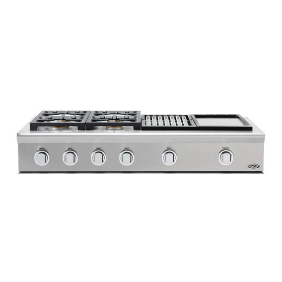
- Page 1 Professional cooktop Installation instructions CPU/CPV models La table de cuisson professionelle Guide d’installation Modèles CPU/CPV US CA...
- Page 2 WARNING! MISE EN GARDE! If the information in this manual is not Le fait de ne pas suivre toutes les instructions followed exactly, a fire or explosion may de ce manuel peut provoquer un feu ou une result causing property damage, personal explosion causant des dommages matériels, injury or death.
- Page 3 A MESSAGE TO OUR CUSTOMERS Thank you for selecting this DCS professional Cooktop. Because of this appliance’s unique features we have developed this Installation Guide. It contains valuable information on how to properly install your new appliance for years of safe and enjoyable cooking.
-
Page 4: Table Of Contents
TABLE OF CONTENTS INTRODUCTION SAFETY PRACTICES AND PRECAUTIONS MODELS PLANNING THE INSTALLATION UNPACKING AND HANDLING VENTILATION REQUIREMENTS CABINET PREPARATION BACKGUARD INSTALLATION ELECTRICAL CONNECTIONS GAS HOOK-UP TEST AND ADJUSTMENTS INSTALLER FINAL CHECKLIST WARRANTY AND SERVICE... -
Page 5: Introduction
INTRODUCTION IMPORTANT INSTALLATION INFORMATION The cooktops are tested in accordance with ANSI Z21.1 Standard for Household Cooking Gas Appliances. These cooktops must be installed in conjunction with a suitable overhead vent hood. (See ventilation requirements). Due to the professional high heat capacity of this unit, particular attention should be paid to the hood and duct work installation to ensure it meets local building codes. -
Page 6: Safety Practices And Precautions
SAFETY PRACTICES AND PRECAUTIONS When properly cared for, your new DCS Appliance has been de signed to be a safe, reliable cooking appliance. When using this restaurant caliber appliance, use it with extreme care, as this type appliance provides intense heat and can increase the accident potential. - Page 7 SAFETY PRACTICES AND PRECAUTIONS ■ Do not use aluminum foil to line any part of the cooktop. Doing so, heat will be trapped underneath it. This trapped heat can upset the cooking perfor mance and can damage the finish of the cooktop parts. ■...
- Page 8 SAFETY PRACTICES AND PRECAUTIONS ■ Clean the cooktop with caution. Avoid steam burns; do not use a wet sponge or cloth to clean the cooktop while it is hot. Some cleaners produce noxious fumes if applied to a hot surface. Follow directions provided by the cleaner manufacturer.
-
Page 9: Models
MODELS 48” CPU/CPV COOKTOP MODELS CPU/CPV-484GG CPU/CPV-486GL CPU/CPV-485GD CPU/CPV-486GD 36” CPU/CPV COOKTOP MODELS CPU/CPV-366 CPU/CPV-364GD CPU/CPV-364GL... -
Page 10: Planning The Installation
PLANNING THE INSTALLATION IMPORTANT INSTALLATION INFORMATION All cooktop models with less than a 12” clearance between combustible material and the back edge of the cooktop, require the installation of one of the two offered Wall Mount Backguards – see section ‘Backguard installation’. - Page 11 PLANNING THE INSTALLATION RECOMMENDED INSTALLATION SEQUENCE Install components in the following order: A. Vent Hood B. Backguard System (sold separately) C. Cooktop 1. Locate cooktop according to cooktop installation instructions. 2. Measure distance from counter surface to top of trim on cooktop adding 1/4” for backguard clearance. 3.
-
Page 12: Unpacking And Handling
UNPACKING AND HANDLING CAUTION: Proper equipment and adequate manpower must be used in moving the cooktop to avoid personal injury or damage to the unit. MOVING AND PLACING THE COOKTOP The cooktops have a shipping weight of approximately 228 pounds (36” models) and 324 pounds (48” models). After removal of packing materials, it is recommended that the grates and grease drip-pan (some models only) be removed to facilitate handling. -
Page 13: Ventilation Requirements
VENTILATION REQUIREMENTS A suitable exhaust hood must be installed above the cooktop. The following chart indicates the minimum blower capacity recommended for hood ventilation. STANDARD COUNTER VENTILATION ISLAND INSTALLATION INSTALLATION UNIT RECOMMENDATONS RECOMMENDATONS HOOD 23” Deep x Unit Width 30” Deep x 36” at Bottom 48”... -
Page 14: Cabinet Preparation
CABINET PREPARATION 1. To ensure professional results, the cabinet and countertop openings should be prepared by a qualified cabinet worker. We recommend having the cooktop available before cutting the opening for more precise dimension verification. 2. The clearances shown in Fig. 6 are required for all types of backguard installations. 3. - Page 15 CABINET PREPARATION 6. Cut the openings for the following installation: ■ Standard counter top installation, see Fig. 6A ■ Deep counter or island installation, see Fig. 6B NOTE: The sides or bottom of the opening may be solid combustible or non-combustible material. If the bottom is solid, provide a 6”...
- Page 16 CABINET PREPARATION 28" Countertop level 8-5/16" 5/16" 1-19/32" To Center Line of Gas Inlet 24" 2-1/2" Cabinet face for installation with projecting control panel Cabinet face for installation with flush control panel Fig. 5 26-1/2" 15/16" 12" Min. to Combustibles without Backguard Wall Mount 36”...
-
Page 17: Backguard Installation
12” clearance between combustibles and the back of Wall Mount the cooktop (above the cooking surface). See fig. 6. Low Backguard (Model #’s BGCU-1236, BGCU-1248) DCS backguards are sold separately. 12" Fig. 7 ELECTRICAL CONNECTIONS The rating label is located on the right- hand side of the cooktop, towards the front. -
Page 18: Gas Hook-Up
GAS HOOK-UP GAS REQUIREMENTS Verify the type of gas supplied to the location. The cooktop is shipped from the factory set up and adjusted for Natural Gas or LP (propane), depending on the specific model ordered. Verify that the cooktop is compatible with gas supply at the installation site before proceeding further. -
Page 19: Test And Adjustments
FIG. 11 WARNING: For warranty coverage, DCS requires that burner adjustments be made by a qualified technician at the time of installation. Extreme care should be used when adjustments are made after installation. COOKTOP BURNERS The cooktop burners are not adjustable. -
Page 20: Installer Final Checklist
INSTALLER FINAL CHECKLIST GENERAL ❑ Placement of unit. ❑ Specified clearance maintained to cabinet surfaces. ❑ Unit Level - front to back, side to side. ❑ All packaging material and tie straps removed. ❑ Backguard attached if there is less than 12” clearance from the back edge of the cooktop to combustibles behind unit. -
Page 21: Warranty And Service
WARRANTY AND SERVICE Before you call for service or assistance ... Check the things you can do yourself. Refer to the installation instructions and your user guide and check that: your product is correctly installed you are familiar with its normal operation. If after checking these points you still need assistance or parts, please refer to the Service &... - Page 22 REMARQUE : Inspecter le produit pour vérifier qu’il n’a pas été endommagé pendant l’expédition. En cas de dommages, contacter le transporteur et entamer une déclaration pour dommage. DCS by Fisher & Paykel n’est en aucun cas responsable des dommages pendant l’expédition.
- Page 23 INTRODUCTION (FR) MESURES DE SÉCURITÉ ET DE PRÉCAUTION MODÈLES PLANIFICATION DE L’INSTALLATION DÉBALLAGE ET MANIPULATION EXIGENCES EN MATIÈRE DE VENTILATION PRÉPARATION DES ARMOIRES INSTALLATION DU DOSSERET CONNEXIONS ÉLECTRIQUES BRANCHEMENT DU GAZ ESSAI ET RÉGLAGES LISTE DE CONTRÔLE FINALE DE L’INSTALLATEUR GARANTIE ET SERVICE...
-
Page 24: Introduction
INTRODUCTION INFORMATIONS IMPORTANTES CONCERNANT L’INSTALLATION (FR) Les tables de cuisson professionnelles CPU/CPV ont été testées conformément à la norme ANSI Z21.1 pour les appareils électroménagers domestiques de cuisson à gaz. Ces tables de cuisson doivent être installées avec une hotte de ventilation suspendue (voir les exigences en matière de ventilation). Étant donnée la puissance de feu professionnelle élevée de cet appareil, faites particulièrement attention à... -
Page 25: Mesures De Sécurité Et De Précaution
MESURES DE SÉCURITÉ ET DE PRÉCAUTION Votre nouvel appareil DCS fonctionnera de manière sûre et fiable pendant des années si vous en prenez bien (FR) soin. Faites extrêmement attention quand vous utilisez cet appareil de niveau professionnel, car il dégage une chaleur intense et peut augmenter les risques d’accidents. - Page 26 MESURES DE SÉCURITÉ ET DE PRÉCAUTION ■ Utilisez seulement des gants isolants secs : les gants humides sur des surfaces chaudes peuvent provoquer des (FR) brûlures causées par la vapeur. N’utilisez pas de serviette ou de linge épais à la place de gants isolants. Ne laissez pas les gants isolants toucher les brûleurs ou leurs grilles.
- Page 27 MESURES DE SÉCURITÉ ET DE PRÉCAUTION ■ Nettoyez la table de cuisson avec précaution. Évitez de vous brûler à la vapeur : n’utilisez pas d’éponge ou de (FR) linge mouillé pour nettoyer l’appareil alors qu’il est encore chaud. Certains produits de nettoyage dégagent des vapeurs nocives au contact d’une surface chaude.
-
Page 28: Modèles
MODÈLES MODÈLES DE TABLES DE CUISSON CPU/CPV 48 PO (FR) CPU/CPV-484GG CPU/CPV-486GL CPU/CPV-485GD CPU/CPV-486GD MODÈLES DE TABLES DE CUISSON CPU/CPV 36 PO CPU/CPV-366 CPU/CPV-364GD CPU/CPV-364GL... -
Page 29: Planification De L'installation
PLANIFICATION DE L’INSTALLATION INFORMATIONS IMPORTANTES CONCERNANT L’INSTALLATION (FR) Vous devez installer l’un des deux dosserets muraux disponibles si le dégagement entre les matériaux combus- tibles et le bord arrière de la table de cuisson est inférieur à 30,5 cm (12 po) - voir la section ‘Installation du dosseret’. - Page 30 PLANIFICATION DE L’INSTALLATION (FR) L’ORDRE DE L’INSTALLATION RECOMMANDÉE Installez les composants dans l’ordre suivant : A. Hotte à évacuation B. Dosseret (vendu séparément) C. Table de cuisson 1. Positionnez la table de cuisson conformément aux instructions d’installation. 2. Mesurez la distance entre la surface du comptoir et le haut de la garniture de la table de cuisson en ajoutant 6,5 mm (1/4 po) de dégagement pour le dosseret.
-
Page 31: Déballage Et Manipulation
DÉBALLAGE ET MANIPULATION MISE EN GARDE : (FR) Utilisez un équipement approprié et un nombre de personnes suffisant pour déplacer la table de cuisson afin d’éviter d’endommager l’appareil ou de blesser quelqu’un. DÉPLACEMENT ET PLACEMENT DE LA TABLE DE CUISSON Le poids à... -
Page 32: Exigences En Matière De Ventilation
EXIGENCES EN MATIÈRE DE VENTILATION Vous devez installer une hotte à évacuation appropriée au-dessus de la table de cuisson. Le tableau suivant (FR) indique la capacité minimum du ventilateur recommandée pour aérer la hotte. RECOMMANDATIONS RECOMMANDATIONS APPAREIL DE CONCERNANT CONCERNANT VENTILATION L’INSTALLATION D’UN L’INSTALLATION EN ÎLOT... -
Page 33: Préparation Des Armoires
PRÉPARATION DES ARMOIRES (FR) 1. Afin d’assurer un résultat professionnel, les ouvertures de l’armoire et du comptoir doivent être préparées par un ébéniste qualifié. Nous vous recommandons de disposer de la table de cuisson avant de découper l’ouverture afin de vous assurer de manière plus précise de l’exactitude des dimensions. 2. - Page 34 PRÉPARATION DES ARMOIRES 6. Découpez les ouvertures pour l’installation suivante : (FR) ■ Installation standard du comptoir, voir fig. 6A ■ Installation d’un comptoir profond ou d’un îlot, voir fig. 6B REMARQUE : Les côtés ou la partie inférieure de la ouverture peuvent être constitués de matériaux pleins combustibles ou non-combustibles.
- Page 35 PRÉPARATION DES ARMOIRES (FR) 71,1 cm (28 po) Niveau du comptoir 21,1 cm 7,9 cm (8-5/16 po) (5/16 po) 4 cm (1-19/32 po) de la ligne médiane à l'admission de gaz 61 cm (24 po) 6,4 cm (2-1/2po) Face d'armoire à installer avec panneau de contrôle dépassant Face d'armoire à...
-
Page 36: Installation Du Dosseret
à 30,5 cm (12 po). Voir fig. 6. 30,5cm (Modèle BGCU-1236, BGCU-1248) (12po) Les dosserets DCS sont vendus séparément. Fig. 7 CONNEXIONS ÉLECTRIQUES L’étiquette signalétique est située sur le côté droit de l’appareil, vers le devant. -
Page 37: Branchement Du Gaz
BRANCHEMENT DU GAZ EXIGENCES CONCERNANT LE GAZ (FR) Vérifiez le type de gaz alimentant le site. La table de cuisson est réglée en usine pour fonctionner au gaz naturel ou propane selon le modèle spécifique commandé. Avant d’aller plus loin, vérifiez que La table de cuissonest compatible avec l’alimentation en gaz du site où... -
Page 38: Essai Et Réglages
à nouveau l’absence de fuite. FIG. 11 AVERTISSEMENT : Aux fins de la garantie, DCS exige que le réglage des brûleurs soit effectué par un technicien qualifié au moment de l’installation. Faites extrêmement attention quand des réglages sont effectués après l’installation. - Page 39 ESSAI ET RÉGLAGES REMARQUE CONCERNANT L’ALLUMAGE DU BRÛLEUR DE LA TABLE DE CUISSON (FR) Les brûleurs à tête scellée de la table de cuisson permettent un réglage continu de la flamme et leurs boutons de réglage ne comportent pas de position fixe entre les niveaux HI et LO. Pour allumer le brûleur à tête scellée de la table de cuisson, enfoncez le bouton de réglage et tournez-le vers la gauche à...
-
Page 40: Liste De Contrôle Finale De L'installateur
LISTE DE CONTRÔLE FINALE DE L’INSTALLATEUR GÉNÉRALITÉS (FR) ❑ Emplacement de l’appareil. ❑ Dégagement spécifié respecté par rapport aux surfaces d’armoires. ❑ Appareil de niveau - de l’avant à l’arrière, d’un bord à l’autre. ❑ Matériel d’emballage et courroies d’attache enlevés, ramasse-gouttes propres et vides. ❑... -
Page 41: Garantie Et Service
GARANTIE ET SERVICE Avant d'appeler pour demander une réparation ou de l'assistance... (FR) Vérifiez les points que vous pouvez contrôler vous-même. Consultez les instructions d’installation et le guide de l’utilisateur pour vous assurer que : votre produit est installé correctement. vous êtes familier avec son fonctionnement normal. Si après la vérification de ces points, vous avez toujours besoin d’assistance ou d'une réparation, reportez-vous au document de service et de garantie pour obtenir les détails sur la garantie et les coordonnées d'un Centre de service autorisé... - Page 44 www.dcsappliances.com Copyright © Fisher & Paykel 2014. All rights reserved. The product specifications in this booklet apply to the specific products and models described at the date of issue. Under our policy of continuous product improvement, these specifications may change at any time. You should therefore check with your Dealer to ensure this booklet correctly describes the product currently available.
Need help?
Do you have a question about the CPV Series and is the answer not in the manual?
Questions and answers