
Related Manuals for Pfeiffer Vacuum TC 400 DN


Summary of Contents for Pfeiffer Vacuum TC 400 DN
- Page 1 OPERATING INSTRUCTIONS Translation of the original instructions TC 400 DN Electronic Drive Unit...
-
Page 2: Table Of Contents
Table of contents Table of contents About this manual ..........4 1.1 Validity. - Page 3 RS-485 ..........26 The Pfeiffer Vacuum parameter set ....... . 27 7.1 General .
-
Page 4: About This Manual
About this manual Validity This operating manual is for customers of Pfeiffer Vacuum. It describes the functioning of the designated product and provides the most important information for safe use of the unit. The description follows applicable EU guidelines. All information provided in this operating manual refers to the current state of the product's development. -
Page 5: Pictographs
About this manual 1.2.2 Pictographs Prohibition of an action to avoid any risk of accidents, the disregarding of which may result in serious accidents Warning of a displayed source of danger in connection with operation of the unit or equipment Command to perform an action or task associated with a source of dan- ger, the disregarding of which may result in serious accidents Important information about the product or this document... -
Page 6: Safety
● Power supply: The turbopump power supply must apply to the requirements of dou- ble insulation between mains input voltage and operating voltage according to the reg- ulations of IEC 61010 and IEC 60950. Therefore Pfeiffer Vacuum recommends to use exclusively original-power packs and -accessories. Only in this case Pfeiffer Vacuum is able to guarantee the compliance of the European and North American guidelines. -
Page 7: Proper Use
Service. Functional safety The drive unit (electronic drive unit) TC 400 DN performs the safety function "Safe Lim- ited Speed" according to EN 61800-5-2. In case of excess rotation speed the commuta- tion of the pump motor is switched off and the drive transferred into the safe condition. -
Page 8: Product Description
● www.tuvdotcom.com ● TUVdotCOM-ID 0000021320 3.1.1 Product characteristics The electronic drive unit TC 400 DN is an integrated component of the turbopump. It's purpose is to drive, monitor and control the entire pump. Characteristics TC 400 DN Connection voltage TC... -
Page 9: Function
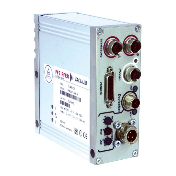
DeviceNet address selection switch LSD General connection description DC in Casing plug with bayonet locking for the voltage supply between Pfeiffer Vacuum mains packs and the electronic drive unit. Accessory M12 socket with screw coupling for the connection of Pfeiffer Vacuum accessories. -
Page 10: Connection Diagram
Relay 2 + U B (+24 / +48 V DC ± 10 %) Relay 2 Relay 2 Relay 3 Relay 3 DO Remote priority active RS485 D+ RS485 D- GND* Fig. 3: Connection diagram and assignment of the TC 400 DN... -
Page 11: Connection "Devicenet
Connection "DeviceNet" Connection "DeviceNet" Connections The turbopump can be connected to a DeviceNet bus system using the connector (5 - pin, sealed micro) labelled "DeviceNet" on the electronic drive unit. A supply voltage (V+, V-) is required to supply this connection in addition to the supply voltage for the electronic drive unit. -
Page 12: Baud Rate
Connection "DeviceNet" 5.2.2 Baud rate The DeviceNet baud rate is set manually using the "RATE" selector switches or via De- viceNet. Position Meaning RATE 125 kBit/s 250 kBit/s 500 kBit/s Baud rate via DeviceNet Setting the baud rate manually Set the selector switches to the desired value. –... -
Page 13: Cyclical Data Exchange (Poll I/O Connection)
Connection "DeviceNet" 5.3.2 Cyclical data exchange (poll I/O connection) For the cyclical data exchange, multiple DeviceNet objects are combined to form assem- blies (4.x.3.). One assembly is selected for each direction (input/output data). The follow- ing assemblies are available for selection: Input data (produced data, pump -->... -
Page 14: Led Operation
USINT Minor Revision USINT 1.1.5 Status WORD 1.1.6 Serial Number UDINT 1.1.7 Product Name SHORT_STRING get TC 400 DN 1.1.100 Status Code SHORT_STRING get 5.5.2 Message Router This object provides no attributes and services. 5.5.3 DeviceNet Path Name Data type... -
Page 15: Assembly
Connection "DeviceNet" Instance 1 Master’s MAC ID USINT 3.1.6 MAC ID Switch Changed BOOL 3.1.7 Baud Rate Switch Changed BOOL 3.1.8 MAC ID Switch Value USINT 3.1.9 Baud rate Switch Value USINT 5.5.4 Assembly Path Name Data type Service Comment 4.0.1 Revision UINT... -
Page 16: Connection
Connection "DeviceNet" Instance 101 (input): pump status, speed, current, temperatures Bearing Temperature 2 x BYTE (INT) 49.3.6 Pump Temperature 2 x BYTE (INT) 49.101.6 Instance 103 (output): pump/speed control, set speed, vent valve cfg 4.103.3 Data ARRAY of get, set Pump On BYTE 9.1.3... -
Page 17: Register
Connection "DeviceNet" Instance 2: Poll I/O connection 5.2.13 Produced Connection USINT Path Length 5.2.14 Produced Connection UINT Path 5.2.15 Consumed Connection Packed EPATH Path Length 5.2.16 Consumed Connection UINT Path 5.2.17 Production Inhibit Time Packed EPATH get, set 5.2.18 Connection Timeout USINT Multiplier 5.5.6... -
Page 18: Ac/Dc Drive
Connection "DeviceNet" Instance 2: TMS/Heating 9.2.3 Value BOOL get, set – 0: TMS/Heating off – 1: TMS/Heating released 9.2.5 Fault Action BOOL get, set – 0: TMS/Heating off – 1: Hold last state 9.2.6 Fault Action BOOL get, set 9.2.7 Idle Action BOOL get, set... -
Page 19: S-Device Supervisor
Connection "DeviceNet" Instance 1 42.1.102 IMC Current Intermediate circuit current (100 mA) e.g. 123 read => 12.3 A Max Rated 42.1.103 Max Rated Speed Con- get, set Nominal rotation speed (rpm/2 Speed Scale firmation 5.5.10 S-Device Supervisor Path Name Data type Service Comment 48.0.1... -
Page 20: S-Analog Sensor
Connection "DeviceNet" Instance 1 Manufacturer Excep- BYTE see below tion Detail 1 48.1.15 Alarm Enable BOOL get, set 48.1.16 Warning Enable BOOL get, set 48.1.23 Run Hours UDINT Pump operating hours (h) For Exception Detail Alarm and Exception Detail Warning applies: Bit Common Ex. -
Page 21: Interfaces
Connection "DeviceNet" 5.5.12 Interfaces Path Name Data Type Service Comment 101.0.1 Revision UINT 101.0.2 Max Instance UINT 101.0.3 Number of Instances UINT 101.0.16 Current Permission BYTE get, set 101.0.17 Permission Locked BOOL get, set – 0: other interfaces approved to operation –... -
Page 22: Data Types
Connection "DeviceNet" Instance 1: Backing pump 102.1.21 Switch-Off Threshold UINT get, set 0-1000 W 102.1.22 Switch-On Threshold UINT get, set 0-1000 W Instance 7: Rotation speed switch point 102.7.17 Configuration USINT get, set 0-1 (see p. 33, chap. 7.4) 102.7.18 Status BOOL –... -
Page 23: Connection "Remote
Remote control is possible via the 26-pin D-sub connector labelled "remote" on the elec- tronic drive unit. The accessible individual functions are mapped to "PLC levels". Remove the remote plug from the TC 400 DN and connect a remote control unit. Pin assignment of the connector according to table. -
Page 24: Operation Via "Remote" Connection
The digital inputs at connection "remote" are used to connect various functions of the electronic drive unit. Functions are assigned to the inputs DI1 - DI2 ex factory. These are configurable by the Pfeiffer Vacuum parameter set via Profibus or the interface RS-485. DI1 (Enable venting) / Pin 2... -
Page 25: Outputs
The digital outputs at the connection "remote" can be loaded with a maximum of 24 V / 50 mA per output. All outputs listed below are configurable by the Pfeiffer Vacuum pa- rameter set via Profibus or interface RS-485 (description related to factory settings). - Page 26 6.2.5 RS-485 One Pfeiffer Vacuum display and control panel (DCU or HPU) or an external PC can be connected respectively to the electronic drive unit via Pin 24 and Pin 25 of the connec- tion "remote" on the electronic drive unit.
-
Page 27: The Pfeiffer Vacuum Parameter Set
All function-relevant variables of a turbopump are anchored in the electronic drive unit as parameters. Each parameter has a three-digit number and a designation. Parameters can be used via Pfeiffer Vacuum display and control units or via RS-485 with the Pfeiffer Vacuum protocol. -
Page 28: Control Commands
The Pfeiffer Vacuum parameter set 7.2.3 Control commands default Display Designation Functions Unit min max 001 Heating Heating 0 = off 1 = on 002 Standby Standby 0 = off 1 = on 004 RUTimeCtrl Run-up time control 0 = off... -
Page 29: Status Requests
The Pfeiffer Vacuum parameter set default Display Designation Functions Unit min max 041 Press1HVen Enable integrated HV Sensor (IKT only) 0 = off 1 = on 2 = on, when rotation speed switchpoint attained 3 = on, when pressure switchpoint... -
Page 30: Set Value Settings
The Pfeiffer Vacuum parameter set default Display Designation Functions Unit min max DrvPower Drive power 999999 PumpCycles Pump cycles 65535 TempPwrStg Temperature power stage °C 999999 TempElec Temperature electronic °C 999999 TempPmpBot Temperature pump bottom part °C 999999 AccelDecel... -
Page 31: Accessory Connection
The Pfeiffer Vacuum parameter set 7.3.1 Accessory connection Configuration via parameters [P:035], [P:036], [P:037] or [P:038]. Option Description 0 = Fan (continous operation) Control via parameter Pumping station 1 = Venting valve, normally closed Control via parameter Enable venting, when using a venting valve which is normally closed. -
Page 32: Digital Inputs On "Remote
1,5 - 8,5 V for sensor RPT p (hPa) = 10 (U-10.5 V) 1,5 - 8,5 V for sensor IKT p (hPa) = 10 9 V: overrange 8 = Control fore-vacuum Fore-vacuum signal; control of Pfeiffer Vacuum turbo pumping stations 7.3.5 Analog input on "remote" Configuration via parameter [P:057]. -
Page 33: Operation With The Pfeiffer Vacuum Parameter Set
Ensure the gas mode is correctly set. Contact Pfeiffer Vacuum before using gases with a greater molecular mass (> 80). ● Gas mode "0" for gases with the molecular mass >39, e.g. argon. ● Gas mode "1" for gases with the molecular mass 39. -
Page 34: Set Value Power Consumption
The Pfeiffer Vacuum parameter set To avoid rotation speed fluctuations, Pfeiffer Vacuum recommends setting a some- what lower frequency in rotation speed setting mode. 7.4.4 Set value power consumption Adjust the parameter [P:708] to the desired value in %. -
Page 35: Rotation Speed Setting Mode
The Pfeiffer Vacuum parameter set When the pumping station [P:010] is switched on, the rotation speed switchpoint 1 is the signal generator. When the pumping station is switched off, signal output and status que- ry are based on the rotation speed switchpoint 2. The signal output is governed by the hysteresis between the two switchpoints. -
Page 36: Standby
Pfeiffer Vacuum recommends the intermittend mode between 5 and 10 hPa. A pressure gauge and a dosing valve are required to set the switching thresholds. -
Page 37: Standby Mode For The Backing Pump
The signal can also be used for switching a fore-vacuum safety valve. 7.4.11 Standby mode for the backing pump Connected Pfeiffer Vacuum backing pumps with speed control can be put in standby by configuring a digital output. The pump status signal switches off the backing pump when the turbo pump reaches the specified power consumption level;... -
Page 38: Vent Modes
The Pfeiffer Vacuum parameter set Sealing gas valve Switch on or off a sealing gas valve which is connected to a pre-configured output via parameter [P:050]. Sealing gas monitoring Configuration of a free and available accessory output [P:035], [P:036, [P:037], or [P:038] for option "13."... -
Page 39: Switching On/Off The Pump
The Pfeiffer Vacuum parameter set Switching on/off the pump 7.5.1 Switching on The function "pumping station" comprises turbopump operation with control of all con- nected accessories (e.g. backing pump). Switch on the supply voltage with switch S1 on the power supply. -
Page 40: Pfeiffer Vacuum Protocol For "Rs-485
Pfeiffer Vacuum Protocol for "RS-485" Pfeiffer Vacuum Protocol for "RS-485" Telegram frame The telegram frame of the Pfeiffer Vacuum protocol contains only ASCII code characters [32; 127], the exception being the end character of the message . Basically, a master ... -
Page 41: Example 2
Pfeiffer Vacuum Protocol for "RS-485" 8.2.2 Example 2 Control command Switch on pumping station (parameter [P:010], device address slave: "042") ! ASCII Control command understood Switch on pumping station (parameter [P:010], device address slave: "042") ! ASCII Applied data types... -
Page 42: Malfunctions
Error Problem Possible causes Remedy code Err001 Overspeed Call Pfeiffer Vacuum Service Only acknowledge for rotational speed f = 0 Err002 Overvoltage – Incorrect power pack used Check power pack type Check partial mains voltage Err006 Run-up fault –... - Page 43 Possible causes Remedy code Err010 Internal device error Call Pfeiffer Vacuum Service Only acknowledge for rotational speed f = 0 Err021 Drive electronics fail to identify pump Call Pfeiffer Vacuum Service Only acknowledge for rotational speed f = 0...
-
Page 44: Operation With Dcu
Malfunctions Error Problem Possible causes Remedy code Wrn116 Temperature evaluation on bearings is Call Pfeiffer Vacuum Service faulty Wrn117 High pump base temperature – Insufficient cooling Improve cooling Check deployment conditions Wrn118 High output stage temperature – Insufficient cooling ... -
Page 45: Declaration Of Conformity
EC directives: ● Electromagnetic Compatibility 2014/30/EU ● Low Voltage 2014/35/EU ● Restriction of the use of certain Hazardous Substances 2011/65/EU TC 400 DN Harmonised standards and national standards and specifications which have been ap- plied: DIN EN 61000-3-2 : 2014... - Page 46 VACUUM SOLUTIONS FROM A SINGLE SOURCE Pfeiffer Vacuum stands for innovative and custom vacuum solutions worldwide, technological perfection, competent advice and reliable service. COMPLETE RANGE OF PRODUCTS From a single component to complex systems: We are the only supplier of vacuum technology that provides a complete product portfolio.
Need help?
Do you have a question about the TC 400 DN and is the answer not in the manual?
Questions and answers