
Related Manuals for Pfeiffer Vacuum TCP 350


Summary of Contents for Pfeiffer Vacuum TCP 350
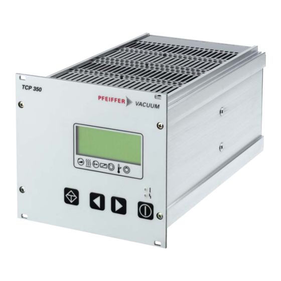
- Page 1 OPERATING INSTRUCTIONS Translation of the Original TCP 350 Electronic drive unit...
-
Page 2: Telegram Example
Dear Customer, Thank you for choosing a Pfeiffer Vacuum product. Your new electronic drive unit is designed to support you in your individual applications with maximum performance and without malfunctions. The name Pfeiffer Vacuum stands for high-quality vacuum technology, a comprehensive and complete range of top-quality products and first-class service. -
Page 3: Table Of Contents
4.9.1 Grounding unit 4.9.2 Connecting to mains power supply Interfaces Interface RS-485 Cross-linked via the RS-485 connection Pfeiffer Vacuum protocol for RS-485 interface 5.3.1 Telegram frame 5.3.2 Telegram description 5.3.3 Telegram example 1 5.3.4 Telegram example 2 5.3.5 Data types... - Page 4 Operation Switching on unit LC-display Status symbols Key functions Displaying and configuring parameters Configuring the connections with the Pfeiffer Vacuum parameter set 7.6.1 General 7.6.2 Configuring digital output and relay 7.6.3 Configuring analog output 7.6.4 Configuring accessory connection Operating modes 7.7.1 Remote control...
- Page 5 Examples of displays for the actual pressure value Tbl. 30: Behavior and meaning of the LED display Tbl. 31: Error messages of the electronic drive unit Tbl. 32: Warning messages of the electronic drive unit Tbl. 33: Accessories Tbl. 34: TCP 350 5/56...
- Page 6 Connection diagram for TCP350 with RJ45 accessory connection Fig. 7: Rotation speed control mode pin 7 and pin 26 Fig. 8: Connection of the grounding cable to the TCP 350 Fig. 9: Cross-linking of turbopumps via RS-485 interface Fig. 10: LC-display, overview Fig.
-
Page 7: About This Manual
Keep the manual for future consultation. 1.1 Validity This operating instructions is a customer document of Pfeiffer Vacuum. The operating instructions de- scribe the functions of the named product and provide the most important information for the safe use of the device. The description is written in accordance with the valid directives. The information in this op- erating instructions refers to the product's current development status. -
Page 8: Pictographs
This section describes all the stickers on the product along with their meanings. Rating plate (example) Rating plates of the devices are affixed to the housing where they Ser. Nr.: Mod.: TCP 350 can be clearly seen Mod--Nr.: PM C01 740 Input:... -
Page 9: Tbl. 2: Abbreviations Used In This Document
About this manual Abbreviation Meaning in this document Pirani transmitter [P:xxx] Electronic drive unit control parameters. Printed in bold as a three-digit number in square brackets. Frequently displayed in conjunction with a short description. Example: [P:312] software version Piezo/Pirani transmitter RP RS-485 Standard for a physical interface for asynchronous serial data transmission (Recom- mended Standard) -
Page 10: Safety
Safety 2 Safety 2.1 General safety information The following 4 risk levels and 1 information level are taken into account in this document. DANGER Immediately pending danger Indicates an immediately pending danger that will result in death or serious injury if not observed. ►... -
Page 11: Safety Precautions
Safety WARNING Risk of fatal injury due to electric shock on account of incorrect installation The device's power supply uses life-threatening voltages. Unsafe or improper installation can lead to life-threatening situations from electric shocks obtained from working with or on the unit. ►... -
Page 12: Limits Of Use Of The Product
Tbl. 3: Permissible ambient conditions 2.5 Proper use ● The electronic drive unit is used exclusively for the operation of Pfeiffer Vacuum turbopumps and their accessories. 2.6 Foreseeable improper use Improper use of the product invalidates all warranty and liability claims. Any use that is counter to the purpose of the product, whether intentional or unintentional, is regarded as misuse, in particular: ●... -
Page 13: Product Description
Tbl. 4: Product features 3.3 Function The electronic drive unit TCP 350 is used for external voltage supply, control and monitoring of turbo- pumps and connected peripheral devices. It is also possible to connect a pressure gauge. TCP 350 Ser. Nr.:78514xxx... -
Page 14: Connections
REMOTE High-density D-sub socket with 26 pins for connection and configuration of a re- mote control. RS485 RJ45 plug contact, 8-pin for connecting Pfeiffer Vacuum control units (e.g. HPU or ↑ a PC) with RS485/RS232 or RS485/USB adapter. SERVICE RJ45 plug contact, 8-pin for service purposes. -
Page 15: Installation
► Remove the mains plug from the device. ► Secure the device against unintentional restarting. The external connection of a Pfeiffer Vacuum turbopump to the electronic drive unit TCP 350 is possible with screened connection cables in different lengths from the Pfeiffer Vacuum accessories range. -
Page 16: Connection Diagram
Installation Fig. 3: Connecting turbopump to electronic drive unit 1 Electronic drive unit TCP 350 Fixing materials 2 Turbopump PE grounding cable 3 Connection "vacuum pump" Pump connection cable 4 Accessory connections Connection "PUMP" to TCP Procedure 1. Use the respective connection cable from the electronic drive unit scope of delivery or from the accessories range. - Page 17 Installation potentialfree contacts Fig. 4: Connection diagram for TCP350 with M12 accessory connection 17/56...
- Page 18 Installation Potential-free contacts Fig. 5: Connection diagram for TCP350 with M8 accessory connection 18/56...
-
Page 19: Service" Connection
Installation potential-free contacts Fig. 6: Connection diagram for TCP350 with RJ45 accessory connection 4.5 "SERVICE" connection The connection with the "SERVICE" designation on the electronic drive unit is used exclusively for serv- ice and configuration purposes. The connections are galvanically safe and are isolated from the maxi- 19/56... -
Page 20: Remote" Connection
The accessible individual functions are mapped to "PLC levels". The following specifications are the factory settings for the electronic drive unit. They can be configured with the Pfeiffer Vacuum parameter set. Required tools ● Calibrated torque wrench ●... -
Page 21: Voltage Supply
The digital inputs at the "REMOTE" connection are used to switch various electronic drive unit func- tions. Inputs DI1 to DI2 are assigned functions in the factory. You can configure them via the RS-485 interface and the Pfeiffer Vacuum parameter set. 21/56... - Page 22 Installation DI1 (release venting)/pin 2 Enable venting (venting as per venting mode) open: Venting blocked (no venting occurs) DI motor vacuum pump/pin 3 The turbopump starts up with activation of pin 4 (pumping station) and successful self-testing of the electronic drive unit. The turbopump can be switched off and switched on again during operation with the pumping station still activated.
-
Page 23: Outputs
The digital outputs at the "REMOTE" connection have a maximum load limit of 24 V/50 mA per output. All outputs listed below are configurable with the Pfeiffer Vacuum parameter set via the RS-485 inter- face (description relates to factory settings). -
Page 24: Connecting Gauges
Available types of gauges Procedure 1. As required, connect a gauge to the "GAUGE" connection. 2. The corresponding connection cable is available as a Pfeiffer Vacuum accessory. 3. If needed, set parameter [P:738] to change display name of gauge. 24/56... -
Page 25: Connecting The Electrical Supply
Connection of the grounding cable to the TCP 350 1 Ground terminal Rear of housing ● The grounding connection is mandatory for the TCP 350 in order to discharge applicative interfer- ences. ● Alternatively, the TCP 350 is grounded following installation in a rack. - Page 26 Installation 3. Insert the mains connector cable (not included in the shipment) in the "AC in" power supply plug at the rear side of the device. 4. Secure the connection with the mounting bracket. 5. Connect the mains cable to the mains power supply on the customer-side. 26/56...
-
Page 27: Interfaces
Tbl. 13: Connection assignment of the RS-485 connecting socket RJ-45 Connecting Pfeiffer Vacuum display and control units or a PC 1. Use the respective connection cable from the control unit shipment or from the accessories pro- gram. 2. Use the option to connect a PC via the USB/RS-485 converter. -
Page 28: Pfeiffer Vacuum Protocol For Rs-485 Interface
3. Make sure that all devices connected to the bus have different RS-485 device addresses [P:797]. 5.3 Pfeiffer Vacuum protocol for RS-485 interface 5.3.1 Telegram frame The telegram frame of the Pfeiffer Vacuum protocol contains only ASCII code characters [32; 127], the exception being the end character of the telegram C . Basically, a master (e.g. -
Page 29: Telegram Example
Interfaces Error message --> NO_DEF Parameter number n2–n0 no longer exists _RANGE Data dn–d0 outside the permissible range _LOGIC Logical access error 5.3.3 Telegram example 1 Data query Current rotation speed (parameter [P:309], device address slave: "123") --> ASCII Data response: 633 Hz Current rotation speed (parameter [P:309], device address Slave: "123") -->... - Page 30 Interfaces Data type Description Length Example l1 – l0 u_expo_new Positive exponential number. The 100023 is equivalent to last of both digits are the exponent 1,0 · 10 with a deduction of 20. 100000 is equivalent to 1,0 · 10 string16 Any character string with 16 char- this-is-an-example...
-
Page 31: Parameter Set
Brief description of the parameters Functions Function description of the parameters Data type Type of formatting of the parameter for the use with the Pfeiffer Vacuum protocol Access type R (read): Read access; W (write): Write access Unit Physical unit of the described variable min. -
Page 32: Status Requests
Parameter set Display Description Functions Data Unit min. max. type cess fault type Motor TMP Motor vacuum 0 = off pump 1 = on OpMode BKP Backup pump 0 = continuous opera- operating mode tion 1 = intermittent opera- tion OPMode TMP Rotation speed 0 = off, final speed oper-... -
Page 33: Tbl. 16: Status Requests
2 = air cooling Pressure Actual pressure value (Ac- 1E-12 1.0E3 tiveLine) Drv Name Drive type, electronic drive TCP 350 unit Drv Softw. Software version motor 999999 control HW Version Hardware version, elec- tronic drive unit ErrHist1 Error code history, item 1... -
Page 34: Reference Value Inputs
Parameter set 6.4 Reference value inputs Display Description Functions Data Unit min. max. default type cess type RUTimeSVal Set value run-up time SpdSwPt1 Rotation speed switch point 1 SpdSVal Set value in rotation speed setting mode Swoff BKP Backup pump switch-off 1000 threshold for intermittent operation... -
Page 35: Operation
Operation 7 Operation 7.1 Switching on unit WARNING Danger to life from electric shock in the event of a fault In the event of a fault, devices connected to the mains may be live. There is a danger to life from electric shock when making contact with live components. ►... -
Page 36: Status Symbols
Operation Line Function number Line 3 has 2 functions: ● Function 1: displays current messages, as well as messages pertaining to operation and control. ● Function 2: presentation of a required second parameter in the format [Parameter number: value]. The function for this line can be set via parameter [P:795] Service- lin in Line 1. -
Page 37: Displaying And Configuring Parameters
● Press the "ON/OFF" key ● If Line 3 = empty , "data not changed" will be displayed. 7.6 Configuring the connections with the Pfeiffer Vacuum parameter set The electronic drive unit is pre-configured with the factory default basic functions and is ready for opera- tion. -
Page 38: Configuring Digital Output And Relay
Operation Checking settings 1. Before operating with parameters, check the set value settings and control commands for their suitability for the process. 2. Remove the remote plug from the electronic drive unit. Locking and unlocking keyboard 1. Lock the keyboard via parameter [P:008] to prevent unwanted operation. –... -
Page 39: Operating Modes
Operation 7.7 Operating modes 7.7.1 Remote control Possibilities ● Operation via the TCP 350 keyboard without explicit prioritization of the operating interfaces (standard) ● Remote control via the RS-485 interface ● Control via the switching functions of the "REMOTE" connection ─ Possible to connect several TCPs Setting standard operation ►... -
Page 40: Run-Up Time
Operation P max [P:708] C-D = Gas mode "0" A-B = Gas mode "1" Fig. 11: Schematic diagram of power characteristics, example of heavy gases [P:027] = 0 Power consumption Nominal rotation speed Rotation speed Power characteristic in gas mode "0" (gases with molecular mass >... -
Page 41: Rotation Speed Setting Mode
Operation [P:017] = 0 f (%) [P:701] [P:010] [P:302] Process Fig. 12: Rotation speed switch point active Setting rotation speed switchpoint Signal output and status parameters are based on the set value for rotation speed switchpoint [P:701]. ► Set the parameter [P:701] to the required value as %. 7.7.5 Rotation speed setting mode Rotation speed setting mode reduces the speed and hence the throughput of the turbopump. -
Page 42: Stand-By
Fluctuations in the power consumption of idling turbopumps and varying fore-vac- uum pressures of the backing pumps require individual settings of the interval operation. Pfeiffer Vacuum recommends interval operation between 5 and 10 hPa. A pressure gauge and a dosing valve are required to set the switching thresholds. -
Page 43: Operation With Accessories
Operation 7.7.9 Operation with accessories Installation and operation of accessories Pfeiffer Vacuum offers a series of special, compatible accessories for its products. ● Information and ordering options for approved accessories you can find online. ● The following accessories are not included in the scope of delivery. -
Page 44: 11Transmitter Operation
Pressure measurement The electronic drive unit offers an approximate accuracy of measurement. For the precise pressure measurement, and in particular for linear transmitters in the lower pressure range, Pfeiffer Vacuum measuring instruments are ideal. Displaying active transmitters The unit detects gauge from the same image impedance group. -
Page 45: 2Temperature Monitoring
Operation Symbol LED status Display Meaning without current On, flashing "Pumping station OFF", rotation speed ≤ 60 Green On, inverse flashing "Pumping station ON", set rotation speed not reached On, constant "Pumping station ON", set rotation speed reached On, flashing "Pumping station OFF", rotation speed >... -
Page 46: Maintenance
Maintenance 8 Maintenance WARNING Danger to life from electric shock during maintenance and service work The device is only completely de-energized when the mains plug has been disconnected and the vacuum pump is at a standstill. There is a danger to life from electric shock when making contact with live components. -
Page 47: Recycling And Disposal
9.1 General disposal information Pfeiffer Vacuum products contain materials that you must recycle. ► Dispose of our products according to the following: – Iron –... -
Page 48: Malfunctions
1. Read out error codes via Pfeiffer display and control units or a PC. 2. Remove the cause of the malfunction. 3. Reset the malfunction message with parameter [P:009]. – Use preconfigured quick keys with the symbol or display tiles on Pfeiffer Vacuum display and control units. Error Problem... - Page 49 Malfunctions Error Problem Possible causes Remedy code Err040 Defective storage ● Contact Pfeiffer Vacuum Service expansion Err043 Storage of parame- ● Internal configuration error ● Contact Pfeiffer Vacuum Service ter values defective Err044 Excess temperature, ● Insufficient cooling ● Improve the cooling electronics ●...
-
Page 50: Service Solutions By Pfeiffer Vacuum
We are always focused on perfecting our core competence – servicing of vacuum components. Once you have purchased a product from Pfeiffer Vacuum, our service is far from over. This is often exactly where service begins. Obviously, in proven Pfeiffer Vacuum quality. - Page 51 Service solutions by Pfeiffer Vacuum 5. Prepare the product for transport in accordance with the provisions in the contamination declaration. a) Neutralize the product with nitrogen or dry air. b) Seal all openings with blind flanges, so that they are airtight.
-
Page 52: Accessories
Mains cable 208 V AC, NEMA 6-15 to C13, 3 m P 4564 309 ZF Connection cable from TCP 350 to HiPace with 2 accessory ports M8, 3 m PM 061 353 -T Connection cable from TCP 350 to HiPace with 2 accessory ports M12, 3 m... -
Page 53: Technical Data And Dimensions
Technical data and dimensions 13 Technical data and dimensions 13.1 Technical data Selection field TCP 350, drive electronics Part number PM C01 740 Input voltage(s) 115 / 230 V AC (-20/+15 %), 50/60 Hz Input voltage 50 Hz 115 / 230 V... -
Page 54: Declaration Of Conformity
Declaration of conformity Declaration for product(s) of the type: Display Control Unit TCP 350 We hereby declare that the listed product satisfies all relevant provisions of the following European Directives. Electromagnetic compatibility 2014/30/EU Low voltage 2014/35/EC Restriction of the use of certain hazardous substances 2011/65/EU... - Page 55 55/56...
Need help?
Do you have a question about the TCP 350 and is the answer not in the manual?
Questions and answers