
Related Manuals for Pfeiffer Vacuum TC1200


Summary of Contents for Pfeiffer Vacuum TC1200
- Page 1 OPERATING INSTRUCTIONS Translation of the Original TC 1200 Electronic drive unit...
-
Page 2: Telegram Example
Dear Customer, Thank you for choosing a Pfeiffer Vacuum product. Your new turbopump is designed to support you by its performance, its perfect operation and without interfering your individual application. The name Pfeiffer Vacuum stands for high-quality vacuum technology, a comprehensive and complete range of top-quality products and first-class service. -
Page 3: Table Of Contents
Control commands Status requests Set value settings Additional parameter for the DCU Operation Configuring the connections with the Pfeiffer Vacuum parameter set 7.1.1 Configuring the "remote" connection 7.1.2 Configuring the accessory connections 7.1.3 Select interfaces Operating modes 7.2.1 Gas type-dependent operation 7.2.2 Set value power consumption... - Page 4 Switching on the turbopump Switching off the turbopump Operation monitoring 7.6.1 Operating mode display via LED 7.6.2 Temperature monitoring Malfunctions General Error codes Warning and error messages when operating with DCU Service solutions from Pfeiffer Vacuum Declaration of conformity 4/52...
- Page 5 List of tables List of tables Tbl. 1: Stickers on the product Tbl. 2: Abbreviations used in this document Tbl. 3: Permissible ambient conditions Tbl. 4: Features of the device variant Tbl. 5: Drive power depending on the supplied mains voltage Tbl.
- Page 6 List of figures List of figures Fig. 1: TC 1200 connection panel Fig. 2: Diagram and assignments of the connection panel Fig. 3: Connecting RS-485 devices Fig. 4: Networking of several electronic drive units in RS-485 Bus Fig. 5: Schematic diagram of power characteristics, example of heavy gases [P:027] = 0 Fig.
-
Page 7: About This Manual
Keep the manual for future consultation. 1.1 Validity These operating instructions are for customers of Pfeiffer Vacuum. They describe the function of the designated product and provide the most important information for safe usage of the product. The de- scriptions comply with applicable directives. All information provided in these operating instructions refer to the current development status of the product. -
Page 8: Stickers On The Product
AI / AO Analog Input / Analog Output Ampere interrupting capacity Display Control Unit (Pfeiffer Vacuum display and control unit) DI / DO Digital Input / Digital Output Rotation speed value of a vacuum pump (frequency, in rpm or Hz) Handheld Programming Unit. -
Page 9: Safety
Safety 2 Safety 2.1 General safety instructions This document includes the following 4 risk levels and 1 information level. DANGER Imminent danger Indicates a hazardous situation which, if not avoided, will result in death or serious injury. ► Instructions on avoiding the hazardous situation WARNING Possibly imminent danger Indicates a hazardous situation which, if not avoided, could result in death or serious injury. -
Page 10: Safety Precautions
Safety DANGER Danger to life from electric shock Power supply packs that are not specified or are not approved will lead to severe injury to death. ► Make sure that the power supply pack meets the requirements for double isolation between mains input voltage and output voltage, in accordance with IEC 61010 and IEC 60950. -
Page 11: Limits Of Use Of The Product
● If the maximum permissible operating temperature of the turbopump is exceeded, the electronic drive unit first reduces the drive output and then switches it off where neces- sary. 2.5 Proper use ● The electronic drive unit is used exclusively for the operation of Pfeiffer Vacuum turbopumps and their accessories. 11/52... -
Page 12: Foreseeable Misuse
Safety 2.6 Foreseeable misuse Improper use of the product invalidates all warranty and liability claims. Any use that is counter to the purpose of the product, whether intentional or unintentional, is regarded as misuse, in particular: ● Connection to the current supply that do not comply with the provisions of IEC 61010 or IEC 60950 ●... -
Page 13: Product Description
3 Product description 3.1 Identifying the product ► To ensure clear identification of the product when communicating with Pfeiffer Vacuum, always keep all of the information on the rating plate to hand. ► Learn about certifications through test seals on the product or at www.certipedia.com... -
Page 14: Connections
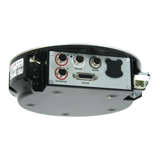
High-density sub-D bushing with 26 pins for connection and configuration of a re- mote control. RS-485 M12 socket with screw lock for the connection of Pfeiffer Vacuum control panels or PC. The use of a Y-distributor permits the integration into a bus system. Tbl. 6: Connection description of the electronic drive unit The "accessory"... -
Page 15: Installation
Installation 4 Installation 4.1 Connection diagram DANGER Danger to life from electric shock Power supply packs that are not specified or are not approved will lead to severe injury to death. ► Make sure that the power supply pack meets the requirements for double isolation between mains input voltage and output voltage, in accordance with IEC 61010 and IEC 60950. - Page 16 Installation n.c. n.c. Accessory A2 Accessory B2 24 V DC** 24 V DC** Accessory A1 Accessory B1 + 24 V DC* out DI Motor Pump CAN-H DI Pump stand 24 V DC*** DI Standby GND*** CAN-L AI+ 0-10 V DC RS 485 D + AI- GND 24 V DC* out...
-
Page 17: Remote" Connection
= 50 V DC; I = 1 A) DO remote priori- GND: off; V+: Remote priority active RS-485 D+ in accordance with the specification and Pfeiffer Vacuum proto- RS-485 D- Ground (GND) Reference earth for all digital inputs and outputs Tbl. 7: Terminal lay-out of 26-pin "remote"... -
Page 18: Connection "Rs-485
The interface with the designation "RS-485" on the electronic drive unit is intended for the connection of a Pfeiffer Vacuum display and control panel (DCU or HPU) or an external computer. The connections are galvanically safe and are isolated from the maximum supply voltage for the electronic drive unit. The electrical connections are optically decoupled internally. -
Page 19: Tbl. 9: Terminal Lay-Out Of The Power Supply Connector
Terminal lay-out of the power supply connector Establishing mains connection 1. Order a corresponding power supply cable from the Pfeiffer Vacuum accessories range. 2. Assemble your own power supply cable using the HAN 3A connecting socket from the shipment. 3. Plug mains cable into the mains connection "AC in". -
Page 20: Interfaces
The interface with the designation "RS-485" on the electronic drive unit is intended for the connection of a Pfeiffer Vacuum display and control panel (DCU or HPU) or an external computer. The connections are galvanically safe and are isolated from the maximum supply voltage for the electronic drive unit. The electrical connections are optically decoupled internally. -
Page 21: Pfeiffer Vacuum Protocol For Rs-485 Interface
3. Connect all devices to the bus with RS-485 D+ and RS-485 D-. 5.2 Pfeiffer Vacuum protocol for RS-485 interface 5.2.1 Telegram frame The telegram frame of the Pfeiffer Vacuum protocol contains only ASCII code characters [32; 127], the exception being the end character of the telegram C. . Basically, a master (e.g. -
Page 22: Telegram Example
Interfaces Control command --> Data response / Control command understood --> Error message --> NO_DEF Parameter number n2–n0 no longer exists _RANGE Data dn–d0 outside the permissible range _LOGIC Logical access error 5.2.3 Telegram example 1 Data query Current rotation speed (parameter [P:309], device address slave: "123") -->... - Page 23 Interfaces Data type Description Length Example l1 – l0 u_expo Positive exponential number 1.2E-2 corresponds with 1,2 · 10 005E8 corresponds with 5 · 10 string Any character string with 6 charac- TC_110, TM_700 ters. ASCII codes between 32 and boolean_new Logical value (false/true) 0 corresponds with false...
-
Page 24: Parameter Set
Important settings and function-related characteristics are factory-programmed into the electronic drive unit as parameters. Each parameter has a three-digit number and a description. The use of the parame- ter is possible via Pfeiffer Vacuum displays and control panels, or externally via RS-485 using Pfeiffer Vacuum protocol. - Page 25 Parameter set Display Designa- Functions Data Unit min. max. tions type cess fault type Cfg DO2 Configuration 0 = Rotation speed switch output DO2 point reached 1 = No error 2 = Error 3 = Warning 4 = Error and/or warning 5 = Set rotation speed reached 6 = Pump on 7 = Pump accelerating...
- Page 26 Parameter set Display Designa- Functions Data Unit min. max. tions type cess fault type Cfg Acc A1 Configuration 0 = fan accessory 1 = Venting valve, closed with- connection out current 2 = Heater 3 = Backing pump 4 = Fan (temperature control- led) 5 = Sealing gas 6 = Always "0"...
-
Page 27: Status Requests
Parameter set Display Designa- Functions Data Unit min. max. tions type cess fault type CtrlViaInt Operation of 1 = remote the interface 2 = RS-485 4 = PV.can 8 = Fieldbus 16 = E74 255 = Unlock interface selec- tion IntSelLckd Interface se- 0 = off... -
Page 28: Set Value Settings
Parameter set Display Designations Func- Data Access Unit min. max. tions type type fault OpHrsElec Drive electronics operating 65535 hours Nominal Spd Nominal rotation speed 999999 (Hz) DrvPower Drive power 999999 PumpCycles Pump cycles 65535 TempPwrStg Final stage temperature °C 999999 TempElec Electronics temperature... -
Page 29: Additional Parameter For The Dcu
The basic parameter set is set in the electronic drive unit ex-factory. For controlling con- nected external components (e.g. vacuum measuring instruments), additional parameters (extended parameter set) are available in the corresponding Pfeiffer Vacuum display and control panels. ● Refer to the corresponding operating instructions of the respective components. - Page 30 Parameter set Display Description Functions Data Access Unit min. max. type type fault Param set Parameter set 0 = Basic pa- rameter set 1 = Extended parameter set Servicelin Insert service line Tbl. 16: Parameter for DCU functions 30/52...
-
Page 31: Operation
Operation 7 Operation 7.1 Configuring the connections with the Pfeiffer Vacuum parameter set The electronic drive unit is pre-configured with the factory default basic functions and is ready for opera- tion. For individual requirements, you can configure most connections for the electronic drive unit with the parameter set. -
Page 32: Configuring The Accessory Connections
(U-5.5 V) (U-10.5 V) 1.5 - 8.5 V for sensor IKT p (hPa) = 10 9 V: Exceed 8 = Fore-vacuum control Fore-vacuum side; Control of Pfeiffer Vacuum turbo pumping stations Tbl. 19: Analog output Option Description 0 = Switched off... -
Page 33: Select Interfaces
► Make sure that the gas mode is set correctly by [P:027] in the electronic drive unit. ► Consult Pfeiffer Vacuum before you use gases with higher molecular masses (> 80). High gas throughput and high rotation speed lead to strong friction heating of the rotor. To avoid over- heating, power to rotation speed characteristics are implemented in the electronic drive unit. -
Page 34: Set Value Power Consumption
Operation P max [P:708] Fig. 5: Schematic diagram of power characteristics, example of heavy gases [P:027] = 0 Power consumption Power characteristic in gas mode "0" (gases with molecu- lar mass > 39, e.g. Argon) Rotation speed Power characteristic in gas mode "1" (gases with molecu- lar mass ≤... - Page 35 Operation Rotation speed switch point 1 [P:017] = 0 f (%) [P:701] [P:010] [P:302] Process Fig. 6: Rotation speed switch point 1 active Adjusting rotation speed switch point 1 Signal output and status parameters are based on the set value for the rotation speed switch point 1 [P:701].
-
Page 36: Rotation Speed Setting Mode
3. Check the set rotation speed (parameter [P:308] or [P:397]). 7.2.6 Standby Pfeiffer Vacuum recommends standby mode for the turbopump during process and production stops. When standby mode is active, the electronic drive unit reduces the rotation speed of the turbo pump. -
Page 37: Backing Pump Operating Modes
Fluctuations in the power consumption of idling turbopumps and varying fore-vac- uum pressures of the backing pumps require individual settings of the interval operation. Pfeiffer Vacuum recommends interval operation between 5 and 10 hPa. A pressure gauge and a dosing valve are required to set the switching thresholds. -
Page 38: Backing Pump Standby Mode
2. Use this signal for the control of a fore-vacuum safety valve. 7.2.9 Backing pump standby mode In case you are using a Pfeiffer Vacuum backing pump with rotation speed control, this can be used in standby mode by configuring the digital output [P:019] or [P:024]. The power consumption of the turbo- pump has a direct influence on the rotation speed of the backing pump. -
Page 39: 11Venting Modes
The digital inputs at the "remote" connection are used to switch various electronic drive unit functions. As a factory default, inputs DI1 – DI2 have functions that you can configure with the Pfeiffer Vacuum parameter set via the RS-485 interface. -
Page 40: Tbl. 26: Di Motor Pump/Pin
Operation DI motor pump/pin 3 With pin 4 activated (pumping station) and successfully completed self-test of the electronic drive unit, the turbopump is initiated. During operation the turbopump can be switched off and back on again, with the pumping station still active, without venting the turbopump. Status Description Turbo pump motor on... -
Page 41: Outputs
7.3.3 Outputs The digital outputs at the "remote" connection have a maximum load limit of 24 V/50 mA per output. All outputs listed below are configurable with the Pfeiffer Vacuum parameter set via the RS485 interface (description relates to factory settings). -
Page 42: Rs-485
► Connect only suitable devices to the bus system. A Pfeiffer Vacuum display and control unit (DCU or HPU) or an external PC can be connected via pins 24 and 25 of the electronic drive unit's "remote" connection. A USB interface (PC) can be connected via the USB/RS-485-converter. -
Page 43: Operation Monitoring
7.6.1 Operating mode display via LED LEDs on the electronic drive unit show the basic operating states of the vacuum pump. A differentiated error and warning display is only possible for operation with the Pfeiffer Vacuum display and control unit or a PC. -
Page 44: Malfunctions
● Only acknowledge for rotational speed f = 0 faulty Err010 Internal device error ● Device defective ● Contact Pfeiffer Vacuum Service. ● Only acknowledge for rotational speed f = 0 Err021 Electronic drive unit ● Incompatible software ver- ● Contact Pfeiffer Vacuum Service. - Page 45 Malfunctions Error Problem Possible causes Remedy code Err043 Internal configuration er- ● Device defective ● Contact Pfeiffer Vacuum Service. Err044 Excess temperature, ● Insufficient cooling ● Improve the cooling electronics ● Check the operating conditions Err045 Excess temperature, ● Insufficient cooling ●...
- Page 46 Problem Possible causes Remedy code Err810 Internal configuration er- ● Incompatible software ver- ● Contact Pfeiffer Vacuum Service. sion ● Only acknowledge for rotational speed f = 0 Err815 Magnetic bearing over- ● Impacts, vibrations ● Contact Pfeiffer Vacuum Service.
-
Page 47: Warning And Error Messages When Operating With Dcu
Malfunctions Error Problem Possible causes Remedy code Wrn115 Pump lower part tem- ● Device defective ● Contact Pfeiffer Vacuum Service. perature evaluation faulty Wrn116 Bearing temperature ● Device defective ● Contact Pfeiffer Vacuum Service. evaluation faulty Wrn117 Pump lower part high ●... -
Page 48: Service Solutions From Pfeiffer Vacuum
We are consistently striving to perfect our core competence, service for vacuum components. And our service is far from over once you’ve purchased a product from Pfeiffer Vacuum. It often enough really just begins then. In proven Pfeiffer Vacuum quality, of course. - Page 49 Service solutions from Pfeiffer Vacuum 5. Prepare the product for transport in accordance with the details in the declaration of contamination. a) Neutralize the product with nitrogen or dry air. b) Close all openings with airtight blank flanges. c) Seal the product in appropriate protective film.
-
Page 50: Declaration Of Conformity
DIN EN 61000-3-3: 2013 DIN EN 61010-1: 2011 DIN EN 61326-1: 2013 DIN EN 62061: 2013 DIN EN IEC 63000: 2019 Semi F47-0200 Semi S2-0706 Signature: Pfeiffer Vacuum GmbH Berliner Straße 43 35614 Asslar Germany (Daniel Sälzer) Asslar, 2019-07-18 Managing Director... - Page 51 51/52...
Need help?
Do you have a question about the TC1200 and is the answer not in the manual?
Questions and answers