Table of Contents
Advertisement
Quick Links
Advertisement
Table of Contents

Related Manuals for Pfeiffer Vacuum TC 1200 EC


Summary of Contents for Pfeiffer Vacuum TC 1200 EC
- Page 1 TC 1200 EC Electronic Drive Unit Operating Instructions...
-
Page 2: Table Of Contents
6.3 Cross-linking via the connection RS-485 ......20 The Pfeiffer Vacuum parameter set ....... . 21 7.1 General . -
Page 3: About This Manual
About this manual Validity This operating manual is for customers of Pfeiffer Vacuum. It describes the functioning of the designated product and provides the most important information for safe use of the unit. The description follows applicable EU guidelines. All information provided in this operating manual refers to the current state of the product's development. - Page 4 About this manual Pictographs Prohibition of an action or activity in connection with a source of danger, the disregarding of which may result in serious accidents Warning of a displayed source of danger in connection with operation of the unit or equipment Command to perform an action or task associated with a source of dan- ger, the disregarding of which may result in serious accidents Important information about the product or this document...
-
Page 5: Safety
Do not independently modify or change the pump and electrical equipment. Make sure that the system is integrated in an emergency off safety circuit. Consult Pfeiffer Vacuum for special requirements. WARNING Danger due to lack of power disconnection device Pump and electronic drive unit are not equipped with a power disconnection device. -
Page 6: Proper Use
Following installation into a plant and before commissioning, the operator must check the entire system for compliance with the valid EU directives and reassess it accord- ingly. ● The electronic drive unit TC 1200 EC operates designated Pfeiffer Vacuum turbo- pumps and their accessories. Improper use Improper use will cause all claims for liability and warranties to be forfeited. -
Page 7: Product Description
For information about other certifications, if applicable, please see the signet on the prod- uct or: ● www.tuvdotcom.com ● TUVdotCOM-ID 0000021320 The electronic drive unit TC 1200 EC is an integrated component of the turbopump. It's Product characteris- purpose is to drive, monitor and control the entire pump. tics... -
Page 8: Function
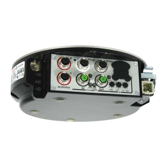
M12 socket (D coded) with threaded coupling and L/A-LED for connecting an Ether- CAT cable to the next device. RS-485 M12 socket with screw coupling for the connection of a Pfeiffer Vacuum control unit or a PC. The use of a Y-connector enables the series connection in a bus system. Accessory M12 socket with screw coupling for the connection of Pfeiffer Vacuum accessories. -
Page 9: Connecting To The Mains Power Supply
Do not independently modify or change the pump and electrical equipment. Make sure that the system is integrated in an emergency off safety circuit. Consult Pfeiffer Vacuum for special requirements. WARNING Danger due to lack of power disconnection device Pump and electronic drive unit are not equipped with a power disconnection device. -
Page 10: Connection Diagram
24 V DC** Accessory A1 Accessory B1 CAN-H 24 V DC*** GND*** CAN-L n.c. RS 485 D + 24 V DC* out GND* RS 485 D - n.c. n.c. Fig. 4: Connection diagram and assignment of the TC 1200 EC... -
Page 11: Connection "Ethercat
Insert the incoming cable from the control unit into EtherCATIN. Connect the bus connection to other devices to EtherCATOUT. The use of Ethernet switches and hubs is not supported. Use the "TC 1200 EC.xml" ESI file for configuration (included in the scope of supply). Configuration Device identification EtherCAT devices are addressed using their position in the bus. -
Page 12: Led Operation
"BOOTSTRAP" Booting error Process data Process output data ● Process output data are defined as follows: Default RxPDO (control -> TC 1200 EC, "output"), CoE 1600h.1-4 (1 byte) Byte.Bit Meaning 7000.01 Turbo Start Stop Pumping station (0: off, 1: on) 7000.02 Turbo Reset Alarm... -
Page 13: Service Data
Connection "EtherCAT" Byte.Bit Meaning 6000.02 Normal Normal operation (0: no, 1: yes) 6000.03 Acceleration Pump is accelerating (0: no, 1: yes) 6000.04 Deceleration Pump is decelerating (0: no, 1: yes) 6000.05 Remote / Local Control via EtherCAT (0: yes, 1: no) 6000.07 Turbo Low Speed Standby (0: off, 1: on) 6000h.09h Alarm... - Page 14 FW Update Funct. Gen. Number (1) UDINT 1. Idx = Index, sIdx = Sub-index, hexadecimal 2. RO = Read only, RW = Read/write, P = Suitable for process data Input data (TC 1200 EC -> control) sIdx Name Type Access...
- Page 15 Connection "EtherCAT" sIdx Name Type Access Description Speed Status USINT RO P 0: Stopped (< 60 min 1: Accelerating 2: At speed 3: Decelerating Actual Speed (rel.) SINT RO P Actual Speed (abs.) DINT RO P Ready for Process BOOL RO P Rotation speed switchpoint at- tained...
- Page 16 Total Time Powered UDINT RO P 1. Idx = Index, sIdx = Sub-index, hexadecimal 2. RO = Read only, RW = Read/write, P = Suitable for process data Output data (control -> TC 1200 EC) sIdx Name Type Access Description...
- Page 17 : 01 00 00 00 status USINT response BYTE() 1. Idx = Index, sIdx = Sub-index, hexadecimal 2. RO = Read only, RW = Read/write, P = Suitable for process data Configuration data (control -> TC 1200 EC) sIdx Name Type Access Description 4001 Cfg Pump Operation Intf.
- Page 18 Connection "EtherCAT" sIdx Name Type Access Description ACC A2 Configuration USINT See 4005.81 ACC B2 Configuration USINT See 4005.81 4009 Cfg Interface Operation DI1 Configuration USINT 0: Deactivated 1: Enable venting 2: Heating 3: Sealing gas 4: Run-up time monitoring 5: Rotation speed setting mode DI2 Configuration USINT...
-
Page 19: Connection "Rs-485
Connection "RS-485" Connections A Pfeiffer Vacuum display and control panel (DCU or HPU) or an external PC can be connected to the electronic drive unit via the connection designated "RS-485". The inter- face is electrically isolated from the maximum supply voltage of the electronic drive unit. -
Page 20: Cross-Linking Via The Connection Rs-485
Connection "RS-485" Cross-linking via the connection RS-485 USB/RS485-converter USB/RS485-converter RS 485 CAUTION Danger of electric shock The insulation measures of the bus system are designed only for use with safety extra- low voltage. Connect only suitable devices to the bus system. ... -
Page 21: The Pfeiffer Vacuum Parameter Set
All function-relevant variables of a turbopump are anchored in the electronic drive unit as parameters. Each parameter has a three-digit number and a designation. Parameters can be used via Pfeiffer Vacuum display and control units or via RS-485 with the Pfeiffer Vacuum protocol. - Page 22 The Pfeiffer Vacuum parameter set Control commands default Display Designation Functions Unit min max 001 Heating Heating 0 = off 1 = on 002 Standby Standby 0 = off 1 = on 004 RUTimeCtrl Run-up time control 0 = off...
- Page 23 The Pfeiffer Vacuum parameter set default Display Designation Functions Unit min max 045 Cfg Rel R1 Configuration Relay 1 Options see [P:019] 046 Cfg Rel R2 Configuration Relay 2 Options see [P:019] 047 Cfg Rel R3 Configuration Relay 3...
-
Page 24: Configuring The Connections
The Pfeiffer Vacuum parameter set default Display Designation Functions Unit min max TMSactTemp active temperature of TMS heating °C 999999 TMS steady TMS temperature engaged AccelDecel Acceleration / Deceleration rpm/s 999999 TempBearng Temperature bearing °C 999999 TempMotor Temperature motor °C... - Page 25 The Pfeiffer Vacuum parameter set Option Description 3 = Backing pump Control via parameters Pumping station and operation mode backing pump 4 = Fan (temperature controlled) Control via parameter Pumping station and temperature thresholds 5 = Sealing gas Control via parameters Pumping station and Sealing gas...
-
Page 26: Operation With The Pfeiffer Vacuum Parameter Set
Interface selection via [P:060] 1 = on Interface selection locked Operation with the Pfeiffer Vacuum parameter set The electronic drive unit is pre-programmed in the factory. This guarantees proper, reli- Factory settings able turbopump operation without the need for additional configuration. - Page 27 Ensure the gas mode is correctly set. Contact Pfeiffer Vacuum before using gases with a greater molecular mass (> 80). ● Gas mode "0" for gases with the molecular mass >39, e.g. argon. ● Gas mode "1" for gases with the molecular mass ≤ 39.
- Page 28 The Pfeiffer Vacuum parameter set The rotation speed switchpoint can be used for the message "Pump operational for the Adjusting the rotation process". Overrunning or underrunning the active rotation speed switchpoint activates or speed switchpoint deactivates a signal at the pre-configured output on the electronic drive unit and at the status parameter [P:302].
- Page 29 Maintain the permissible rotation speed range of the turbopump (please refer to the technical data in the operating instructions for the respective turbopump). Pfeiffer Vacuum recommends standby mode for the turbopump during process and pro- Standby duction stops. When standby mode is active, the electronic drive unit reduces the rotation speed of the turbopump.
- Page 30 Pfeiffer Vacuum recommends the intermittend mode between 5 and 10 hPa. A pressure gauge and a dosing valve are required to set the switching thresholds.
- Page 31 The Pfeiffer Vacuum parameter set Depending on the configuration, various accessories can be connected to the turbopump Operation with acces- and controlled via parameter of the electronic drive unit. sories Heating Switch on or off the heating via parameter [P:001].
-
Page 32: Switching On/Off The Pump
The Pfeiffer Vacuum parameter set Switching on/off the pump The function "pumping station" comprises turbopump operation with control of all con- Switching on nected accessories (e.g. backing pump). Parameter [P:023] = 1 Parameter [P:010] = 1 Ongoing (and removed) error messages are reset. After a successfully completed self- test, the electronic drive unit sets the turbopump motor and all connected accessories into operation depending on their configuration. -
Page 33: Pfeiffer Vacuum Protocol For "Rs-485
Pfeiffer Vacuum Protocol for "RS-485" Pfeiffer Vacuum Protocol for "RS-485" Telegram frame The telegram frame of the Pfeiffer Vacuum protocol contains only ASCII code characters [32; 127], the exception being the end character of the message . Basically, a master ... -
Page 34: Applied Data Types
Pfeiffer Vacuum Protocol for "RS-485" Example 2 Control command Switch on pumping station (parameter [P:010], device address slave: "042") ! ASCII Control command understood Switch on pumping station (parameter [P:010], device address slave: "042") ! ASCII Applied data types Data type... -
Page 35: Malfunctions
Problem Possible cause Remedy code Err001 Excess rotation speed Contact Pfeiffer Vacuum Service Reset at rotation speed f = 0 only Err002 Overvoltage – Wrong mains input voltage Check the mains input voltage Reset at rotation speed f = 0 only ... - Page 36 Possible cause Remedy code Err010 Internal device fault Contact Pfeiffer Vacuum Service Reset at rotation speed f = 0 only Err021 Electronic drive unit does not recognize Contact Pfeiffer Vacuum Service Reset at rotation speed f = 0 only...
- Page 37 Malfunctions Error Problem Possible cause Remedy code Wrn143 High temperature operating fluid pump – Cooling deficient Optimize cooling Check the ambient conditions Wrn168 High deceleration – Rate of pressure rise too high; Venting Check and optimize the venting rate rate to high (pump specific)
-
Page 38: Declaration Of Conformity
We hereby declare that the product cited below satisfies all relevant provisions accord- ing to the following EC directives: ● Electromagnetic Compatibility 2004/108/EC ● Low Voltage 2006/95/EEC TC 1200 EC Harmonised standards and national standards and specifications which have been ap- plied: DIN EN 61000-3-2 : 2008... - Page 39 Vacuum solutions Pfeiffer Vacuum stands for innovative and custom from a single source vacuum solutions worldwide, technological perfection, competent advice and reliable service. Complete range From a single component to complex systems: of products We are the only supplier of vacuum technology that provides a complete product portfolio.
Need help?
Do you have a question about the TC 1200 EC and is the answer not in the manual?
Questions and answers