
Subscribe to Our Youtube Channel
Related Manuals for Pfeiffer Vacuum TC 110 RS


Summary of Contents for Pfeiffer Vacuum TC 110 RS
- Page 1 OPERATING INSTRUCTIONS Translation of the Original TC 110 RS Electronic drive unit...
-
Page 2: Telegram Example
Dear Customer, Thank you for choosing a Pfeiffer Vacuum product. Your new electronic drive unit is designed to support you in your individual applications with maximum performance and without malfunctions. The name Pfeiffer Vacuum stands for high-quality vacuum technology, a comprehensive and complete range of top-quality products and first-class service. -
Page 3: Table Of Contents
Parameter set General Control commands Status requests Set value settings Additional parameters for the control unit Operation Configuring the connections with the Pfeiffer Vacuum parameter set 7.1.1 Configure digital inputs 7.1.2 Configure the digital outputs 7.1.3 Configure analog output 3/50... - Page 4 7.5.2 Temperature monitoring Recycling and disposal General disposal information Dispose of electronic drive unit Malfunctions General Error codes Warning and malfunction messages when operating with control units Service solutions by Pfeiffer Vacuum EC Declaration of Conformity UK Declaration of Conformity 4/50...
- Page 5 List of tables List of tables Tbl. 1: Stickers on the product Tbl. 2: Abbreviations used in this document Tbl. 3: Permissible ambient conditions Tbl. 4: Data for use in safety-related applications in accordance with IEC 61508 and IEC 62061 Tbl.
- Page 6 List of figures List of figures Fig. 1: Connection panel TC 110 RS Fig. 2: Connection diagram for TC 110 RS with connection cable Fig. 3: Connection diagram for TC 110 RS with external wiring Fig. 4: Connection options via interface RS-485 Fig.
-
Page 7: About This Manual
Keep the manual for future consultation. 1.1 Validity This operating instructions is a customer document of Pfeiffer Vacuum. The operating instructions de- scribe the functions of the named product and provide the most important information for the safe use of the device. The description is written in accordance with the valid directives. The information in this op- erating instructions refers to the product's current development status. -
Page 8: Stickers On The Product
This section describes all the stickers on the product along with their meanings. Rating plate The rating plate is located on the side of the electronic drive unit. Ser.-Nr.:12345678 Mod: TC 110 RS Mod.-Nr.: PM C01 836 A Input: 24V DC 6,3A... -
Page 9: Safety
Safety 2 Safety 2.1 General safety information The following 4 risk levels and 1 information level are taken into account in this document. DANGER Immediately pending danger Indicates an immediately pending danger that will result in death or serious injury if not observed. ►... -
Page 10: Safety Precautions
Safety DANGER Danger to life from electric shock When establishing the voltages that exceed the specified safety extra-low voltage (according to IEC 60449 and VDE 0100), the insulating measures will be destroyed. There is a danger to life from elec- tric shock at the communication interfaces. -
Page 11: Limits Of Use Of The Product
● Use of accessories or spare parts that are not listed in these instructions 2.7 Functional safety The TC 110 RS drive unit (electronic drive unit) executes the “Safe Limited Speed” safety function in accordance with EN 61800-5-2. In the event of an excess rotation speed, the pump motor’s commuta- tion switches off and brings the drive into a safe state. - Page 12 Safety Characteristics in accordance with EN ISO 13849-1 Characteristic Performance Level Category MTTF Average diagnostic coverage DC Value PL d Cat. 3 high (134 a) medium (90% - < 99%) Tbl. 5: Data for use in safety-related applications in accordance with EN ISO 13849-1 ●...
-
Page 13: Product Description
ID no. 000021320. 3.2 Product features The type TC 110 RS electronic drive unit is a fixed component of the turbopump. The purpose of the electronic drive unit is to drive, monitor and control the entire turbopump. Feature... -
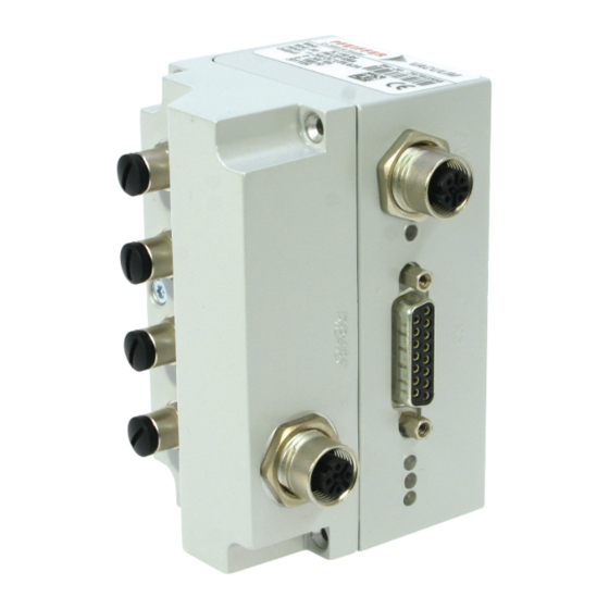
Page 14: Connectors
D-sub socket with 15 pins for connection and configuration of a remote control. RS-485 M12 bushing with screw lock for the connection of Pfeiffer Vacuum control panels or PC. The use of a Y-connector permits the integration into a bus system. -
Page 15: Installation
Installation 4 Installation 4.1 Connection diagram DANGER Danger to life from electric shock Power supply packs that are not specified or are not approved will lead to severe injury to death. ► Make sure that the power supply pack meets the requirements for double isolation between mains input voltage and output voltage, in accordance with IEC 61010-1 IEC 60950-1 and IEC 62368-1. -
Page 16: X3" Connector
RS 485 + 24 V DC** GND** RS 485 - n.c. DC in Fig. 2: Connection diagram for TC 110 RS with connection cable max. 6 mA DI Remote Priority max. 6 mA max. 6 mA n.c. Accessory A1 max. 6 mA... -
Page 17: Voltage Supply
Connection assignment of the 15-pin connection "X3" 4.2.1 Voltage supply +24 V DC input/pin 1 The electrical connection to “X3” is made using connection cable from the Pfeiffer Vacuum accessory program or, by the customer, at pin 1 and pin 15. +24 V DC* output/pin 7 A connection with +24 V DC to pin 7 (active high) activates inputs 2 to 6. -
Page 18: Outputs
The digital outputs at the “X3” connection have a maximum load limit of 24 V/50 mA per output. All out- puts listed below are configurable with the Pfeiffer Vacuum parameter set via the RS-485 interface (de- scription relates to factory settings). -
Page 19: Rs-485
Installation 4.2.4 RS-485 Connecting RS-485 via D-Sub ► Connect a Pfeiffer Vacuum control unit or an external PC via pin 13 and pin 14 at the D-Sub con- nection of the electronic drive unit. 19/50... -
Page 20: Interfaces
"RS-485" connection on TC 110 RS drive electronics. The interface with the designation “RS-485” is intended for the connection of a Pfeiffer Vacuum display and control unit (DCU or HPU) or an external computer. The connections are galvanically safe and are isolated from the maximum supply voltage for the electronic drive unit. -
Page 21: Connection Options
"DC in" power supply plug 3 RJ45 connector assembly DCU 110 - 310 4 HPU "DC in" power supply plug 5 TC 110 RS 6 D-sub plug DCU 002 7 TC 110 RS Connect display and control units ► Use connection cables from the control unit scope of delivery or from the accessories program. -
Page 22: Cross-Linked Via The Rs-485 Connection
3. Connect all devices with RS-485 D+ and RS-485 D- to the bus. 5.2 Pfeiffer Vacuum protocol for RS-485 interface 5.2.1 Telegram frame The telegram frame of the Pfeiffer Vacuum protocol contains only ASCII code characters [32; 127], the exception being the end character of the telegram C . Basically, a host (e.g. -
Page 23: Telegram Description
Interfaces 5.2.2 Telegram description Data query --> Control command --> Data response / Control command understood --> Error message --> NO_DEF Parameter number n2–n0 no longer exists _RANGE Data dn–d0 outside the permissible range _LOGIC Logical access error 5.2.3 Telegram example 1 Data query Current rotation speed (parameter [P:309], device address: "123") -->... -
Page 24: Data Types
Interfaces 5.2.5 Data types Data type Description Length Example l1 – l0 boolean_old Logical value (false/true) 000000 is equivalent to false 111111 is equivalent to true u_integer Positive whole number 000000 to 999999 u_real Positive fixed point number 001571 corresponds with 15.71 string Any character string with 6 charac-... -
Page 25: Parameter Set
Each parameter has a three-digit number and a description. The parameter can be accessed via Pfeiffer Vacuum control units or externally via RS-485 using Pfeiffer Vacuum protocol. The vacuum pump starts in standard mode with factory default pre-set parameters. - Page 26 Parameter set Display Description Functions Data Unit min. max. type cess fault type Cfg DO2 Configura- 0 = rotation speed switch point tion output reached 1 = no error 2 = error 3 = warning 4 = error and/or warning 5 = set rotation speed reached 6 = pump on 7 = pump accelerating...
- Page 27 Parameter set Display Description Functions Data Unit min. max. type cess fault type Cfg Acc A1 Configura- 0 = fan tion acces- 1 = venting valve, closed with- sory connec- out current tion A1 2 = heating 3 = backing pump 4 = fan (temperature controlled) 5 = sealing gas 6 = always "0"...
-
Page 28: Status Requests
Parameter set Display Description Functions Data Unit min. max. type cess fault type Cfg DI1 Configura- Setting ≠ [P:063] tion input 0 = deactivated 1 = enable venting 2 = heating 3 = sealing gas 4 = run-up time monitoring 5 = rotation speed mode 6 = motor 7 = enable HV sensor 1... -
Page 29: Set Value Settings
Parameter set Display Description Func- Data Access Unit min. max. tions type type fault TempMotor Temperature motor °C 999999 ElecName Name of electronic drive unit HW Version Hardware version electron- ic drive unit ErrHist1 Error code history, item 1 ErrHist2 Error code history, item 2 ErrHist3 Error code history, item 3... -
Page 30: Additional Parameters For The Control Unit
The basic parameter set is set in the electronic drive unit ex-factory. For controlling con- nected external components (e.g. vacuum measuring equipment), additional parameters (extended parameter set) are available in the corresponding Pfeiffer Vacuum control units. ● Refer to the corresponding operating instructions of the respective components. -
Page 31: Operation
Operation 7 Operation 7.1 Configuring the connections with the Pfeiffer Vacuum parameter set The electronic drive unit is pre-configured with the factory default basic functions and is ready for opera- tion. For individual requirements, you can configure most connections for the electronic drive unit with the parameter set. -
Page 32: Configure Analog Output
7.1.4 Configure accessory connections Connect accessory devices to TC 110 RS ● Use of Pfeiffer Vacuum accessories via the TC 110 RS electronic drive unit is possible via a corresponding connection cable or adapter at the “X3” multi-function connection and at the accessory connections "A1", "A2", "B1", and "B2". -
Page 33: Select Interfaces
► Make sure that the gas mode is set correctly by [P:027] in the electronic drive unit. ► Consult Pfeiffer Vacuum before you use gases with higher molecular masses (> 80). High gas throughput and high rotation speed lead to strong friction heating of the rotor. To avoid over- heating, power to rotation speed characteristics are implemented in the electronic drive unit. -
Page 34: Set Value Power Consumption
Operation P max [P:708] Fig. 6: Schematic diagram of power characteristics, example of heavy gases [P:027] = 0 Power consumption Power characteristic in gas mode "0" (gases with molecu- lar mass > 39, e.g. Argon) Rotation speed Power characteristic in gas mode "1" (gases with molecu- lar mass ≤... - Page 35 Operation Rotation speed switch point 1 [P:017] = 0 f (%) [P:701] [P:010] [P:302] Process Fig. 7: Rotation speed switch point 1 active Adjusting rotation speed switch point 1 Signal output and status parameters are based on the set value for the rotation speed switch point 1 [P:701].
-
Page 36: Rotation Speed Setting Mode
3. Check the set rotation speed (parameter [P:308] or [P:397]). 7.2.6 Standby Pfeiffer Vacuum recommends standby mode for the turbopump during process and production stops. When standby mode is active, the electronic drive unit reduces the rotation speed of the turbo pump. -
Page 37: Backing Pump Operating Modes
Fluctuations in the power consumption of idling turbopumps and varying fore-vac- uum pressures of the backing pumps require individual settings of the interval operation. Pfeiffer Vacuum recommends interval operation between 5 and 10 hPa. A pressure gauge and a dosing valve are required to set the switching thresholds. -
Page 38: Backing Pump Standby Mode
2. Use this signal for the control of a fore-vacuum safety valve. 7.2.9 Backing pump standby mode In case you are using a Pfeiffer Vacuum backing pump with rotation speed control, this can be used in standby mode by configuring the digital output [P:019] or [P:024]. The power consumption of the turbo- pump has a direct influence on the rotation speed of the backing pump. -
Page 39: 11Venting Modes
Operation Configuring the bottom part heating The accessory output controls the heating cartridges that maintain the bottom part of the turbopump at maximum temperature. The control is carried out according to pump-specific requirements, depending on the current power input of the vacuum pump and the switch point. 1. -
Page 40: Operation Monitoring
7.5.1 Operating mode display via LED LEDs on the electronic drive unit show the basic operating states of the vacuum pump. A differentiated error and warning display is only possible for operation with the Pfeiffer Vacuum control unit or a PC. Symbol... -
Page 41: Recycling And Disposal
● Help to reduce the wastage of natural resources. ● Prevent contamination. 8.1 General disposal information Pfeiffer Vacuum products contain materials that you must recycle. ► Dispose of our products according to the following: – Iron – Aluminium –... -
Page 42: Malfunctions
Warnings (* Warning F –––– *) do not cause components to be switched off. Handling malfunction messages 1. Read out error codes via Pfeiffer Vacuum control units or a PC. 2. Remove the cause of the malfunction. 3. Reset the malfunction message with parameter [P:009]. - Page 43 Malfunctions Error Problem Possible causes Remedy code Err043 Internal configuration er- ● Device defective ● Contact Pfeiffer Vacuum Service. Err044 Excess temperature, ● Insufficient cooling ● Improve the cooling electronics ● Check the operating conditions Err045 Excess temperature, ● Insufficient cooling ●...
- Page 44 Problem Possible causes Remedy code Err810 Internal configuration er- ● Incompatible software ver- ● Contact Pfeiffer Vacuum Service. sion ● Only acknowledge for rotational speed f = 0 Err815 Magnetic bearing over- ● Impacts, vibrations ● Contact Pfeiffer Vacuum Service.
-
Page 45: Warning And Malfunction Messages When Operating With Control Units
Malfunctions Error Problem Possible causes Remedy code Wrn115 Pump lower part tem- ● Device defective ● Contact Pfeiffer Vacuum Service. perature evaluation faulty Wrn116 Bearing temperature ● Device defective ● Contact Pfeiffer Vacuum Service. evaluation faulty Wrn117 Pump lower part high ●... -
Page 46: Service Solutions By Pfeiffer Vacuum
We are always focused on perfecting our core competence – servicing of vacuum components. Once you have purchased a product from Pfeiffer Vacuum, our service is far from over. This is often exactly where service begins. Obviously, in proven Pfeiffer Vacuum quality. - Page 47 Service solutions by Pfeiffer Vacuum 5. Prepare the product for transport in accordance with the provisions in the contamination declaration. a) Neutralize the product with nitrogen or dry air. b) Seal all openings with blind flanges, so that they are airtight.
-
Page 48: Ec Declaration Of Conformity
This declaration of conformity has been issued under the sole responsibility of the manufac- turer. Declaration for product(s) of the type: Electronic drive unit TC 110 RS We hereby declare that the listed product satisfies all relevant provisions of the following European Directives. Low voltage 2014/35/EC... -
Page 49: Declaration Of Conformity
Semi F47-0200 EN IEC 61326-1:2021 Semi S2-0706 The manufacturer's authorized representative in the United Kingdom and the authorized agent for compiling the technical documentation is Pfeiffer Vacuum Ltd, 16 Plover Close, In- terchange Park, MK169PS Newport Pagnell. Signature: Pfeiffer Vacuum GmbH Berliner Straße 43...
Need help?
Do you have a question about the TC 110 RS and is the answer not in the manual?
Questions and answers