
Related Manuals for Pfeiffer Vacuum TC 1200 E74


Summary of Contents for Pfeiffer Vacuum TC 1200 E74
- Page 1 OPERATING INSTRUCTIONS Translation of the Original TC 1200 E74 Electronic drive unit...
-
Page 2: Telegram Example
Dear Customer, Thank you for choosing a Pfeiffer Vacuum product. Your new turbopump is designed to support you by its performance, its perfect operation and without interfering your individual application. The name Pfeiffer Vacuum stands for high-quality vacuum technology, a comprehensive and complete range of top-quality products and first-class service. -
Page 3: Table Of Contents
Control commands Status requests Reference value inputs Additional parameters for the control unit Operation Configuring the connections with the Pfeiffer Vacuum parameter set 7.1.1 Configuring connection "E74" 7.1.2 Configuring the accessory connections 7.1.3 Select interfaces Operating modes 7.2.1 Gas type-dependent operation... - Page 4 Switching off the turbopump Operation monitoring 7.5.1 Operating mode display via LED 7.5.2 Temperature monitoring Malfunctions General Error codes Warning and malfunction messages when operating with control units Service solutions by Pfeiffer Vacuum EC Declaration of Conformity UK Declaration of Conformity 4/48...
- Page 5 List of tables List of tables Tbl. 1: Product labels Tbl. 2: Abbreviations used in this document Tbl. 3: Permissible ambient conditions Tbl. 4: Features of the device variant Tbl. 5: Delivered drive power depending on the supplied mains voltage Tbl.
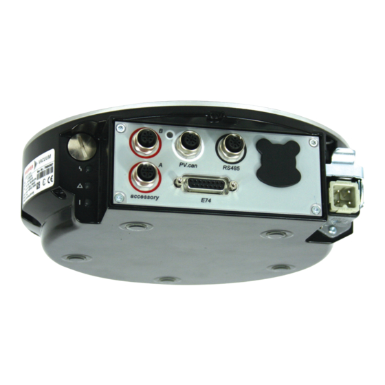
- Page 6 List of figures List of figures Fig. 1: Connection panel TC 1200 E74 Fig. 2: Diagram and assignments of the connection panel Fig. 3: Connecting RS-485 devices Fig. 4: Interface "E74" Fig. 5: Networking of several electronic drive units in RS-485 Bus Fig.
-
Page 7: About This Manual
Keep the manual for future consultation. 1.1 Validity This operating instructions is a customer document of Pfeiffer Vacuum. The operating instructions de- scribe the functions of the named product and provide the most important information for the safe use of the device. The description is written in accordance with the valid directives. The information in this op- erating instructions refers to the product's current development status. -
Page 8: Product Labels
Meaning in this document AI / AO Analog Input / Analog Output Ampere Interrupting Capacity Display Control Unit (Pfeiffer Vacuum display and control unit) DI / DO Digital Input / Digital Output Version in compliance with SEMI E74 Rotation speed value of a vacuum pump (frequency, in rpm or Hz) Handheld Programming Unit. -
Page 9: Safety
Safety 2 Safety 2.1 General safety information The following 4 risk levels and 1 information level are taken into account in this document. DANGER Immediately pending danger Indicates an immediately pending danger that will result in death or serious injury if not observed. ►... -
Page 10: Safety Precautions
Safety DANGER Danger to life from electric shock Power supply packs that are not specified or are not approved will lead to severe injury to death. ► Make sure that the power supply pack meets the requirements for double isolation between mains input voltage and output voltage, in accordance with IEC 61010-1 IEC 60950-1 and IEC 62368-1. -
Page 11: Limits Of Use Of The Product
Safety Infringement of conformity due to modifications to the product The Declaration of Conformity from the manufacturer is no longer valid if the operator changes the original product or installs additional equipment. ● Following the installation into a system, the operator is required to check and re-evalu- ate the conformity of the overall system in the context of the relevant European Direc- tives, before commissioning that system. -
Page 12: Proper Use
Safety 2.5 Proper use ● The electronic drive unit is used exclusively for the operation of Pfeiffer Vacuum turbopumps and their accessories. 2.6 Foreseeable misuse Improper use of the product invalidates all warranty and liability claims. Any use that is counter to the purpose of the product, whether intentional or unintentional, is regarded as misuse, in particular: ●... -
Page 13: Product Description
ID no. 000021320. 3.2 Product features The electronic drive unit of type TC 1200 E74 represents a fixed component of the Turbopump. The purpose of the electronic drive unit is to drive, monitor and control the entire turbopump. The electronic drive unit is equipped with an integrated extended voltage supply. -
Page 14: Scope Of Delivery
D-Sub socket with 15 pins for the connection and configuration of a remote control in compliance with SEMI E74. RS-485 M12 socket with screw lock for the connection of Pfeiffer Vacuum control panels or PC. The use of a Y-distributor permits the integration into a bus system. Tbl. 6: Connection description of the electronic drive unit The "accessory"... -
Page 15: Installation
Installation 4 Installation 4.1 Connecting diagram DANGER Danger to life from electric shock Power supply packs that are not specified or are not approved will lead to severe injury to death. ► Make sure that the power supply pack meets the requirements for double isolation between mains input voltage and output voltage, in accordance with IEC 61010-1 IEC 60950-1 and IEC 62368-1. - Page 16 Installation n.c. n.c. Accessory A2 Accessory B2 24 V DC** 24 V DC** Accessory A1 Accessory B1 start / stop (+) AO1 (-) CAN-H acceleration status (+) 24 V DC*** normal status (+) GND*** deceleration status (+) CAN-L alarm staus (+) remote / local status (+) ~ alarm status (+) start / stop (-)
-
Page 17: Connection "E74
Installation 4.2 Connection "E74" Besides the signals defined in the Directive SEMI E74-0301, connection "E74" with 15-pin female con- nector is provided with an inverted alarm signal and an analog output. Assignment start/stop (+) AO1 (-) acceleration status (+) normal status (+) deceleration status (+) alarm status (+) remote/local status (+) -
Page 18: Mains Power Supply
Installation Fig. 3: Connecting RS-485 devices 1 USB/RS-485 converter Control unit with power supply pack 2 PC RS-485 interface connection 3 Electronic drive unit Connecting RS-485 devices One external control unit each can be connected at the RS-485 interface. 1. Use corresponding connection cables from the control unit scope of delivery or from the range of accessories. -
Page 19: Tbl. 9: Terminal Lay-Out Of The Power Supply Connector
Terminal lay-out of the power supply connector Establishing mains connection 1. Order a corresponding power supply cable from the Pfeiffer Vacuum accessories range. 2. Assemble your own power supply cable using the HAN 3A connecting socket from the shipment. 3. Plug mains cable into the mains connection "AC in". -
Page 20: Interfaces
Interfaces 5 Interfaces 5.1 Interface E74 The signal (-) lines of the "alarm status (+)" and "~alarm status (+)" are grouped for the "alarm status (-)" signal. Input signal Output signal signal (+) signal (+) signal (-) signal (-) Fig. 4: Interface "E74" 5.1.1 Signal description Signal Pins... -
Page 21: Tbl. 12: Features Of The Rs-485 Interface
Interfaces maximum supply voltage for the electronic drive unit. The electrical connections are optically decoupled internally. Designation Value Serial interface RS-485 Baud rate 9600 Baud Data word length 8 bit Parity none (no parity) Start bits Stop bits Tbl. 12: Features of the RS-485 interface Assignment RS-485 D+... -
Page 22: Pfeiffer Vacuum Protocol For Rs-485 Interface
Interfaces 5.3 Pfeiffer Vacuum protocol for RS-485 interface 5.3.1 Telegram frame The telegram frame of the Pfeiffer Vacuum protocol contains only ASCII code characters [32; 127], the exception being the end character of the telegram C . Basically, a host (e.g. a PC) sends a tele- gram, which a device (e.g. -
Page 23: Data Types
Interfaces 5.3.4 Telegram example 2 Control command Switch on the pumping station (parameter [P:010], device address: "042" --> ASCII Control command understood Switch on the pumping station (parameter [P:010], device address: "042" --> ASCII 5.3.5 Data types Data type Description Length Example l1 –... -
Page 24: Parameter Set
Each parameter has a three-digit number and a description. The parameter can be accessed via Pfeiffer Vacuum control units or externally via RS-485 using Pfeiffer Vacuum protocol. The vacuum pump starts in standard mode with factory default pre-set parameters. - Page 25 Parameter set Display Description Functions Data Unit min. max. type cess fault type Cfg DO2 Output DO2 0 = Rotation speed switchpoint configuration reached 1 = No error 2 = Error 3 = Warning 4 = Error and/or warning 5 = Set rotation speed reached 6 = Pump on 7 = Pump accelerating 8 = Pump decelerating...
- Page 26 Parameter set Display Description Functions Data Unit min. max. type cess fault type Cfg Acc A1 Configuration 0 = fan (continuous operation) accessory 1 = Venting valve, closed with- connection out current 2 = Heating 3 = Backing pump 4 = Fan (temperature control- led) 5 = Sealing gas 6 = Always "0"...
-
Page 27: Status Requests
Parameter set Display Description Functions Data Unit min. max. type cess fault type CtrlViaInt Operate via 1 = remote interface 2 = RS-485 4 = PV.can 8 = Fieldbus 16 = E74 255 = Unlock interface selec- tion IntSelLckd Interface se- 0 = off lection locked 1 = on... -
Page 28: Reference Value Inputs
Parameter set Display Description Func- Data Access Unit min. max. tions type type fault OpHrsElec Drive electronics operating 65535 hours Nominal Spd Nominal rotation speed 999999 (Hz) DrvPower Drive power 999999 PumpCycles Pump cycles 65535 TempPwrStg Final stage temperature °C 999999 TempElec Electronics temperature... -
Page 29: Additional Parameters For The Control Unit
The basic parameter set is set in the electronic drive unit ex-factory. For controlling con- nected external components (e.g. vacuum measuring equipment), additional parameters (extended parameter set) are available in the corresponding Pfeiffer Vacuum control units. ● Refer to the corresponding operating instructions of the respective components. - Page 30 Parameter set Indicator Description Functions Data Access Unit min. max. type type fault Param set Parameter set 0 = Basic pa- rameter set 1 = Extended parameter set Servicelin Insert service line Tbl. 18: Parameters for control unit functions 30/48...
-
Page 31: Operation
Operation 7 Operation 7.1 Configuring the connections with the Pfeiffer Vacuum parameter set The electronic drive unit is pre-configured with the factory default basic functions and is ready for opera- tion. For individual requirements, you can configure most connections for the electronic drive unit with the parameter set. -
Page 32: Select Interfaces
► Make sure that the gas mode is set correctly by [P:027] in the electronic drive unit. ► Consult Pfeiffer Vacuum before you use gases with higher molecular masses (> 80). High gas throughput and high rotation speed lead to strong friction heating of the rotor. To avoid over- heating, power to rotation speed characteristics are implemented in the electronic drive unit. -
Page 33: Set Value Power Consumption
Operation P max [P:708] Fig. 6: Schematic diagram of power characteristics, example of heavy gases [P:027] = 0 Power consumption Power characteristic in gas mode "0" (gases with molecu- lar mass > 39, e.g. Argon) Rotation speed Power characteristic in gas mode "1" (gases with molecu- lar mass ≤... - Page 34 Operation Rotation speed switch point 1 [P:017] = 0 f (%) [P:701] [P:010] [P:302] Process Fig. 7: Rotation speed switch point 1 active Adjusting rotation speed switch point 1 Signal output and status parameters are based on the set value for the rotation speed switch point 1 [P:701].
-
Page 35: Rotation Speed Setting Mode
3. Check the set rotation speed (parameter [P:308] or [P:397]). 7.2.6 Standby Pfeiffer Vacuum recommends standby mode for the turbopump during process and production stops. When standby mode is active, the electronic drive unit reduces the rotation speed of the turbo pump. -
Page 36: Backing Pump Operating Modes
Fluctuations in the power consumption of idling turbopumps and varying fore-vac- uum pressures of the backing pumps require individual settings of the interval operation. Pfeiffer Vacuum recommends interval operation between 5 and 10 hPa. A pressure gauge and a dosing valve are required to set the switching thresholds. -
Page 37: Backing Pump Standby Mode
2. Use this signal for the control of a fore-vacuum safety valve. 7.2.9 Backing pump standby mode In case you are using a Pfeiffer Vacuum backing pump with rotation speed control, this can be used in standby mode by configuring the digital output [P:019] or [P:024]. The power consumption of the turbo- pump has a direct influence on the rotation speed of the backing pump. -
Page 38: Switching On The Turbopump
7.5.1 Operating mode display via LED LEDs on the electronic drive unit show the basic operating states of the vacuum pump. A differentiated error and warning display is only possible for operation with the Pfeiffer Vacuum control unit or a PC. 38/48... -
Page 39: Temperature Monitoring
Operation Symbol LED status Display Meaning Currentless On, flashing "pumping station OFF", rotation speed ≤ 60 rpm Green On, inverse flashing "pumping station ON", set rotation speed not reached On, constant "pumping station ON", set rotation speed reached On, flashing "pumping station OFF", speed >... -
Page 40: Malfunctions
Warnings (* Warning F –––– *) do not cause components to be switched off. Handling malfunction messages 1. Read out error codes via Pfeiffer Vacuum control units or a PC. 2. Remove the cause of the malfunction. 3. Reset the malfunction message with parameter [P:009]. - Page 41 Malfunctions Error Problem Possible causes Remedy code Err043 Internal configuration er- ● Device defective ● Contact Pfeiffer Vacuum Service Err044 Excess temperature, ● Insufficient cooling ● Improve the cooling electronics ● Check the operating conditions Err045 Excess temperature, ● Insufficient cooling ●...
- Page 42 Problem Possible causes Remedy code Err800 Magnetic bearing over- ● Impacts, vibrations ● Contact Pfeiffer Vacuum Service flow ● Device defective ● Check the operating conditions ● Only acknowledge for rotational speed f = 0 Err802 Magnetic bearing sen- ● Calibration values invalid ●...
-
Page 43: Warning And Malfunction Messages When Operating With Control Units
● Check the operating conditions ● Impermissible thermal radiation ● Impermissible magnetic field Wrn113 Inaccurate rotor tem- ● Internal communication error ● Contact Pfeiffer Vacuum Service perature Wrn115 Pump lower part tem- ● Device defective ● Contact Pfeiffer Vacuum Service... -
Page 44: Service Solutions By Pfeiffer Vacuum
We are always focused on perfecting our core competence – servicing of vacuum components. Once you have purchased a product from Pfeiffer Vacuum, our service is far from over. This is often exactly where service begins. Obviously, in proven Pfeiffer Vacuum quality. - Page 45 Service solutions by Pfeiffer Vacuum 5. Prepare the product for transport in accordance with the provisions in the contamination declaration. a) Neutralize the product with nitrogen or dry air. b) Seal all openings with blind flanges, so that they are airtight.
-
Page 46: Ec Declaration Of Conformity
This declaration of conformity has been issued under the sole responsibility of the manufac- turer. Declaration for product(s) of the type: Electronic drive unit TC 1200 E74 We hereby declare that the listed product satisfies all relevant provisions of the following European Directives. Electromagnetic compatibility 2014/30/EU... -
Page 47: Declaration Of Conformity
Semi F47-0200 EN IEC 61326-1:2021 Semi S2-0706 The manufacturer's authorized representative in the United Kingdom and the authorized agent for compiling the technical documentation is Pfeiffer Vacuum Ltd, 16 Plover Close, In- terchange Park, MK169PS Newport Pagnell. Signature: Pfeiffer Vacuum GmbH Berliner Straße 43...
Need help?
Do you have a question about the TC 1200 E74 and is the answer not in the manual?
Questions and answers