Advertisement
Quick Links
Cod. 6328224 - 02/2024 - R1
MURELLE
70 BOX ErP
USER, INSTALLATION AND SERVICING INSTRUCTIONS
USER, INSTALLATION AND SERVICING INSTRUCTIONS
ENSURE THAT THESE
INSTRUCTIONS ARE LEFT
FOR THE USER AFTER
COMPLETION OF THE
BENCHMARK SECTION
PLEASE READ THE
IMPORTANT NOTICE
WITHIN THIS GUIDE
REGARDING YOUR BOILER
WARRANTY
199839
ORIGINAL INSTRUCTIONS
Advertisement

Related Manuals for Sime MURELLE 70 BOX ErP


Summary of Contents for Sime MURELLE 70 BOX ErP
- Page 1 Cod. 6328224 - 02/2024 - R1 MURELLE 70 BOX ErP USER, INSTALLATION AND SERVICING INSTRUCTIONS USER, INSTALLATION AND SERVICING INSTRUCTIONS ENSURE THAT THESE INSTRUCTIONS ARE LEFT FOR THE USER AFTER COMPLETION OF THE BENCHMARK SECTION PLEASE READ THE IMPORTANT NOTICE WITHIN THIS GUIDE REGARDING YOUR BOILER WARRANTY...
- Page 2 – Use a suitable container to catch any water that escape when removing the protective caps from the connections. MURELLE 70 BOX ErP: Gas Council number 47-283-88 CONFORMITY Our Company declares that MURELLE 70 BOX ErP boilers comply with the essential requirements of the following directives: - Boiler Efficiency Directive 92/42/EEC...
-
Page 3: Table Of Contents
CONTENTS DEVICE DESCRIPTION ..............pag. INSTALLATION . -
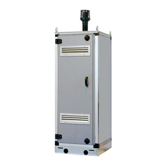
Page 4: Device Description
MURELLE 70 BOX ErP heat modules are lation thanks to the galvanised sheet metal, DIMENSIONS MODULES (fig. 1) FIXTURES System supply R 2” (UNI - ISO 7/1) System return R 2”... - Page 5 TECHNICAL SPECIFICATIONS MURELLE 70 BOX ErP Heat output Nominal (80-60°C) (Pn max) 63.2 Nominal (50-30°C) (Pn max) 68.1 Minimum (80-60°C) (Pn min) 13.4 Minimum (50-30°C) (Pn min) 15.0 Heat input (*) Nominal (Qn max - Qnw max) 65.0 Minimum (Qn min - Qnw min) 14.0...
- Page 6 The boiler (29) shall be controlled through the RVS control unit (configure the instal- ler parameter PAR 10). Only if the Murelle 70 BOX ErP is to be Murell e HE 50 R ErP MURELLE 70 BOX ErP installed indoors when the boiler (29) is...
- Page 7 MAIN COMPONENTS (fig. 3) Code 8111234 Model MURELLE 70 BOX ErP Serial n. 9999999999 PAR 1 = 60 (G20) / 62 (G31) PAR 2 = 9 1 Control panel 2 100°C Safety thermostat 3 Heating supply probe (SM) 4 Ignition transformer...
- Page 8 TECHNICAL DATA PLATE (fig. 3/a) MODEL TYPE SERIAL NUMBER CODE YEAR OF CONSTRUCTION PIN NUMBER DIRECTIVE OF REFERENCE WATER CONTENT IN BOILER HEAT INPUT MAX HEAT INPUT MIN HEAT OUTPUT MAX (80-60°C) HEAT OUTPUT MIN (80-60°C) HEAT OUTPUT MAX (50-30°C) HEAT OUTPUT MIN (50-30°C) MAX OPERATING PRESSURE MAX OPERATING PRESSURE...
-
Page 9: Installation
Condensation drain connection in a fixed location. It must be installed by qualified engineers MURELLE 70 BOX ErP heat modules can The condensate drain must be connected in compliance with all instructions con- also be installed outdoors with the specific to the civil drain by a pipe with minimum 5 tained in this manual. - Page 10 MURELLE 110-92.5 BOX ErP con kit c ollettor e fumi The indicated solutions have the exhaust manifold positioned both on the modules. cod. 8102510 It is however possible to move the exhaust of the left by simply rotating the manifold ¿...
- Page 11 3 A. PORTATA (m BOILER SIDE SIDE HEATING SYSTEM LATO CALDAI A NOTE: Sime declines all responsibility LATO IMPIANT O for injury or damage to persons, animals or property resulting from the failure to Fig. 10 provide for proper earthing of the appli-...
- Page 12 Fuse (4 AT) Zone 2 environment thermostat PART CODES: Ignition transformer SB/SA Antifreeze siphon sensor Pump high efficiency Remote control code 6319162 SIME HOME (optional) code 6323824 Ignition electrode External sensor (optional) code 6319164 Ionisation electrode Programming clock (optional) code 6316203 EV1-2...
- Page 13 2.9.3 Remote control SIME HOME connection (optional) The heating demand can be controlled by use of remote control unit SIME HOME (code 8092280/81) The remote control unit allows for com- plete control, except lockout reset. The generator will display CR.
-
Page 14: Characteristics
(access to INST and OEM parameters) OFF = Electricity supply to boiler is on but nor ready To be used only with the SIME programming kit and for functioning. However, the protection only by authorised personnel. Do not connect other functions are active. - Page 15 ACCESS TO INSTALLER’S INFORMATION For access to information for the installer, press the key (3 fig. 12). Every time the key is pressed, the display moves to the next item of information. If the key is not pressed, the system automatically quits the function. If there is no expansion board (MIXED ZONE or SOLAR) the relative info will not be displayed.
- Page 16 18. Display of Heating return sensor value (SR) Display of valve closing opening control with board Visualizzazione valore sonda ritorno riscaldamento (SR) Visualizzazione comando chiusura valvola con schedino MIXED ZONE 2 (respectively ON and OFF) ZONA MIX 2 (rispettivamente ON e OFF) 30.
- Page 17 1 = Enabled matically after 60 seconds, or by pressing Allocation of SIME HOME channels 0 = Not assigned atore in h x 100 (es. 14.000 e 10) 1 = Circuit 1 one of the control keys (2 fig. 12).
- Page 18 BOILER PAR 2 PARAMETERS INSTALLER Instantaneous with diverter valve and flowmeter EXPANSION CARD Instantaneous with diverter valve PAR DESCRIPTION RANGE UNIT OF INC/DEC DEFAULT flowmeter and solar combination MEASUREMENT UNIT SETTING Remote control DHW cylinder Number of expansion boards 0 ... 3 with diverter valve and cylinder Mix valve stroke time 0 ...
- Page 19 Temperature (°C) Resistance (Ω) – Interface with the following electronic 12.090 – Lack of gas systems: remote control SIME HOME 8.313 code 8092280/81, thermal regulator The ignition electrode persists in dis- 5.828 RVS, connected to a management card charging for max.
-
Page 20: Commissionimg, Use And Maintenance
“Chimney Sweep “mode as working gas supply pressure. requirements of table 1.3. described in section 4.5.1 and If required contact Sime Ltd for Ensure that this inlet pressure record the measurements from further assistance. can be obtained with all other... - Page 21 The generator is supplied as standard with a gas valve, model SIT 822 NOVAMIX (fig. 16). GAS CONVERSION This operation must be performed by authorised personnel using original Sime Upstream pressure intake components. Intermediate pressure intake Air signal inlet (VENT)
- Page 22 able before activating chimney sweep). If the key are pressed during the 15 minutes of the chimney sweep func- tion, the boiler will be brought respectively to maximum and minimum power. The chimney sweep function will automat- ically switch off after 15 minutes or when the key is pressed again.
- Page 23 FUNCTIONING ERRORS Apre When there is a functioning error, an alarm Circuito Circuito riscaldamento 2 appears on the display and the blue lumi- riscaldamento 2 nous bar becomes red. Descriptions of the errors with relative alarms and solutions are given below: Circuito riscaldamento 2 –...
- Page 24 Apre – SAFETY/LIMIT THERMOSTAT ERROR ALARM 07 (fig. 23/6) If either the 95 degree stat or the heat Circuito exchanger safety stat opens, the burner riscaldamento 2 will turn off and ALL 07 will be displayed. Press the key of the controls (2) to start up the boiler again.
- Page 25 (impianto tre zone) ircuito – “ALL 15” FAN ERROR (fig. 23/12) – SAFETY THERMOSTAT INTERVENTION – AUXILIARY SENSOR ANOMALY (S3) iscaldamento 2 Circuito The fan speed does not fall within the SECOND MIXED ZONE “ALL 22” (fig. “ALL 26” (fig. 23/20) riscaldamento 2 rated speed range.
- Page 26 CAUTION: In the event of sequence/cas- Apre The boiler restarts when the boiler cade connection, error codes 70 and 71 three-zone system configuration is acti- will appear on the SIME HOME remote vated. control display: - ALARM 70 When an anomaly affects cascade oper-...
- Page 27 SERVICE & INTERIM BOILER WORK RECORD It is recommended that your boiler and heating system are regularly serviced and maintained, in line with manufacturers’ instructions, and that the appropriate service / interim work record is completed. Service provider When completing a service record (as below), please ensure you have carried out the service as described in the manufacturers’ instructions. Always use the SERVICE/INTERIM WORK ON BOILER SERVICE/INTERIM WORK ON BOILER Date:...
- Page 28 SERVICE & INTERIM BOILER WORK RECORD It is recommended that your boiler and heating system are regularly serviced and maintained, in line with manufacturers’ instructions, and that the appropriate service / interim work record is completed. Service provider When completing a service record (as below), please ensure you have carried out the service as described in the manufacturers’ instructions. Always use the SERVICE/INTERIM WORK ON BOILER SERVICE/INTERIM WORK ON BOILER Date:...
-
Page 31: Fault Finding
FAULT FINDING If an electrical fault occurs on the appli- reads 0 then there is a short circuit. scale. ance the preliminary electrical system Meter set on ø (ohm) x 100 scale. Repeat All switches including thermostat on test checks must be carried out first. it with leads from L to E. - Page 32 APPENDIX 1 Manufacturer's Instructions The latest manufacturer’s instructions shall be followed for the correct connection of the condensate discharge pipe from the boiler as this may vary due to the design of the boiler. For example, a trap is not required in the condensate discharge pipework if there is a trap with a minimum condensate seal of 75 mm incorporated into the boiler.
- Page 33 Figure 1 – Connection of condensate discharge pipe to internal soil and vent stack. Note – Refer to manufacturer’s instructions Boiler Minimum internal diameter 19 mm Soil and vent stack 450 mm minimum up to three storeys Invert Manufacturers Instructions shall be referred to when installing boiler condensate discharge pipes...
- Page 34 Internal Condensate Pipe Connection with External Termination Figure 2(a) – Connection of a condensate discharge pipe downstream of a sink, basin, bath or shower waste trap. Note – Check manufacturer’s instructions to see if an air break or trap is required. Boiler Visible air break 75 mm trap...
- Page 35 Internal Condensate Pipe Connection with External Termination Figure 2(b) – Connection of a condensate discharge pipe downstream of a sink, basin, bath or shower waste trap Boiler Visible air break at plug hole – 75 mm sink, basin, bath or shower waste trap Sink, basin, bath or shower with integral overflow Open end of condensate discharge pipe direct into gully 25 mm min below grating but above water level;...
- Page 36 Internal Condensate Pipe Discharge Termination When connecting to existing pipework it is critical to review the existing installation to ensure the existing pipework is appropriate for condensate discharge having been run correctly and fully insulated and sealed if this is an external or internal termination. The possibility of waste pipes freezing downstream of the connection point shall be con- sidered when determining a suitable connection point - e.g.
- Page 37 External Connections External Connections External Connections Only fit a correctly insulated external boiler condensate drain connection if an internal gravity or pumped connection is impractical to install. The pipe work from the boiler shall be of a minimum 19mm ID or if in an unheated area increased to 30mm ID (typically 32mm OD) solvent weld of as per manufacturer’s instructions and the condensate discharge pipe shall be run in a standard drainpipe material, e.g.
- Page 38 External Connections Figure 3 – Connection of condensate discharge pipe to external soil and vent stack Boiler Internal Trap Visible air break and trap not required if there is a trap with a minimum condensate seal of 75mm incorporated into the boiler. Soil and vent stack Invert 450mm minimum up to three storeys...
- Page 39 External Connections onnecting to a rain water downpipe/External Soil Stack When a rain water downpipe is used as the termination (NB only permissible if this downpipe passes to a combined foul and rainwater drainage system) an external air break shall be installed between the condensate discharge pipe and the downpipe to avoid reverse flow of rainwater into the boiler should the downpipe itself become blocked, flooded or frozen.
- Page 40 External Connections Figure 4 – External termination to rainwater downpipe (NB only combined foul/rainwater drain) Condensate discharge pipe from boiler Pipe size transition point Water/weather proof, UV resistant insulation 43mm 90° male/female bend External rain water pipe into foul water External air break Air gap 68mm PVCu strap on fitting...
- Page 41 External Connections Figure 5 – Preferred Method: External drain, gully or rainwater hopper Boiler Visible air break 38mm minimum trap Visible air break and trap not required if there is a trap with a minimum condensate seal of 38 mm incorporated into the boiler – refer to manufacturer's instructions External length of pipe 3 m maximum Open end of condensate discharge pipe direct into gully 25 mm min below grating but above water level;...
- Page 42 External Connections Figure 6 – Example of a purpose made soakaway Condensate discharge pipe from boiler Ground (this section of the condensate discharge pipe may be run either above or below round level); End cut at 45° Diameter 100 mm minimum plastic tube Bottom of tube sealed Limestone chippings Two rows of three 12 mm holes at 25 mm centres, 50 mm from bottom of tube and facing...
- Page 43 Other considerations Unheated Areas in Buildings Internal condensate drainage pipes run in unheated areas such as lofts, basements and garages shall be treated as external connections and insulated accordingly. Weather proof materials may not be necessary but where separate sections of insulation join together, including elbow joints then these should be connected, insulated and sealed correctly to prevent them coming apart with a suitable material to help prevent freezing.
- Page 44 Alternative Solutions Cold weather protection Cold weather protection methods approved or endorsed by boiler manufacturers and/ or service organisations may be adopted if these are considered suitable by the parties involved. It is the responsibility of the manufacturer of these products to ensure they have completed the necessary testing or calculations to ensure the product offers suitable protection to prevent the condensate pipe from freezing.
- Page 45 Annex A Annex A Note – Annex A details remedial actions for householders which can be taken if a condensate discharge pipe freezes. This may result in requests for alter- ation to condensate discharge pipework, in which case the guidance above should be followed.
- Page 46 Annex A Your Engineer has identified the potential for your boiler to freeze in extreme conditions as the following: Risk category Explanation Engineer selection High risk of freezing- TAKE ACTION AMBER Medium risk of freezing- Strongly advise action to be taken GREEN Low risk but some improvement required...
- Page 47 Annex A Customer advice in extreme cold weather conditions Thawing Frozen Condensate Pipes Below is an explanation of what you would need to do to resolve the problem in the event that the pipe was to freeze. We would highly recommend getting a professional to assess the situation and resolve the problem by upgrading the condensate.
-
Page 49: User Instructions
USER INSTRUCTIONS Apre IGNITION (fig. 24) The first ignition of the boiler must be carried out by qualified technical person- nel. Successively, if it is necessary to start up the boiler again, adhere strictly to the following instructions: open the gas tap Circuito to allow the flow of the fuel and move the riscaldamento 2... - Page 50 – ALL 70 and ALL 71 and, if low temperatures are expected, to If the anomaly persists, request assi- These alarms appear on the SIME completely empty the hydraulic circuits stance from qualified technical per- HOME remote control display. Re- Apre to avoid pipes being damaged by frost.
-
Page 51: Product Details
PRODUCT DETAILS Murelle Equipe 140 BOX ErP Murelle 70 BOX ErP Classe efficienza energetica stagionale riscaldamento Clase de eficiencia energética estacional en calefacción Classe de eficiência energética do aquecimento ambiente sazonal C.H. energy efficiency class Potenza termica (kW) Potencia térmica (kW) Potência calorífica (kW) - Page 52 Daily fuel consumption Recapiti / Datos de contacto Fonderie Sime S.p.A. Via Garbo 27, 37045 Legnago (VR) ITALIA Elementos de contacto / Contact details a. Regime ad alta temperatura: temperatura di ritorno di 60°C all’entrata e 80°C di temperatura di fruizione all’uscita dell’apparecchio b.
- Page 53 NOTES...
- Page 56 Sime Ltd 1a Blue Ridge Park Thunderhead Ridge Glasshoughton, Castleford, WF10 4UA Phone: 0345 901 1114 Fax: 0345 901 1115 www.sime.co.uk Email: enquiries@sime.co.uk...
Need help?
Do you have a question about the MURELLE 70 BOX ErP and is the answer not in the manual?
Questions and answers