Table of Contents
Advertisement
Quick Links
ISTRUZIONI PER L'INSTALLAZIONE E LA MANUTENZIONE
Gentile Cliente,
metta in funzione la sua nuova caldaia entro 30gg dalla data di installazione. Potrà così
beneficiare, oltre alla garanzia legale, anche della garanzia convenzionale Sime riportata
in questo manuale.
Fonderie SIME S.p.A
SOLIDA EV
RO
IT
RUS
PT
FR
ES
DE
ENG
Cod. 6113718A - 10/2018
SL
Advertisement
Table of Contents

Subscribe to Our Youtube Channel
Related Manuals for Sime SOLIDA EV 3


Summary of Contents for Sime SOLIDA EV 3
- Page 1 ISTRUZIONI PER L’INSTALLAZIONE E LA MANUTENZIONE Gentile Cliente, metta in funzione la sua nuova caldaia entro 30gg dalla data di installazione. Potrà così beneficiare, oltre alla garanzia legale, anche della garanzia convenzionale Sime riportata in questo manuale. Fonderie SIME S.p.A...
- Page 2 INDEX MAIN WARNINGS............................. SUPPLY................................DIMENSIONAL TECHNICAL CHARACTERISTICS................... . 3.1. DESCRIPTION 3.2. OVERALL.DIMENSIONS 3.3. TECHNICAL.DATA 3.4. PRESSURE.DROP INSTALLATION..............................4.1. BOILER.ROOM 4.2. CONNECTION.TO.THE.CHIMNEY 4.3. CONNECTION.TO.THE.SYSTEM 4.4. ASSEMBLING.THE.ACCESSORIES 4.5. ASSEMBLING.THE.CASING 4.6. DRAUGHT.REGULATOR 4.7. SAFETY.EXCHANGER 4.8. HYDRAULIC.CONNECTION.DIAGRAMS USE AND MAINTENANCE..........................
-
Page 3: Main Warnings
MAIN WARNINGS The. instruction. manual. is. an. integral. part. Ensure.that.the.product.is.intact..In.case.of. cal. personnel.. Any. repair. must. be. carried. of.the.product.and.must.be.delivered.to.the. doubt,.do.not.use.the.appliance.and.contact. out.by.using.original.spare.parts.only. user.. Carefully. read. the. warnings. contai- the.supplier..Packaging.components.must. ned.in.the.manual.on.installation,.use.and. be.disposed.of.in.compliance.with.the.stan- Failure.to.comply.with.that.above.can.com- maintenance. of. the. appliance.. Carefully. dards.in.force. promise.the.integrity.of.the.system.and.sin- store.the.manual.for.future.reference. gle. components,. being. a. potential. danger. Before. -
Page 4: Technical And Dimensional Characteristics
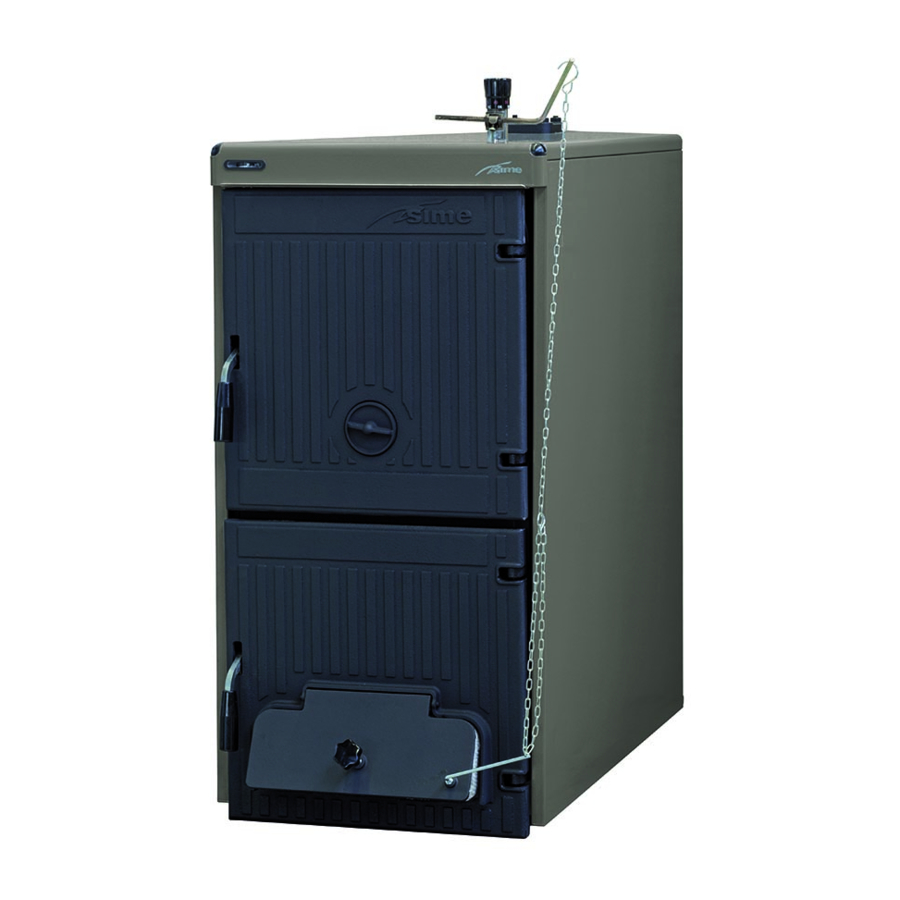
TECHNICAL AND DIMENSIONAL CHARACTERISTICS DESCRIPTION best. way. using. suitable. technologies. for. sure. maximum. thermal. yield. optimising. combustion. draught..The.boilers.are.in.compliance.with. Wood.is.an.alternative.source.of.energy.and. Iron.cast.and.traditional.combustion.wood. PED.Directive.2014/68/UE.and.Standard.EN. boilers. SOLIDA EV. are. designed. to. en- 303-5/2012. it. is. also. precious;. therefore,. use. it. in. the. OVERALL DIMENSIONS (fig. 2) M. - Page 5 3.3.1 Technical data with kit that can be switched from class 1 to class 3 (to be requested separately) SOLIDA EV Kit that can be switched from class 1 to class 3 8075990 8075991 8075992 8075993 8075994 Heat capacity with wood. 11,0.
-
Page 6: Installation
INSTALLATION BOILER ROOM resistant.to.temperature.of.smokes.and. CONNECTION OF THE PLANT related.condensations.. Check.that.the.room.has.the.requirements. –. It. should. be. of. a. sufficient. mechanical. The. connections. should. be. easily. discon- resistance.and.a.weak.thermal.conduc- and.features.in.accordance.to.the.rules.in. nected.by.means.of.pipelines.with.revolving. force.. Furthermore,. the. room. should. be. tivity. joints.. It. is. always. advisable. to. assemble. aired,. -
Page 7: Assembling The Accessories
tents). –. Frequent. replenishment. water. inlets. in. the.plant. –. If. the. partial. or. total. emptying. of. the. 1. Handle plant.should.be.necessary.. 2. Load.port 3. Roll 4. Elastic.split.pin ASSEMBLING THE ACCESSORIES (fig. 5 - fig. 5/a) Fig..5 The. port. closing. handles. and. the. screw. with.knob.for.the.air.gate.damper.regula- tion.is.supplied.separately,.as.they.can.be. - Page 8 wer.tie.rods,.both.in.the.front.and.rear.side. of. the. boiler,. two. nuts. are. tightened,. one. “THERMOMAT RT-C” Regulator of.which.is.used.to.block.the.side.support. brackets. The. assembly. of. the. casing. components. must.be.carried.out.in.the.following.way: –. Unscrew.with.some.rotations.the.second. or.third.nut.of.each.tie.rod. –. Connect.the.left.side.(1).on.the.lower.and. upper.tie.rod.of.the.boiler.and.adjust.the. position. of. the. nut. and. lock-nut. of. the. upper.tie-rod. –. Block.the.side.by.tightening.the.locknuts. –. In. order. to. assembly. the. right. side. (2). proceed.in.the.same.way.
-
Page 9: Hydraulic Connection Diagrams
HYDRAULIC CONNECTION DIAGRAMS 4.8.1 Open expansion tank system (fig. 9) . V E. Open.expansion.tank .VS. System.safety.valve.3.BAR.-.1/2” . V M.. Mixing.valve . V R.. Check.valve .PI.. System.pump .IR.. Heating.system Fig..9 4.8.2 Closed expansion tank system and safety exchanger with thermostatic valve (fig. 10) . -
Page 10: Use And Maintenance
USE AND MAINTENANCE PRELIMINARY CHECKS ter.(pos..1). get burned. BEFORE COMMISSIONING AIR ADJUSTMENT (fig. 11) CLEANING (fig. 12) Before. commissioning. the. boiler,. comply. with.the.following.instructions: –. The. system. connected. to. the. boiler. The. primary. air. is. adjusted. automatically. Cleaning. operations. must. be. carried. out. by. -
Page 11: Disposal Of The Equipment
If the safety valve should malfunction and cannot be re-calibrated, replace it with a new 1/2” valve calibrated to 3 BAR and conforming with Directive PED 2014/68/ DISPOSAL OF THE EQUIPMENT Once. it. reaches. the. end. of. its. operating. life,.the.equipment.MUST.BE.RECYCLED. in.line.with.current.legislation.
Need help?
Do you have a question about the SOLIDA EV 3 and is the answer not in the manual?
Questions and answers