Advertisement
Quick Links
INSTALLER INSTRUCTIONS
CONTENTS
1
DESCRIPTION OF THE BOILER . . . . . . . . . . . . . . . . . . . . . . . . . . . . . . . . . . . . . . . . . . . . . . . . . . . . . . . . . . . . . . . . . pag. 48
2
INSTALLATION . . . . . . . . . . . . . . . . . . . . . . . . . . . . . . . . . . . . . . . . . . . . . . . . . . . . . . . . . . . . . . . . . . . . . . . . . . . . . . . pag. 49
3
CHARACTERISTICS . . . . . . . . . . . . . . . . . . . . . . . . . . . . . . . . . . . . . . . . . . . . . . . . . . . . . . . . . . . . . . . . . . . . . . . . . . . pag. 53
4
USE AND MAINTENANCE . . . . . . . . . . . . . . . . . . . . . . . . . . . . . . . . . . . . . . . . . . . . . . . . . . . . . . . . . . . . . . . . . . . . . pag. 55
When carrying out commissioning of the boiler, you are highly recommended to perform the following checks:
- Make sure that there are no liquids or inflammable materials in the immediate vicinity of the boiler.
- Make sure that the electrical connections have been made correctly and that the earth wire is connected to a
good earthing system.
- Open the gas tap and check the soundness of the connections, including that of the burner.
- Make sure that the boiler is set for operation for the type of gas supplied.
- Check that the flue pipe for the outlet of the products of the combustion is unobstructed.
- Make sure that any shutoff valves are open.
- Make sure that the system is charged with water and is thoroughly vented.
- Purge the system, bleeding off the air present in the gas pipe by operating the pressure relief valve on the
gas valve inlet.
CHARACTERISTICS OF THE SYSTEM SAFETY VALVE: calibration pressure: 4 bar; maximum generator power: 205.8 Kw, 1/2"
x 3/4" fixtures (see Caleffi catalogue, code 527440).
FONDERIE SIME S.p.A of Via Garbo 7 -Legnago (VR)-Italy declares that its hot water boilers, which bear the EC mark
under Gas Directive 90/396/EEC and are fitted with a safety thermostat calibrated to a maximum of 110 °C, are
excluded from application of Directive PED 97/23/EEC in that they satisfy the requirements of article 1 paragraph
3.6 of this Directive.
IMPORTANT
Advertisement

Subscribe to Our Youtube Channel
Related Manuals for Sime 70 Mk.II


Summary of Contents for Sime 70 Mk.II
- Page 1 3/4” fixtures (see Caleffi catalogue, code 527440). FONDERIE SIME S.p.A of Via Garbo 7 -Legnago (VR)-Italy declares that its hot water boilers, which bear the EC mark under Gas Directive 90/396/EEC and are fitted with a safety thermostat calibrated to a maximum of 110 °C, are excluded from application of Directive PED 97/23/EEC in that they satisfy the requirements of article 1 paragraph 3.6 of this Directive.
-
Page 2: Description Of The Boiler
C.H. return ” M C.H. flow ” Gas connection 1” Boiler/filling drain 3/4” mm ø mm mm mm 70 Mk.II 645 415 80 Mk.II 645 415 90 Mk.II 1040 200 645 415 100 Mk.II 1140 225 645 415 110 Mk.II 1240 250 670 400 Fig. -
Page 3: Installation
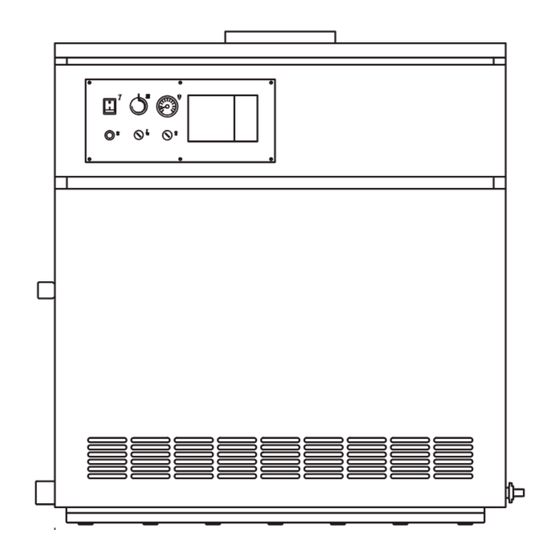
MAIN COMPONENTS Gas valve with coil assembly 1/2” bulb holder Safety stat Lock out reset button Main switch Regulation sta with double contact Thermometer Smoke stat (“70 - 80 - 90 100” models) 1/8” pressure test point (“110” models) 1/8” pressure test point Burner manifold Fig. - Page 4 gas main pipes. To prevent malfunctioning of the valve, or in certain cases even to cut out the safety device with which the valve is equipped, install an adequate filter on the gas pipe. SYSTEM FILLING Filling must be done slowly so as to allow any air bubbles to be bled off through the air vents provided on the heating system.
- Page 5 The boiler is supplied with an electric cable. Tetto a 30 ° 30° roof Should this require replacement, it must be purchased exclusively from SIME. The elec- > 1,30 m Colmo tric power supply to the boiler must be ≤ 1,30 m...
- Page 6 2.6.2 Wiring diagram “RMG 70-80-90-100 Mk.II” models CONNECTOR SPARE PART CODES: J1 code 6278669 J2 code 6278670 “RMG 110 Mk.II” models CONNECTOR SPARE PART CODES: J1 code 6293511 J3 code 6293512 J4 code 6293510 Control box Fuse (T 200mA) Main switch Smoke stat Isolated transformer Regulation stat with...
-
Page 7: Characteristics
CONTROL SYSTEM RVA43.222 (optional) All the boiler functions can be operated by optional control system code 8096303, supplied with external tempera- ture sensor (SE), boiler immersion sensor °C (SC) (fig. 7). Another series of low tension 1 Plastic hole cover connectors may be connected to the con- 2 Control system trol system, these are used for the con-... - Page 8 3. 1 . 1 Operating cycle When there is a sudden voltage failure, the lowing advantages: burner shuts out immediately; when power – higher overall boiler efficiency; Before igniting the boiler, use a voltmeter to supply returns, the boiler will start up again –...
-
Page 9: Use And Maintenance
“VR 4605 C - VR 4605 CB” EV1 coil Pressure regulator Calibration of the operating pressures is Coil assembly done by SIME in the factory. Consequently EV2 coil they should not be altered. Only when you LPG adaptor switch to another type of gas (butane or... - Page 10 SIME in the factory. Consequently they should not be altered. Only when you switch to another type of gas (butane or propane) is it permitted to alter the opera- ting pressures. It is essential that this operation be car- ried out exclusively by authorized techni- cal staff.
- Page 11 on terminals 6 and 7 of the boiler termi- nal board). Boiler operates only at nominal pressure and does not reduce pressure. – Check whether there is voltage at both ends of coil. Boiler body – The coil has a break in the winding; replace. Burner –...
- Page 12 USER INSTRUCTIONS WARNINGS – In case of fault and/or incorrect equipment operation, deactivate it, without making any repairs or taking any direct action. Contact the nearest Authorised Technical Service Centre. – The installation of the boiler and any servicing or maintenance job must be carried out by qualified personnel. Under no circumstances, the devices sealed by the manufacturer can be tampered with.
- Page 13 LOCK OUT RESET OF THE CONTROL BOX If the burner does not ignite, the red led on the reset button will turn on. Press the but- °C ton to restart the boiler automatically (fig. 18). Should the boiler “lock out” again, you must call the authorized technical staff.
- Page 14 CONTROL SYSTEM In order to get the highest potential out of the “RVA 43.222” regulator follow the instructions given below: TO TURN ON THE HEATING IF THE ROOMS ARE TOO HOT OR TOO COLD – Turn on the main switch. –...
- Page 15 *Caldaie a basse emissioni inquinanti (“classe 5” rispetto alle norme europee UNI EN 297 e EN 483). Legnago, 05 marzo 2009 Il Direttore Generale ing. Aldo Gava Fonderie Sime S.p.A. - Via Garbo, 27 - 37045 Legnago (Vr) - Tel. 0442 631111 - Fax Servizio Tecnico 0442 631292 - www.sime.it...
- Page 16 RX 55 CE 60,7 69,2 87,7 - 85,8 93,57 RX 26 BF 31,0 34,0 91, 1 - 91, 1 92,98 RMG 70 Mk.II 70, 1 77,9 90, 1 - 87, 1 93,69 RMG 80 Mk.II 78,7 87,4 90,0 -87,2 93,79 RMG 90 Mk.II...
- Page 17 DI CONTROLLO E DI REGOLAZIONE DIRETTIVA 90/396/CEE Si certifica che i dispositivi di sicurezza, di controllo e di regolazione impiegati sulle caldaie con bruciatore a gas ad aria aspirata marca SIME modello: RMG 70 Mk.II (portata termica 77,9 kW) RMG 80 Mk.II (portata termica 87,4 kW) RMG 90 Mk.II (portata termica 100,0 kW)
- Page 18 Fonderie Sime S.p.A - Via Garbo, 27 - 37045 Legnago (Vr) Tel. + 39 0442 631111 - Fax +39 0442 631292 - www.sime.it...
Need help?
Do you have a question about the 70 Mk.II and is the answer not in the manual?
Questions and answers