
Related Manuals for Ulvac VS Series


Summary of Contents for Ulvac VS Series
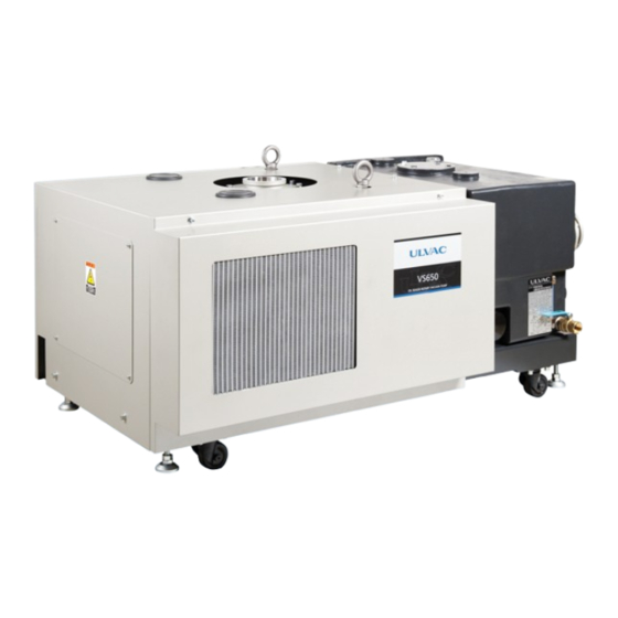
- Page 1 YK19-0009-DI-004-02 Oil Rotary Vacuum Pump INSTRUCTION MANUAL MODEL VS Series VS650B(-A, -W, -WL), VS750B(-A, -W)
-
Page 3: Before Using The Unit
Before Using the Unit Oil Rotary Vacuum Pumps from ULVAC, Inc. (hereinafter referred to as "our company"): VS650B (-A, -W, -WL), VS750B (-A, -W) (hereinafter referred to as "this unit") Thank you for purchasing this product. Upon receipt of the unit, please confirm the contents included are the same as you ordered and check the unit for any damage attributed to transportation etc. -
Page 4: About Safety Notation
About Safety Notation In this manual and warning signs on the unit, signal words and symbol marks are displayed in order for you to understand the matters to adhere. The meanings are shown below: ▶ Meaning of signal words: The terms that signify the warning level for safety are referred to as "Signal Words." This indicates an imminently hazardous situation which, if the unit is misused, will result in operator's death or serious injury. -
Page 5: Types And Display Position On Warning Labels
When this unit is stored without operation for a long period of time, problems with operation may occur due to the occurrence of rust or for other reasons. If the unit has not been used for a long period of time, contact your nearest ULVAC TECHNO or ULVAC service center for inspection. -
Page 6: Warning Label Display Position
▶ Warning Label display position ■ For VS650B-A, VS750B-A (Air cooling type) ■ For VS650B-W, VS650B-WL, VS750B-W (Water cooling type) Figure 1: Warning label pasting position YK19-0009-DI-004-02... -
Page 7: Warranty Clause
Warranty Clause This product is shipped after strict internal inspection. If you find any manufacturing defects, accidents during the transportation, or other defects attributed to our responsibility, please contact our Components Division at headquarters or the nearest sales office or agency. The repair/replacement is free of charge. ▶... -
Page 8: Disclaimer
▶ How to Respond (a) Domestic: An alternative is delivered or the product is sent back to us or the nearest our ULVAC TECHNO, Ltd. for repair. If it is necessary to respond on site, contact our Components Division, or the nearest sales office or agency for assistance. -
Page 9: Others(Warranty Clause
This manual is designed for a Japanese speaking user. When allowing a non-Japanese speaking user to work on the unit, provide a thorough safety education and handling instruction under the responsibility of the customer. This instructions manual is copyrighted by ULVAC's Components Division. YK19-0009-DI-004-02... -
Page 10: Applicable Model
Applicable Model This manual applies to VS650B (-A, -W, -WL), VS750B (-A, -W). The meaning of the symbols and numbers described in Model is as follows. Table 1: Model List *1: 600 m /h (50/60 Hz) for the low-noise L type. *2: VS750B is for 50 Hz only. -
Page 11: Table Of Contents
Table of Contents Before Using the Unit ......................i About Safety Notation ............................ii ▶ Meaning of signal words: ......................... ii ▶ Meaning of symbol marks: ........................ii Types and display position on warning labels ....................iii ▶ Types and explanation on warning labels ....................iii ▶... - Page 12 1.7.3 Electric Shock ............................8 1.7.4 High Temperature ........................... 9 1.7.5 Burst ............................... 9 1.7.6 Leakage of high-temperature cooling water ..................10 1.8 Safety Data Sheet ............................10 Product Overview ..................11 2.1 Features ..............................11 2.2 Application Purpose ........................... 11 2.3 Evacuation Principles ..........................
- Page 13 3.6.3 Cooling Water Piping (for Water Cooling Type) ................... 34 3.6.4 Gas Ballast Gas ............................ 36 3.6.5 Purge Gas ............................. 37 3.7 Electric Wiring ............................38 3.7.1 Wire Connection of Main Power Supply ....................40 3.7.2 Connection to Thermostat ........................46 3.7.3 Connection to Electromagnetic-Valve Type Gas Ballast Valve ............
- Page 14 6.2.12 Cleaning of Oil Pan..........................82 6.2.13 Maintenance/Cleaning of Heat Exchanger (for water-cooling type) ..........82 6.3 Inspection after Long-Term Storage ......................83 6.4 Overhaul..............................83 Troubleshooting .................... 84 7.1 Trouble with Basic Operation ........................84 Specifications ....................91 8.1 Performance Specifications ........................91 8.2 External Dimensions ..........................
-
Page 15: For Safe Use
Signifies, by each work, the method for avoiding danger and the actions prohibited to do for dangerousness reasons. 1.1 Handling the Unit Overhaul or repair service of this unit is offered by your nearest ULVAC TECHNO or ULVAC service center. Connect the power line of this unit to the EMO system of the host device. -
Page 16: Acceptance/Transfer/Storage
Contact a nearby sales office or agent. [Sales offices list] https://www.ulvac.co.jp/support_info/sales_office/ 1.2 Acceptance/Transfer/Storage 1.2.1 Acceptance Use appropriate protective equipment and dismantling tools when dismantling. -
Page 17: Transfer
An unqualified person shall neither perform a cargo-work nor operate a cargo-handling unit An unqualified person shall neither perform a cargo-work nor operate a cargo-handling unit. Ignorance to this may cause an accident or injury. Do not tilt this unit 10 degrees or more. Falling or other accidents may cause injury or damage. -
Page 18: Installation/Operation
Protect environmental conditions. This unit is a unit with precise clearances. Make sure that the storage location meets the "environmental conditions for storage." * For the environmental conditions, refer to "3.1.2 Environmental Conditions during Storage" on page 18. 1.3 Installation/Operation Do not remove the exterior panel. -
Page 19: Removal/Transport
Protect environmental conditions. This unit is a unit with precise clearances. Make sure that the storage location meets the "environmental conditions during installation and operation." * For the environmental conditions, refer to "3.1.3 Environmental Conditions during Installation and Operation" on page 19. Use the unit with a specified amount of oil. -
Page 20: Transportation
Fully seal the inlet/outlet port with a blind flange or cap, or by other means. After removing the inlet/outlet piping, fully seal the inlet/outlet port of this unit with a blind flange or cap, or by other means. 1.4.2 Transportation Do not use casters as a mobile means or a supporting means for this unit. -
Page 21: Protection Device
1.6 Protection Device Installation of an overload protection device is made mandatory by the Technical Standards for Electrical Installations. It is recommended to install a protective device (such as a ground-fault interrupter) other than the overload protection device. For selection of an overload protection device and a ground-fault interrupter, refer to "Table 9: Standard motor and wiring"... -
Page 22: Transfer Of Heavy Object
1.7.2 Transfer of Heavy Object Never get under this unit. The unit may drop or fall when hoisted if it is forcibly operated or the equipment is not properly maintained. Never get under this unit. An unqualified person shall neither perform a cargo-work nor operate a cargo-handling unit An unqualified person shall neither perform a cargo-work nor operate a cargo-handling unit. -
Page 23: High Temperature
1.7.4 High Temperature During operation or for a while after operation stops, do not touch the main unit, motor, or piping. During operation or for a while after operation stops, do not touch the main unit, motor, or piping as they are at a very high temperature. Otherwise, you may get burned. Install the protection cover to the piping. -
Page 24: Leakage Of High-Temperature Cooling Water
1.7.6 Leakage of high-temperature cooling water If this unit is operated without water supply, stop and keep it off. If this unit is operated without water supply, stop and keep it off. There is the risk that boiling high-temperature steam blows out from the inlet/outlet of cooling water. Provide an interlock in the cooling water system Install a flow meter in the cooling water system as an interlock so that this unit stops when the cooling water stops. -
Page 25: Product Overview
2. Product Overview The maximum evacuation rate of the oil rotary vacuum pump is 650 m /h at 50 Hz or 750 m /h at 60 Hz for "VS650B-A/VS650B-W," 600 m /h at both 50 Hz and 60 Hz for "VS650B-WL," or 750 m /h at 50 Hz for "VS750B-A/VS750B-W."... -
Page 26: Evacuation Principles
2.3 Evacuation Principles For VS650B and VS750B, three vanes are attached to a rotor installed inside the cylinder, and these vanes divide the inside of the cylinder into three spaces. Gas in the divided spaces is compressed with the rotation of the rotor, changes periodically, and is discharged to the atmosphere through the exhaust valve. -
Page 27: Required Power
2.4.3 Required Power The power for driving a vacuum pump is the sum of the work (mechanical work) against the rotational friction of mechanical elements and the work (compression work) that compresses the air, providing the maximum suction pressure between 2 × 10 and 4 ×... -
Page 28: Name And Function Of Parts
2.6 Name and Function of Parts Figure 4: Name of parts (VS650B/VS750B) Table 2: Name of Parts (VS650B/VS750B) Name Function Reference Connect the container and piping for evacuation. (DN100 ISO- Inlet port 3.6.1 Eyebolt Used when hoisting this unit using a crane. 3.3.1 Manual gas ballast Used when supplying gas ballast gas. - Page 29 Name Function Reference Adjuster foot Adjust the height of this unit. Caster These are swivel wheels. Air outlet (for air Draw in air to cool oil. cooling type only) 24 VDC power 3.7.2 The thermostat wire is connected to the terminal block. connection part (inside) 3.7.3 Wire exit port...
-
Page 30: System Configuration
2.7 System Configuration Perform the direct-connect starting of the pump. See Table 5 for required power capacity. ■ For VS650B-A, VS750B-A (Air cooling type) The power supply is the only required utility. Cooling water is unnecessary. ■ For VS650B-W, VS650B-WL, VS750B-W (Air cooling type) The cooling water and power supply are required as utilities. -
Page 31: Installation
3. Installation 3.1 Before Installation 3.1.1 Responsibility for Work from Shipping to Startup This unit is based on the premise that our company is responsible for packing to shipping (transportation) and the customer for receipt to startup. However, depending on the contract conditions of this unit, the customer may conduct all or part of transportation, unpacking, and installation. -
Page 32: Environmental Conditions During Storage
3.1.2 Environmental Conditions during Storage Do not store this unit with water sucked in. Do not store this unit with water sucked in. The inside of this unit may rust, resulting in a malfunction. If this unit is stored in a warehouse or front chamber before installation, or not used for a long period of time, store it following the conditions below. -
Page 33: Environmental Conditions During Installation And Operation
3.1.3 Environmental Conditions during Installation and Operation This unit is a unit with precise clearances. Satisfy the following during installation and operation. Ambient 10 to 40°C (for ULVOIL R-72) temperature Ambient humidity 80 %RH or less (No condensation allowed) Altitude 1,000 m or less of altitude above sea level No corrosive and explosive gases allowed. -
Page 34: Unpacking
3.2 Unpacking This unit is protected by stretch film, cushioning materials, or by other means, packed in a wooden frame or cardboard, and shipped. For packing in a crate, ask a specialist to dismantle it. Give the following precautions and instructions to the dismantling contractor. 3.2.1 Precautions for Unpacking Use appropriate protective equipment and dismantling tools when dismantling. -
Page 35: Check After Unpacking
3.2.2 Check after Unpacking After unpacking, check that the content is the same as what you ordered and that it is not damaged due to transportation. If you let us know after using the product, it may be borne by your company. Although the product has been shipped with extreme care, check the following points after unpacking just in case. -
Page 36: Transportation
3.3 Transportation Do not use casters as a mobile means or a supporting means for this unit. Do not use casters as a mobile means or a supporting means for this unit. Otherwise it may cause a malfunction. Use the casters for adjusting the position. Transfer this unit using cargo-handling equipment or a pallet truck. - Page 37 1. If this unit is packed with metal brackets, remove the metal brackets. 2. Prepare appropriate hoisting attachments and check the eyebolts for any abnormalities, such as looseness or damage. 3. Hook the hoisting attachments on the eyebolts of this unit and hook them on the hook of the crane. Figure 6: Hoisting using Crane 4.
-
Page 38: How To Transport Using Pallet Truck
3.3.2 How to Transport using Pallet Truck Do not transport this unit with the adjusters raised. When transporting using a pallet truck, lower the adjusters (4 places). Transportation of this unit with no adjusters on the pallet may cause this unit to tip over, resulting in injury or damage. 1. -
Page 39: Installation
3.4 Installation Arrange this unit in consideration of work, such as installation, removal, inspection, and cleaning, and release of exhaust gas to the outside. Install this unit in a horizontal position and fix it using vibration-proof rubbers to prevent looseness. Before installation or removal work, disconnect this unit from all energy sources. -
Page 40: Earthquake-Proof Measures
After transporting this unit to the installation site, adjust the adjusters so that it is installed as horizontally as possible (the adjustable range: +10 mm or less). If necessary, adjust the adjusters while checking the level. After adjusting the adjusters, fix it with hexagon nuts. Figure 9: Adjusters in Installation 3.4.2 Earthquake-Proof Measures Do earthquake-proof fixing. -
Page 41: Oil Filling
3.5 Oil Filling 3.5.1 Oil Filling Use the oil specified by our company. The standard oil "ULVOIL R-72" is available. Add oil so that the oil level is at the level line "MAX." of the oil level gauge. The pump can operate when the oil level is between the level lines of the oil level gauge during operation. - Page 42 Use the unit with a specified amount of oil. Be sure to use the unit with a specified amount of oil. If it exceeds the upper limit, oil may blow out from the outlet port when entering the atmosphere. In addition, if the oil level becomes lower than the lower limit during the operation, the bearings, shaft seals, etc.
- Page 43 Figure 11: Specified oil level YK19-0009-DI-004-02...
-
Page 44: Piping
When connecting the pipes, take care not to drop foreign matter (e.g. bolts) into the inlet/outlet port of this unit. If foreign matter drops, it is necessary to disassemble this unit and remove it. Contact your nearest ULVAC TECHNO or ULVAC service center. Do not apply loads directly to the inlet/outlet port of this unit. - Page 45 Install the protection cover to the piping. The temperature of the inlet/outlet piping is 70°C or more. After connecting the inlet/outlet port piping, install the protection cover. ■ Applicable Specifications Refer to "8.2 External Dimensions" on page 92. ■ Applicable Piping Piping according to the safety rules and laws and regulations in the country of destination.
-
Page 46: Inlet Port Piping
3.6.1 Inlet Port Piping Use the included inlet port only. The inside of the inlet port acts as the sealing surface of the check valve in structure. Use the included inlet port only. When connecting the pipe, remove the protective cap. A protective cap is attached to the inlet port at the factory. -
Page 47: Outlet Port Piping
3.6.2 Outlet Port Piping Do not block the outlet port. Do not operate the pump with any equipment installed on the outlet port side that prevents gas from passing in such a way as to block the outlet port. Pressure in this unit may increase, which causes a rupture of or oil leakage from the casing or level gauge, or overloads the electric motor. -
Page 48: Cooling Water Piping (For Water Cooling Type)
3.6.3 Cooling Water Piping (for Water Cooling Type) Use the piping with an appropriate resistant water pressure and heatproof temperature. For the cooling water system, use joints and pipes with a resistant water pressure of 0.5 MPaG or more and a heatproof temperature of 90°C or more. * When operating at the maximum load and the cooling water inlet temperature is 30°C, the cooling water outlet temperature becomes 90°C. - Page 49 Use water with fewer impurities for cooling water. It is recommended to use water with fewer impurities (e.g. industrial water; refer to the table below) for cooling water of this unit. In the cooling water system of this unit, water scale, such as calcium carbonate, settles on depending on the water quality, which may reduce the cooling water flow rate.
-
Page 50: Gas Ballast Gas
■ Specifications of connection Connection port: G1/2 ■ Applicable piping Joints and pipes with a resistant water pressure of 0.5 MPa or more Heatproof temperature: 90°C or more Table 6: Specifications of cooling water Supply pressure (MPa) 0.5 or less Differential pressure between inlet and outlet 0.1 or more Cooling water... -
Page 51: Purge Gas
Figure 13: Manual gas ballast valve position * For the gas ballast function, refer to "4.4 Gas Ballast Function" on page 59. 3.6.5 Purge Gas This unit has a purge gas port. By introducing purge gas, most of the air built up in the oil tank can be expelled. Remove the seal plug and introduce CDA (dew point: -60°C) or nitrogen as a purge gas. -
Page 52: Electric Wiring
3.7 Electric Wiring Use cables certified by the national safety standards. Use cables certified by the national safety standards in the country of destination (e.g. products certified by UL, TUV). Comply with Rules and Laws and Regulations. Install and operate this unit in compliance with the safety codes and laws (e.g. fire protection laws and electric codes) in the country and region where you use this unit. - Page 53 Provide a ground-fault interrupter. In the event of a short circuit, it protects the equipment and wiring and protects against overload. In addition, it protects against an electric shock and a ground fault that can lead to fire due to electric leakage. If no ground-fault interrupter is installed or if it is installed but does not match the motor capacity, it causes damage to equipment, fire, or an electric shock.
-
Page 54: Wire Connection Of Main Power Supply
Example: STO (Size: AWG4 / No. of cores: 4) - Outer diameter of core: approx. φ10 / Allowable current value: approx. 110 A (ambient temperature: 30°C) 2PNCT (Size: 22 mm2 / No. of cores: 4) - Outer diameter of core: approx. φ9 / Allowable current: approx. - Page 55 Install grounding wires so that the wire lengths become as short as possible. The ground terminal on the motor side is the screw indicated by the ground mark in the terminal box. The power cord size connected to the ground must be at least the same as that of the power cord for the power supply to the motor.
- Page 56 Screw for ground terminal Screw for terminal box Wire outlet Figure 16: Major dimensions of terminal box YK19-0009-DI-004-02...
- Page 57 Table 8: Terminal block connection confirmation and wiring layout change method Sequence Procedure Picture No.1 Open the cover of the terminal box and check which connection is used for the connection of the terminal block, YY connection, Y connection, or Δ connection. Check the power supply voltage to be used.
- Page 58 How to change the layout of wiring Sequence Procedure Picture No.2 To facilitate rearrangement, remove all nuts and all shorting plates from the terminal block while holding the terminals in place. No.3 The terminals (a and b) in the center of the terminal block must be replaced.
- Page 59 Table 9: Standard motor and wiring YK19-0009-DI-004-02...
-
Page 60: Connection To Thermostat
3.7.2 Connection to Thermostat A thermostat is provided as standard on this unit to protect the pump when the pump overheats abnormally and exceeds the set temperature (115°C). However, if necessary, install wiring to the 24-VDC power supply connection so that the power supply is shut off when the thermostat is activated. This thermostat is a bimetal type which opens the contact with an increase in temperature to cut off continuity. -
Page 61: Connection To Electromagnetic-Valve Type Gas Ballast Valve
3.7.3 Connection to Electromagnetic-Valve Type Gas Ballast Valve When you have ordered an optional solenoid valve type gas ballast valve, it can be opened/closed remotely by wiring a single-phase 24 VDC to the 24-VDC power connection part of "Figure 20: Connection wiring diagram of 24-VDC power wire connection (Electromagnetic-valve type gas ballast valve)"... -
Page 62: Starting With Inverter
3.7.4 Starting with Inverter If the power capacity required for the direct-connect starting at 200 VAC/60 Hz cannot be prepared, start with an inverter (sold separately). Please use the "YY connection" for the motor connection. The recommended inverter is CIMR-AA2A0081 (Three-phase 200V, light-load rating ND, maximum applicable motor: 22 kW) of A1000 Series manufactured by YASKAWA Electric Corporation. -
Page 63: Operation
4. Operation 4.1 Cautions on operation Do not suck any gas other than inert gas. This unit is to exhaust inert gas (air, nitrogen, argon). If other gases (toxic gas, combustion gas, combustion-supporting gas, corrosive gas, explosive gas) are exhausted, they leak from the main unit of this unit or the parts of this unit are corroded and damaged. - Page 64 If it does not work or there is an abnormality, immediately turn off the power switch. If it does not work or there is an abnormality, immediately turn off the power switch to prevent accidents. Contact your nearest ULVAC TECHNO or ULVAC service center for inspection/repair. Do not block the outlet port.
- Page 65 Do not put your fingers or objects in the opening of the motor. Do not put your fingers or objects in the opening of the motor. There is a risk of electric shock, injury, fire, or other problems. Do not touch rotating parts, such as the motor, spindle, and shaft joints, during operation.
- Page 66 Be sure to supply the specified amount of cooling water. If the amount of cooling water is reduced, it may cause failures such as rapid wear or seizing up of the components of this unit. Take care especially in high pressure regions as this is highly likely to occur there.
- Page 67 For continuous operation at high suction pressures, change oil frequently. Continuous operation at high suction pressures causes an extremely high oil temperature. Consequently, the oil rapidly deteriorates, resulting in poor ultimate pressure and displacement, rapid wear of the parts, or failures such as seizing up. Change oil frequently. It is also effective to install an oil cooler to cool the oil inside the pump.
-
Page 68: Preparation For Operation
4.2 Preparation for Operation Do not block the outlet port. Do not operate the pump with any equipment installed on the outlet port side that prevents gas from passing in such a way as to block the outlet port. Pressure in this unit may increase, which causes a rupture of or oil leakage from the casing or level gauge, or overloads the electric motor. - Page 69 ■ How to confirm the direction of the motor rotation Make the checks with the vacuum valve closed and the leak valve open. The vacuum gauge is prevented from being damaged or jumped out in the reverse rotation. 1) Operate this unit for approx. 1 to 2 seconds and stop it. 2) During the above operation, check the direction of motor rotation viewed from the motor connection part.
-
Page 70: Startup And Stop Operation Method
4.3 Startup and stop operation method 4.3.1 Startup Warm up for approx. 30 minutes (recommended) after startup. In order to make full use of the exhaust performance of this unit, it is recommended to warm up for approx. 30 minutes after startup. To start this unit, follow the procedure below. -
Page 71: Stop
4.3.2 Stop The inlet port of this unit has a function to seal the inlet port when this unit stops. This keeps the inside of the vacuum vessel in a vacuum even after the unit stops. During operation or for a while after operation stops, do not touch the main unit, motor, or piping. -
Page 72: Drain Of This Unit
4.3.3 Drain of this unit Perform drain work when there is a risk of freezing or when this unit is not used for a long period of time. Drain water in this unit. Drain water in this unit. Accumulated water may cause a failure, such as rusting inside this unit and damage to the parts due to freezing ■... -
Page 73: Gas Ballast Function
4.4 Gas Ballast Function This unit comes equipped with the gas ballast function as standard. If the target gas contains a condensable gas and moisture, use the gas ballast gas to prevent liquid from accumulating inside the main unit. When air or nitrogen is introduced from the gas ballast valve immediately before the compression process of the pump, the condensable gas is discharged together through the exhaust valve without being liquefied. - Page 74 ■ Operating procedure of gas ballast function Close the gas ballast valve before starting operation. Be sure to close the gas ballast valve before starting operation. In high pressure regions, oil may blow out from the gas ballast valve. Do not introduce compressed air into the gas ballast port. Do not introduce compressed air (CDA with a dew point of -60℃...
-
Page 75: Removal
5. Removal Before installation or removal work, disconnect this unit from all energy sources. Before installation or removal work, disconnect this unit from all energy sources (such as electricity, compressed air, and cooling water). * If you are using compressed air, nitrogen gas, or other gases, remove it. Wait for the temperature of the main unit to decrease. -
Page 76: Removal Of Piping
5.1 Removal of Piping 5.1.1 Cooling Water Piping (for Water Cooling Type) Wait for the temperature of the main unit to decrease. Immediately after operation is stopped, the main unit is at a high temperature. Wait for a while until the temperature of the main unit decreases and then remove and check the parts. Otherwise, you may get burned. -
Page 77: Inlet/Outlet Port Piping
5.1.2 Inlet/Outlet Port Piping Remove according to the installation manual for the equipment on the primary side. Remove according to the installation manual for the equipment on the primary side. After the temperature of the main unit decreases, remove the piping for the inlet/outlet port. -
Page 78: Maintenance/Inspection
6. Maintenance/Inspection Daily and regular inspection and maintenance work are required to maintain the original performance of this unit and ensure safe use. Before inspection/relocation, turn off the primary power. Before inspection/relocation, be sure to turn off the primary power. There is the risk of electric shock. -
Page 79: Regular Check
Item Check item Troubleshooting Is there any deposition of water or Wipe off water/oil. oil? Check water and oil for leakage. Check the inlet-side pressure and Current/Voltage value Is the pump loaded? exhaust piping. The oil level gauge attached to this unit is for checking the amount of oil. There is a little circulation with oil inside the pump case and, even after the long-time operation, the oil inside the oil level gauge may be less contaminated or discolored. - Page 80 If the desired ultimate pressure is not obtained even after changing the oil, an overhaul is necessary. Contact your nearest ULVAC TECHNO or ULVAC service center. Table 10: Guideline for oil change interval...
-
Page 81: Oil Leakage Check
When using the gas ballast function, the air filter element may be clogged with dust or the like. Check that there is no clogging. If it seems to be clogged, contact your nearest ULVAC TECHNO or ULVAC service center. Inspection of air filter element Stop the pump. - Page 82 Install the three nuts and then the panel in reverse order. YK19-0009-DI-004-02...
-
Page 83: Checking Abnormal Noise/Vibration
6.2.4 Checking Abnormal Noise/Vibration If any abnormal noise or vibration occurs in the pump, check the following. If the trouble persists even after checking these items, contact the nearest service center. Description Troubleshooting Is there any looseness in the nuts and Provide additional tightening. -
Page 84: Belt Tension Check/Re-Tightening/Replacement
6.2.5 Belt Tension Check/Re-Tightening/Replacement The belt connecting between the pump body and the motor is made of rubber. Continuous operation with insufficient tension wears the belt wear in a short time. ■ Initial break-in In early stages of operation, the belt tension is loosened due to the elongation of the belt itself and the fit with the pulley (the belt falling into the groove of the pulley). - Page 85 ■ Re-tightening of belt Stop the pump. Remove the front panel, back panel, and top panel in order. Loosen the four nuts (nuts indicated by the arrows) that fix the motor. Fully loosen the two bolts (indicated by the arrows) for the motor base on the pump side. Leave a space of 60 mm or more between the seating faces.
- Page 86 Check that the belt tension is within the specified values and that the pulleys are parallel. If not, make adjustments again in Step 5. Tighten the two bolts (indicated by the arrows) for the motor base on the pump side to a torque of 50 Nm.
- Page 87 ■ Replacement of belt Stop the pump. Remove the front panel, back panel, and top panel in order. Loosen the four nuts (nuts indicated by the arrows) that fix the motor. Fully loosen the two bolts (indicated by the arrows) for the motor base on the pump side. Leave a space of 60 mm or more between the seating faces.
- Page 88 When loosening the two bolts (indicated by the arrows) for the motor base on the side opposite to the pump, the motor moves in the direction where the belt is tightened. Gradually tighten the bolts in the order of front -> rear -> front -> rear -> ... Check that the belt tension is within the specified values and that the pulleys are parallel.
-
Page 89: Inspection/Replacement Of Oil Mist Separator
6.2.6 Inspection/Replacement of Oil Mist Separator This unit comes equipped with an oil mist separator as standard. The oil mist separator separates oil from the gas discharged from the pump. Severe clogging of the separator can prevent exhaust gas from passing through the filter, increasing the pressure inside the pump and causing the pump and oil mist separator to burst. - Page 90 Remove the four bolts on the side of the end plate with a handle of the oil mist separator. Remove the oil mist separator. Before installing a new oil mist separator, make sure that there are three washers in each hole. Install an O-ring to the outer regions of the opening of the new oil mist separator.
-
Page 91: Checking Check Valve
6.2.7 Checking Check Valve This unit comes equipped with a check valve at the inlet port as standard. The check valve has a function to prevent oil from flowing into the chamber and maintain the inside of the chamber in a vacuum when the pump is stopped. -
Page 92: Replacement Of Exhaust Valve Plate
6.2.8 Replacement of Exhaust Valve Plate Replace the exhaust valve plate every 8,000 hours. It may break early due to suction of foreign matter and water. ■ Replacement of Exhaust Valve Plate Stop the pump. Remove the front panel, back panel, and top panel in order. Remove the exhaust valve chamber cover. -
Page 93: Cleaning Of Oil Tank
6.2.9 Cleaning of Oil Tank The sucked foreign matter, products, sludge of pump oil, etc. are accumulated inside the oil tank. If the amount of deposit increases, it cannot be removed only by changing oil, which may cause damage to the pump as the contaminated/degraded pump oil is used for lubrication. -
Page 94: Checking Automatic Drain Valve
6.2.10 Checking Automatic Drain Valve If the ultimate pressure does not drop from several hundred Pa or so, it can be a fault in the automatic drain valve. Check the automatic drain valve. Stop the pump. Remove the oil tank cover circled below. Remove the four inner bolts circled. -
Page 95: Replacement Of Oil Filter
6.2.11 Replacement of Oil Filter This unit comes equipped with an oil filter as standard. The oil filter removes impurities contained in oil that circulates in the pump. If the amount of oil circulation is reduced due to a clogged oil filter, it may cause failures such as rapid wear or seizing up of the parts. -
Page 96: Cleaning Of Oil Pan
Regularly check the oil pan whether or not oil is accumulated. If oil is accumulated, wipe it off. If oil accumulates frequently, the oil seal may be deteriorated. Contact your nearest ULVAC service center for an overhaul. Stop the pump. -
Page 97: Inspection After Long-Term Storage
"Appendix: Major Replacement Parts." For overhauls, contact your nearest ULVAC TECHNO or ULVAC service center. Note that when making a request to overhaul, be sure to complete and submit the contamination certificate at the end of this document. If details on the dangerous substances in use is not disclosed or if difficult-to-detoxify substances are exhausted, ULVAC TECHNO or the ULVAC service center may refuse to perform maintenance or other operations. -
Page 98: Troubleshooting
- other safety circuits are faulty. circuits Contact your nearest ULVAC TECHNO End of Faulty motor or ULVAC service center. (Replace the Document motor.) Contact your nearest ULVAC TECHNO The pump Moisture, solvents, or other or ULVAC service center. (Cleaning... - Page 99 Or eliminate the cause of leakage. Contact your nearest ULVAC TECHNO End of The slow leak hole is clogged. or ULVAC service center. (Cleaning the Document slow leak hole in the oil tank) The phenomenon caused by the There is a "clattering" sound when temporary irregular movement of the -...
- Page 100 ULVAC TECHNO Document the level gauge. or ULVAC service center (Replacement of cylinders, rotors, vanes, and covers). Contact your nearest ULVAC TECHNO or ULVAC service center. (Removal of End of There is foreign matter in the pump. foreign matter, replacement...
- Page 101 Contact your nearest ULVAC TECHNO End of Our genuine oil is not used. or ULVAC service center. (After an Document overhaul, replace with our genuine oil.) Just after new oil has been added Operate at no load for a while.
- Page 102 The speed is incorrect (the power Contact your nearest ULVAC TECHNO frequency does match or ULVAC service center. (Replace with - applicable frequency of the motor motor pulleys of appropriate frequency.) pulleys). The foundation bolts (pump fixing Additionally tighten the bolts.
- Page 103 Problem Cause Measures Reference Contact your nearest ULVAC TECHNO Abnormal sliding of the rotors, End of or ULVAC service center. (Internal vanes. Document inspection/repair) Continuous operation at a high Pressure regulation - suction pressure. Cooling water does not flow. Supply cooling water.
- Page 104 In such a case, jog the pump (short-time ON-OFF operation) several times. *2: If the pressure does not drop even after the oil is changed, internal cleaning is required. Contact your nearest ULVAC TECHNO or ULVAC service center. YK19-0009-DI-004-02...
-
Page 105: Specifications
8. Specifications 8.1 Performance Specifications Model VS650B-A VS650B-W VS650B-WL VS750B-A VS750B-W Maximum Pumping Speed 50Hz 650(10833) 750(12500) 600(10,000) Can Not Use 60Hz 750(12500) /h(L/min) GP Closed ≦ 8 Ultimate Pressure GP1 Opened ≦ 70 GP2 Opened ≦ 200 Pa *1 Maximum 50Hz 4500 2500... -
Page 106: External Dimensions
8.2 External Dimensions Figure 23: Outline drawing (VS650B-A, VS750B-A) Figure 24: Outline drawing (VS650B-W, VS650B-WL, VS750B-W) YK19-0009-DI-004-02... -
Page 107: Appendix
Appendix Major replacement parts This shows the parts list for replacement through an overhaul: Bird's-eye view Required Parts name Specifications amount O-ring Shared O-ring Shared O-ring Shared O-ring (P8) Shared O-ring (P10) Shared O-ring Shared O-ring Shared O-ring (P7) Shared Valve seat Shared O-ring... - Page 108 This shows the parts list for replacement at intervals of 8,000 hours. Bird's-eye view Required Parts name Specifications amount Exhaust valve plate Shared Exhaust valve guide (shared) Shared Replace the parts shown below when it is deemed necessary to replace them due to scratches or clogging. Required Bird's-eye view No.
- Page 109 Base Unit Assembly Base Unit Assembly Position Parts Name Q'ty Material Dimensions Replace Base Assembly Caster Rubber Mount Motor Base 180M Hexagon Head Bolt SS400 M12x50 Plain Washer SS400 Spring Lock Washer SS400 Oil Tank Assembly Pump Assmbly Rubber Mount Spacer SS400 L=45...
- Page 110 Oil Tank Assembly Oil Tank Assembly (1/2) Position Parts Name Q'ty Material Dimensions Replace AC4A O-ring G240 O-ring G405 O-ring G335 Oil Tank Cover 1 Hexagon Head Bolt SS400 M12x20 Oil Tank Cover 2 Hexagon Head Bolt SS400 M12x20 Oil Tank Cover 3 Hexagon Head Bolt SS400 M12x20...
- Page 111 Oil Tank Assembly (2/2) Position Q'ty Parts Name Material Dimensions Replace Square Head Tapered Pipe Plug Fitting SUS304 for φ10-R1/4 Fitting SUS304 for φ16-R1/2 Oil Cooling IN Tube 1 SUS304 φ16xt1.0 Fitting SUS304 for φ16 Block SPHC t3.0 Seal Plug G1/4 O-ring Seal Plug...
- Page 112 Pump Assembly Pump Assembly Position Parts Name Q'ty Material Dimensions Replace Cylinder FC250 Parallel Pin S45C O-ring G300 O-ring G370 O-ring Hexagon Socket Headless Tapered Pipe Plug R1/4 Bush L=20 Bush L=30 O-ring Rotor-Shaft FCD450 O-ring Pulley Side Cover FC250 Hexagon Socket Headless Tapered Pipe Plug R1/4 Oil Seal...
- Page 113 Totally Enclosed External Fan Cooled Motor Type Assembly [ Standard ] Totally Enclosed External Fan Cooled Motor Type Assembly Position Q'ty Parts Name Material Dimensions Replace Totally Enclosed External Fan Cooled Motor Panel 4 (Soundproof material inside) SPHC t2.0 Cross Recessed Hexagon Head Screw with Captive Washer SS400 M5x8 Electrical Box...
- Page 114 Flame-Proof Motor Type Assembly [ External Option ] Flame-Proof Motor Type Assembly Position Q'ty Parts Name Material Dimensions Replace Flame-Proof Motor Panel 5 ( Soundproof material inside ) SPHC t2.0 Cross Recessed Hexagon Head Screw with Captive Washer SS400 M5x12 YK19-0009-DI-004-02...
- Page 115 Pumping Speed 650m /h Type Assembly [ Standard Select ] Pumping Speed 650m /h Type Assembly Position Q'ty Parts Name Material Dimensions Replace Pulley φ200-B-3 Hexagon Socket Set Screw SCM435 M10x16 S45C 14x9 Pulley Disk SPHC Hexagon Head Bolt SCM435 M24x50 Spring Lock Washer SS400...
- Page 116 Pumping Speed 750m /h Type Assembly [ Standard Select ] Pumping Speed 750m /h Type Assembly Position Q'ty Parts Name Material Dimensions Replace Pulley φ200-B-3 Hexagon Socket Set Screw SCM435 M10x16 S45C 14x9 Pulley Disk SPHC Hexagon Head Bolt SCM435 M24x50 Spring Lock Washer SS400...
- Page 117 Pumping Speed 600m /h Type Assembly [ Standard Select ] Pumping Speed 750m /h Type Assembly Position Q'ty Parts Name Material Dimensions Replace Drive Pulley (for 50Hz) φ192 Hexagon Socket Set Screw SCM435 M10x16 S45C 14x9 Pulley Disk SPHC Hexagon Head Bolt SCM435 M24x50 Spring Lock Washer...
- Page 118 Air Cooling Type Assembly [ Standard Select ] Air Cooling Type Assembly Position Q'ty Parts Name Material Dimensions Replace Panel 1 ( Soundproof material inside ) SPHC t2.0 Cross Recessed Hexagon Head Screw with Captive Washer SS400 M8x12 Panel 3 ( Soundproof material inside ) SPHC t2.0 Cross Recessed Hexagon Head Screw with Captive Washer...
- Page 119 Water Cooling Type Assembly [ Standard Select ] Water Cooling Type Assembly Position Q'ty Parts Name Material Dimensions Replace Panel 1 (Soundproof material inside) SPHC t2.0 Cross Recessed Hexagon Head Screw with Captive Washer SS400 M8x12 Panel 3 (Soundproof material inside) SPHC t2.0 Cross Recessed Hexagon Head Screw with Captive Washer...
- Page 120 With Oil Filter Assembly [ Standard ] With Oil Filter Type Assembly Position Q'ty Parts Name Material Dimensions Replace Oil Filter φ96x170 Double Union @:replace whenever overhauling ↑ . YK19-0009-DI-004-02...
- Page 121 Without Oil Filter Assembly [ External Option ] Without Oil Filter Type Assembly Position Q'ty Parts Name Material Dimensions Replace Oil Filter ByPass A1000 Double Union O-ring @:replace whenever overhauling ↑ . YK19-0009-DI-004-02...
- Page 122 Back Flow Prevention Valve With Spring Assembly [ Standard ] Back Flow Prevention Valve With Spring Assembly Position Q'ty Parts Name Material Dimensions Replace Back Flow Prevention Valve Spring SWPA OD19xID17 Hexagon Socket Headless Tapered Pipe Plug R1/4 (@): replace only seal parts↑ . YK19-0009-DI-004-02...
- Page 123 ISO Flange Type Assembly [ Standard ] ISO Flange Type Assembly Position Q'ty Parts Name Material Dimensions Replace Flange t6.0 Hexagon Head Bolt SS400 M10x20 O-ring V120 O-ring V175 Inlet Port DN VG150A-DN100ISO-K Hexagon Head Bolt SS400 M10x30 Plain Washer SS400 Spring Lock Washer SS400...
- Page 124 JIS Flange Type Assembly [ External Option ] JIS Flange Type Assembly Position Q'ty Parts Name Material Dimensions Replace Flange t6.0 Hexagon Head Bolt SS400 M10x20 O-ring V120 O-ring V175 Inlet Flange JIS VG150A-JIS100A Hexagon Socket Head Cap Screw SS400 M10x40 Outlet Flange JIS VG100A-JIS100A...
- Page 125 1 Gas Ballast Valve ( Manual ) Assembly [ Standard ] 1 Gas Ballast Valve (Manual) Assembly Position Q'ty Parts Name Material Dimensions Replace Fitting BRASS for φ15-R1/2 Street Elbow R1/2 3-Way 4Seats Ball Valve BRONZE R1/2 Check Valve Air Filter Element Rear Plate SPHC Front Plate...
- Page 126 1 Gas Ballast Valve ( Solenoid Valve ) Assembly [ External Option ] 1 Gas Ballast Valve (Solenoid Valve) Assembly Position Q'ty Parts Name Material Dimensions Replace Fitting BRASS for φ15-R1/2 Street Elbow R1/2 3-Way 4Seats Ball Valve BRONZE R1/2 Check Valve Air Filter Element Rear Plate...
- Page 127 This mark is applied to the electronic information product sold in the People's Republic of China. The figure at the center of the mark is the validity date of environmental protection. This product does not influence the environment, the human body and the property during the period reckoning the manufacturing date as long as the caution for safe use regarding the products are observed.
Need help?
Do you have a question about the VS Series and is the answer not in the manual?
Questions and answers