Table of Contents
Advertisement
Quick Links
Advertisement
Table of Contents

Subscribe to Our Youtube Channel
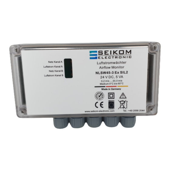
Summary of Contents for Seikom Electronic NLSW 45-3 SIL2
- Page 1 User Manual NLSW®45-3 SIL2 24 V AC/DC, 230 V AC Version 1...
- Page 2 +49 2058 2044 • info@seikom-electronic.com • www.seikom-electronic.com Page 2...
-
Page 3: Table Of Contents
User Manual NLSW®45-3 SIL2 TABLE OF CONTENTS TABLE OF CONTENTS ......................3 1. SAFETY INSTRUCTIONS ....................4 2. GENERAL INFORMATION ....................4 2.1 Areas of application and practical use ..................4 2.2 Operating principle ........................4 3. TECHNICAL DATA ......................5 3.1 Dimensions .......................... -
Page 4: Safety Instructions
User Manual NLSW®45-3 SIL2 1. SAFETY INSTRUCTIONS Please read the product description carefully before operating the unit. Make sure that the product is suitable for your application without any restrictions. Improper use or use not in accordance with the intended purpose can lead to malfunctions of the unit or undesirable effects on your application. -
Page 5: Technical Data
User Manual NLSW®45-3 SIL2 3. TECHNICAL DATA NLSW®45-3 SIL2 Article number 77029SIL2 63377SIL2 Operating voltage 24 V AC/DC 230 V AC 50/60 Hz Voltage tolerance ± 10% ± 5% Overvoltage category Signal lamp voltage Green LEDs Power consumption 5 VA 11 VA Ambient temperature unit -20°C …... -
Page 6: Dimensions
User Manual NLSW®45-3 SIL2 3.1 Dimensions 4. INSTALLATION AND COMMISSIONING Installation and commissioning must be carried out by authorised and qualified personnel. 4.1 Installation conditions of the airflow sensors The following installation conditions must be observed for the F3.x SIL2 sensor: ▪... -
Page 7: Installation
User Manual NLSW®45-3 SIL2 ▪ The sensors are independent of the installation position. ▪ The sensors must be connected to the airflow monitor according to the connection diagram. Mixing up the connections will lead to malfunctions and possible damage. ▪ If the sensor cable is laid in a duct together with other current-carrying cables (e.g. -
Page 8: Commissioning The Device
User Manual NLSW®45-3 SIL2 Sensor A Sensor B Sensor A Sensor B Relay A Relay B Output A Output B Colour code: GY = grey | BK = black | BN = brown 4.4 Commissioning the device The two potentiometers (purple) fixed with protective lacquer are factory-set and must not be adjusted. -
Page 9: Switching Point Adjustment
User Manual NLSW®45-3 SIL2 Connect PLC or control to relay output A and B via the supplied terminals (green). Please note the contact assignment NO/NC and switching. Potentiometer „Empfindlichkeit/Sensitivity“ (dark blue) set to left stop (insensitive) for both channels. Potentiometer "Anlaufüberbrückung/ start-up bypass“ (orange) to the desired start-up bridging time approx. -
Page 10: Troubleshooting
The following instructions are intended as first aid in case your airflow monitor does not work properly. If you have any further questions, the SEIKOM Electronic team will be happy to assist you by telephone or e-mail at any time. -
Page 11: Eu Declaration Of Conformity
User Manual NLSW®45-3 SIL2 6. EU DECLARATION OF CONFORMITY +49 2058 2044 • info@seikom-electronic.com • www.seikom-electronic.com Page 11... - Page 12 Growing network of local distributors available online www.seikom-electronic.com Our Product Portfolio Flow Temperature Pressure Air Quality and CO Zener Barriers Universal Transmitters +49 2058 2044 info@seikom-electronic.com www.seikom-electronic.com SEIKOM-Electronic GmbH & Co. KG Fortunastraße 20 42489 Wülfrath...


Need help?
Do you have a question about the NLSW 45-3 SIL2 and is the answer not in the manual?
Questions and answers