Table of Contents
Advertisement
Quick Links
Advertisement
Table of Contents

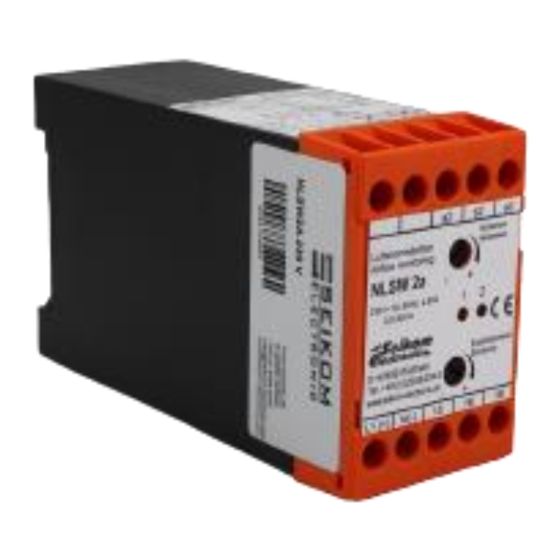
Summary of Contents for Seikom Electronic NLSW 2a
- Page 1 Operating instructions NLSW®2a 24 V AC/DC, 230 V AC Version 1...
- Page 2 Page: 2 +49 2058 916 900 0• info@seikom-electronic.com• www.seikom-electronic.com...
-
Page 3: Table Of Contents
Operating instructions NLSW®2a Contents Contents ..........................3 1. SAFETY INSTRUCTIONS ....................4 2. GENERAL INFORMATION ....................4 2.1 Proper use ..........................4 2.2 Operating principle ........................4 3. TECHNICAL DATA ......................5 4. INSTALLATION AND COMMISSIONING ................6 4.1 Installation conditions ......................6 4.2 Electrical connections ...................... -
Page 4: Safety Instructions
Operating instructions NLSW®2a 1. SAFETY INSTRUCTIONS Read the product description before operating the unit. Make sure that the product is fully suitable for your application. Improper or unintended use can lead to malfunctions of the unit or undesirable effects on your application. -
Page 5: Technical Data
Operating instructions NLSW®2a 3. TECHNICAL DATA Type NLSW®2a Item no. 66224 56558 Operating voltage 24 V AC/DC 230 V AC Voltage tolerance ± 5% Overvoltage category Signal display voltage Green LED Power consumption max. 3 VA W 4.5 VA W Ambient temperature unit -20 ... -
Page 6: Installation And Commissioning
Operating instructions NLSW®2a 4. INSTALLATION AND COMMISSIONING Installation and commissioning must be carried out by authorised and qualified personnel. The connection to the main supply (L, N) must be made via a protected disconnector with standard fuses. Basically, the general VDE regulations must be observed (VDE 0100, VDE 0113, VDE 0160). If the potential-free contact is connected to a protective extra-low voltage, the connecting cables up to the terminal must be sufficiently insulated, otherwise the double insulation to the mains voltage side may be impaired. -
Page 7: Electrical Connections
Operating instructions NLSW®2a 4.2 Electrical connections Colour code: BN=brown BK=black GR=grey 4.3 Setting the switching point The relationship between flow velocity and resistance change is not linear. In the lower range (small flows) the change in resistance is very large. In the upper range, the change in resistance becomes smaller and smaller for the same flow changes. -
Page 8: Maintenance Instructions
Operating instructions NLSW®2a The following procedure is recommended when commissioning and adjusting the unit: ▪ Install and connect the flow controller according to the installation instructions and conditions. ▪ Connect suitable sensor. (F2, F3, F4.x, F9 sold separately) Please note: Reversed sensor connections lead to malfunctions and possible damage. - Page 9 Operating instructions NLSW®2a The unit does not detect The sensor is not installed Check that the sensor has airflow. properly. been installed so that its mark is in the direction of the airflow source and close to the centre of the duct. Flow is outside the measuring Adjust the diameter of the range...
-
Page 10: Eu Declaration Of Conformity
Operating instructions NLSW®2a 7. EU DECLARATION OF CONFORMITY Page: 10 +49 2058 916 900 0• info@seikom-electronic.com• www.seikom-electronic.com... - Page 12 Growing network of local distributors available online www.seikom-electronic.com Our product portfolio Flow rate Temperature Print Air quality and CO Zener barriers Universal transmitter +49 2058 916 900 0 info@seikom-electronic.com www.seikom-electronic.com SEIKOM-Electronic GmbH & Co KG Gold-Zack-Strasse 7 40822 Mettmann...


Need help?
Do you have a question about the NLSW 2a and is the answer not in the manual?
Questions and answers