Table of Contents
Advertisement
Quick Links
Advertisement
Table of Contents

Subscribe to Our Youtube Channel
Related Manuals for Seikom Electronic RLSW 4A


Summary of Contents for Seikom Electronic RLSW 4A
- Page 1 Operating instructions RLSW®4A (M8) 24 V AC/DC, 230 V AC Version 1...
- Page 2 Page: 2 +49 2058 916 900 0 - info@seikom-electronic.com - www.seikom-electronic.com...
-
Page 3: Table Of Contents
Operating instructions RLSW®4A (M8) Contents Contents ............................3 1. SAFETY INSTRUCTIONS......................4 2. GENERAL INFORMATION ....................... 4 2.1 Proper use .............................. 4 2.2 Functional principle ..........................4 3. TECHNICAL DATA ........................5 3.1 Dimensions RLSW®4A (permanently installed sensor) ................6 4. -
Page 4: Safety Instructions
Operating instructions RLSW®4A (M8) 1. SAFETY INSTRUCTIONS Read the product description before using the device. M a k e s u r e that the product is fully suitable for your application. Incorrect or improper use can lead to malfunctions of the device or to undesirable effects on your application. -
Page 5: Technical Data
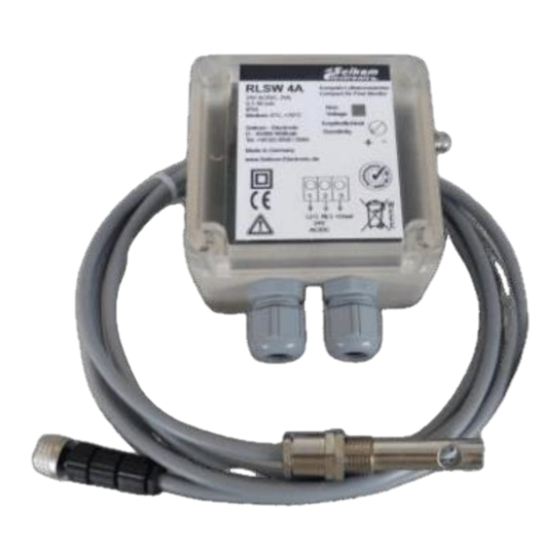
Operating instructions RLSW®4A (M8) 3. TECHNICAL DATA Type RLSW®4A RLSW®4A M8 Article no. 74825A (24 V AC/DC) 74825AM8 (24 V AC/DC) Operating voltage 24 V AC/DC Voltage tolerance ± 5% Overvoltage category Signal display, voltage Green LED Power consumption max. 3 VA Ambient temperature Device -20 ... -
Page 6: Dimensions Rlsw®4A (Permanently Installed Sensor)
Operating instructions RLSW®4A (M8) 3.1 Dimensions RLSW®4A (permanently installed sensor) 4. INSTALLATION AND COMMISSIONING Installation and commissioning must be carried out by authorized and qualified personnel. The connection to the main supply (L, N) must be made via a protected circuit breaker with standard fuses. The general VDE regulations must always be observed (VDE 0100, VDE 0113, VDE 0160). -
Page 7: Electrical Connections
Operating instructions RLSW®4A (M8) 4.2 Electrical connections 4.3 Setting the switching point The relationship between the air velocity and the change in resistance of the precision resistors is not linear. In the lower range (low flow velocities), the relative change in resistance is large. In the upper range, the change in resistance becomes smaller and smaller with the same deviation in flow velocity. -
Page 8: Maintenance Instructions
Operating instructions RLSW®4A (M8) ▪ To check the function of the flow regulator, reduce or stop the flow. ▪ The yellow LED goes out (output relay on the RLSW5 has dropped out) The device is now ready for operation. 5. MAINTENANCE INSTRUCTIONS The air flow sensor should be serviced at regular intervals, i.e. -
Page 9: Error Messages
Operating instructions RLSW®4A (M8) 6. ERROR MESSAGES The following instructions are intended as first aid if your airflow monitor is not working properly. Problem Possible cause Solution The device does not work. Missing or incorrect Supply voltage and Power supply. Check the connection. -
Page 10: Eu Declaration Of Conformity
Operating instructions RLSW®4A (M8) 7. EU DECLARATION OF CONFORMITY +49 2058 916 900 0 - info@seikom-electronic.com - www.seikom-electronic.com Page: 10... - Page 12 Growing network of local distributors available online www.seikom-electronic.com Our product portfolio Flow rate Temperature Pressure Zener barriers Air quality and CO Universal Transmitter +49 2058 916 900 0 info@seikom-electronic.com www.seikom-electronic.com SEIKOM-Electronic GmbH & Co KG Gold-Zack-Straße 7 40822 Mettmann...
Need help?
Do you have a question about the RLSW 4A and is the answer not in the manual?
Questions and answers