Table of Contents
Advertisement
Quick Links
Advertisement
Table of Contents

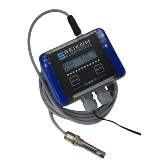
Summary of Contents for Seikom Electronic RLSW 9
- Page 1 User Manual RLSW®9 24 V DC Version 1...
- Page 2 Page: 2 +49 2058 916 900 0 | info@seikom-electronic.com | www.seikom-electronic.com...
-
Page 3: Table Of Contents
User Manual RLSW®9 Contents Contents ..........................3 1. SAFETY INSTRUCTIONS ....................4 2. GENERAL INFORMATION ....................4 2.1 Proper use ..........................4 2.2 Operating principle ........................4 3. TECHNICAL DATA ......................5 3.1 Dimensions ..........................7 4. INSTALLATION AND COMMISSIONING ................8 4.1 Installation conditions ...................... -
Page 4: Safety Instructions
User Manual RLSW®9 1. SAFETY INSTRUCTIONS Read the product description before commisioning the device. Make sure that the product is fully suitable for your application without any restrictions. Improper use can lead to malfunctions of the device or to undesirable effects on your application. For this reason, installation, electrical connection, commissioning, operation and maintenance of the device may only be carried out by trained personnel. -
Page 5: Technical Data
User Manual RLSW®9 3. TECHNICAL DATA Type RLSW®9 RLSW®9 M8 Device type Compact device with perma- Separate sensor and electron- nently mounted sensor ics connected by cable Article no. 1362Fx 1362FxM8 Operating voltage 24 V DC Voltage tolerance 20 ... 36 V DC Overvoltage category Voltage signal display Mains available, green LED... - Page 6 User Manual RLSW®9 Increased operational reliability for your machine/system thanks to continuous monitor- ing of the sensor, the sensor elements and the connecting cable for short circuits and wire breaks during operation. In addition, the electronics are continuously monitored by internal test routines.
-
Page 7: Dimensions
User Manual RLSW®9 3.1 Dimensions +49 2058 916 900 0 | info@seikom-electronic.com | www.seikom-electronic.com Page: 7... -
Page 8: Installation And Commissioning
User Manual RLSW®9 4. INSTALLATION AND COMMISSIONING Installation and commissioning must be carried out by authorised and qualified personnel. The connection to the main supply (L, N) must be made via a protected circuit breaker with standard fuses. The general VDE regulations must always be observed (VDE 0100, VDE 0113, VDE 0160). If the potential-free contact is connected to a safety extra-low voltage, the connecting cables must be suf- ficiently insulated up to the terminal, as otherwise the double insulation to the mains voltage side may be impaired. -
Page 9: Electrical Connections / Terminal Assignment
User Manual RLSW®9 4.2 Electrical connections / terminal assignment The electrical connections are located in the housing under the cover with the membrane keypad. The cover is opened by inserting a flat, approx. 4 mm wide screwdriver into the slot on the right and then pushing the screwdriver slightly inwards/leftwards. -
Page 10: Setting The Switching Point
User Manual RLSW®9 Flow/current current output minus 4 ... 20 mA Flow/current current output plus 4 ... 20 mA Relay contact NC contact NC ('normally closed') Relay contact centre /Common contact COM ('common') Relay contact NO contact NO ('normally open') Voltage outputs 0 ... - Page 11 User Manual RLSW®9 Further switching point setting options 1 (optional): Relative If the switching point is set to "flow%" under menu item 4: "Alarm", you will be prompted to set a number between 1 and 99 when you press Menu/T1. This number corresponds to the switch- ing point as a percentage of the set maximum flow, e.g: Maximum flow = 10 m/s, switching point 50%, real switching point is then 5 m/s.
-
Page 12: Menu Settings
User Manual RLSW®9 4.4 Menu settings You can access the setting mode by pressing and holding (approx. 3 s) the "Menu" button on the cover or T1 in the appliance itself. Please note that the number and type of menu items may vary depending on the specification and design. -
Page 13: Presentation Of The Measurement Results On The Display
User Manual RLSW®9 To finalise the changes, exit the menu under "Display ok" with "Save and exit", otherwise the data will be lost. If the dimension of the display is changed (e.g. from m/s to l/min), it is essential to readjust the switching threshold and, if necessary, the measuring range. - Page 14 User Manual RLSW®9 Information on the RLSW®9 M8 with remote sensor The RLSW®9 is also available with a remote sensor. The supplied sensor has a connection cable with a length of 2.5 metres as standard (special lengths are available on request). This length must not be changed due to the calibration.
-
Page 15: Maintenance Instructions
User Manual RLSW®9 5. MAINTENANCE INSTRUCTIONS The air flow sensor should be serviced at regular intervals, i.e. that when used in heavily the air flow sensor is cleaned if the media is contaminated. The following procedure is expedient: ▪ Dismantling the airflow monitor ▪... - Page 16 User Manual RLSW®9 Turn the potentiometer Device switches when the The temperature gradient is slightly further clockwise. media temperature rises rap- outside the technical specifi- Set the switching point in a idly. cations. hot media environment. Page: 16 +49 2058 916 900 0 | info@seikom-electronic.com | www.seikom-electronic.com...
-
Page 17: Eu Declaration Of Conformity
User Manual RLSW®9 7. EU DECLARATION OF CONFORMITY +49 2058 916 900 0 | info@seikom-electronic.com | www.seikom-electronic.com Page: 17... - Page 18 User Manual RLSW®9 Page: 18 +49 2058 916 900 0 | info@seikom-electronic.com | www.seikom-electronic.com...
- Page 20 Growing network of local distributors available online www.seikom-electronic.com Our product portfolio Flow rate Temperature Pressure Air quality and CO Zener barriers Universal Transmitter +49 2058 916 900 0 info@seikom-electronic.com www.seikom-electronic.com SEIKOM-Electronic GmbH & Co KG Gold-Zack-Straße 7 40822 Mettmann...


Need help?
Do you have a question about the RLSW 9 and is the answer not in the manual?
Questions and answers