Table of Contents
Advertisement
Quick Links
Advertisement
Table of Contents

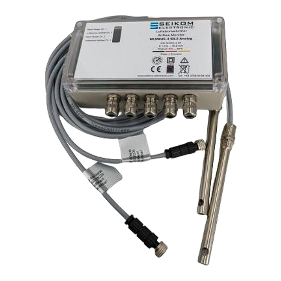
Summary of Contents for Seikom Electronic NLSW 45-3 SIL2 Analog
- Page 1 Operating instructions NLSW®45-3 SIL2 Analog 24 V AC/DC, 230 V AC Version 1...
- Page 2 Page 2 +49 2058 916 900 0• info@seikom-electronic.com• www.seikom-electronic.com...
-
Page 3: Table Of Contents
Operating instructions NLSW®45-3 SIL2 Analog CONTENTS CONTENTS ..........................3 1. SAFETY INSTRUCTIONS ....................5 2. GENERAL INFORMATION ....................5 2.1 Field of application and practical use ..................5 2.2 Outputs ..........................5 3. TECHNICAL DATA ......................6 3.1 Device dimensions ........................7 4. - Page 4 Operating instructions NLSW®45-3 SIL2 Analog Page 4 +49 2058 916 900 0• info@seikom-electronic.com• www.seikom-electronic.com...
-
Page 5: Safety Instructions
Operating instructions NLSW®45-3 SIL2 Analog 1. SAFETY INSTRUCTIONS Please read the product description carefully before using the device. Make sure that the product is fully suitable for your application. Improper use can lead to malfunctions of the device or to undesirable effects on your application. For this reason, installation, electrical connection, commissioning, operation and maintenance of the de- vice may only be carried out by trained personnel. -
Page 6: Technical Data
Operating instructions NLSW®45-3 SIL2 Analog 3. TECHNICAL DATA Type NLSW®45-3 SIL2 Analog NLSW®45-3 SIL2 Analog 24 V AC/DC 230 V AC Item number 1145SIL2 1147SIL2 Operating voltage 24 V AC/DC 230 V AC 50/60 Hz Voltage tolerance ± 10% ± 10% Overvoltage category Signal lamp Voltage Green LEDs... -
Page 7: Device Dimensions
Operating instructions NLSW®45-3 SIL2 Analog 3.1 Device dimensions 4. INSTALLATION AND COMMISSIONING Installation and commissioning must be carried out by authorized and qualified personnel. 4.1 Installation conditions of the airflow sensors The following installation conditions must be observed for the F3.x SIL2 sensor: ▪... -
Page 8: Installation
Operating instructions NLSW®45-3 SIL2 Analog ▪ Each sensor is calibrated for its channel and should be connected to this channel. ▪ If the sensor cable is laid in a duct together with other live cables (e.g. motors or solenoid valves), we recommend shielding the sensor cable (connect a shield). Sensors with shielded cables are available as accessories from SEIKOM. -
Page 9: Commissioning The Device
Operating instructions NLSW®45-3 SIL2 Analog Color code: GY=grey | BK=black | BN=brown 4.4 Commissioning the device The following sequence must be observed when commissioning and adjusting the devices: Mounting the sensors in the air duct Connecting the sensors to the NLSW®45-3 SIL2 Analog (see section 4.4.1) Connecting the electrical connections to the outputs of the NLSW®45-3 SIL2 Analog Checking the electrical connections Connecting the mains voltage... -
Page 10: Connecting The Sensors To The Nlsw®45-3 Sil2 Analog
Operating instructions NLSW®45-3 SIL2 Analog The four potentiometers (purple) fixed with protective lacquer are set at the factory and must not be adjusted. The steps for commissioning and setting the device are described below. 4.4.1. Connecting the sensors to the NLSW®45-3 SIL2 Analog Connect two suitable sensors (F3.x SIL2) to the device using the supplied terminals;... -
Page 11: Adjusting The Settings On The Nlsw®45-3 Sil2 Analog
Operating instructions NLSW®45-3 SIL2 Analog 4.4.2. Adjusting the settings on the NLSW®45-3 SIL2 Analog Set the "Sensitivity" potentiometer [Sense] (dark blue) for both channels to the left stop (in- sensitive). Set the "Start-up delay" potentiometer [Delay] (orange) for both channels to the desired start-up delay time of approx. -
Page 12: Typical Output Values
Operating instructions NLSW®45-3 SIL2 Analog Check the flow setting with the PLC by changing or switching off the air flow. Please note that the analog outputs Iout and Uout are not linear. If you adjust the measuring range of the device, please remember to adjust the current and voltage values stored in the PLC. -
Page 13: Switching Point Adjustment
Operating instructions NLSW®45-3 SIL2 Analog The media temperature only has a small influence on the current or voltage output and switching point. Please take this influence into account when commissioning and setting the measuring device by setting the devices in normal operating mode. 4.6 Switching point adjustment When setting the switching point, it should be noted which change is to be monitored, as different settings have their own advantages and disadvantages. - Page 14 Operating instructions NLSW®45-3 SIL2 Analog Recom- Type of Definition of mended inter- examination Visual inspec- A visual inspection is an inspection in which visible faults Monthly tion are detected without the use of access equipment or tools, for example damage to the sensor or dust deposits. Close-up in- A test in which, in addition to the aspects of the visual in- Every 6 mon-...
-
Page 15: Troubleshooting
6. TROUBLESHOOTING The following instructions are intended to help you if your airflow monitor is not working properly. If you have any further questions, the SEIKOM Electronic team will be happy to help you at any time by phone or e-mail. -
Page 16: Disposal
Operating instructions NLSW®45-3 SIL2 Analog NLSW®45-3 SIL2 Analog has Sensor is heavily soiled by the Carefully clean the sensor modified response behavior medium (deposits on the sen- with water. sor) Never use hard objects for cleaning. NLSW®45-3 SIL2 Analog Temperature gradient is out- Check the temperature gradi- switches in the event of a side the specification... - Page 17 Operating instructions NLSW®45-3 SIL2 Analog +49 2058 916 900 0• info@seikom-electronic.com• www.seikom-electronic.com Page 17...
-
Page 18: Eu Declaration Of Conformity
Operating instructions NLSW®45-3 SIL2 Analog 8. EU DECLARATION OF CONFORMITY Page 18 +49 2058 916 900 0• info@seikom-electronic.com• www.seikom-electronic.com... - Page 19 Operating instructions NLSW®45-3 SIL2 Analog +49 2058 916 900 0• info@seikom-electronic.com• www.seikom-electronic.com Page 19...
- Page 20 Growing network of local distributors available online www.seikom-electronic.com Our product portfolio Flow rate Temperature Print Air quality and CO Zener barriers Universal Transmitters +49 2058 916 900 0 info@seikom-electronic.com www.seikom-electronic.com SEIKOM-Electronic GmbH & Co KG Gold-Zack-Straße 7 40822 Mettmann...


Need help?
Do you have a question about the NLSW 45-3 SIL2 Analog and is the answer not in the manual?
Questions and answers