
Related Manuals for urmet domus PRO 1098


Summary of Contents for urmet domus PRO 1098
- Page 1 Mod. 1098 DS1098-038C NVR H.265 WITH HDMI NVR 4K H.265 SERIES PRO 4 channels Ref. 1098/324P 8 channels Ref. 1098/328P 16 channels Ref. 1098/326P 32 channels Ref. 1098/334 USER MANUAL...
-
Page 2: Table Of Contents
ENGLISH TABLE OF CONTENTS General information ..........................6 Product Description ........................6 General Features ............................6 Opening the package ........................8 Contents of the package ..........................8 Warnings ...........................9 Power................................9 Safety precautions ............................9 Installation precautions ..........................9 Cleaning the device ............................9 Hard disk ............................... - Page 3 Thermal ............................... 47 Combination Alarm ............................. 48 PTZ Linkage ............................... 49 Exception ..............................50 Alarm Schedule ............................50 Voice Prompts............................. 51 3.7.9.1 File Management ............................. 51 3.7.9.2 Loop Management ........................... 52 Deterrence ..............................52 Siren ................................55 Disarming ..............................55 AI ............................
- Page 4 3.10.6.1 Onvif ..............................132 3.10.6.2 RTMP ..............................132 3.11 Device ........................... 133 Disk Manage ............................. 133 3.11.1.1 Disk Manage ............................133 3.11.1.2 Disk Group Only available for the 1098/334 ................... 134 3.11.1.3 S.M.A.R.T. (Self-Monitoring, Analysis and Reporting Technology) information ........135 Cloud ................................
- Page 5 AI ................................195 Alarm Set (Allarme) ........................... 213 Network ..............................218 Device ............................... 224 System ..............................226 Local Setting ......................... 235 Logout ........................... 236 NVR Specifications Ref. 1098/324P-1098/328P-1098/326P (Pal format).......... 237 NVR Specifications Ref. 1098/334 (PAL format) ................238 Maximum recording time with 2000GB Hard Disk ................240 Ref.
-
Page 6: General Information
GENERAL INFORMATION Dear Customer, Thank you for purchasing this product. This quick start guide was written to help you set up the NVR Series PRO URMET S.p.A, Ref. 1098/324P - Ref. 1098/328P - Ref. 1098/326P – Ref. 1098/334 models rapidly and easily. Carefully read this manual which contains information for correct, safe use. - Page 7 The main features are summarised in the following table: DS1098-038C...
-
Page 8: Opening The Package
Function Description Double video output with monitor, VGA virtual output port or HDMI Output; Support Live URMET UVS Client Software and MP live surveillance and also support zoom in/out, auto sequence and PIP display. Video compression standard: H.265; adjustable recording quality, resolution and Record frame rate;... -
Page 9: Warnings
WARNINGS POWER ➢ Check mains rating before plugging the power unit in. ➢ Do not pull the cord to unplug the device. ➢ Switch the device off before unplugging power unit. This operation must not be performed when the NVR Boost is recording or playing or when the configuration menu is open. - Page 10 ➢ Product users shall be responsible for checking and respecting all local rules and regulations concerning monitoring and recording video signals. The manufacturer SHALL NOT BE LIABLE for use of this product not in compliance with the laws in force. For more information see the website http://www.garanteprivacy.it DS1098-038C...
-
Page 11: Description Of The Parts
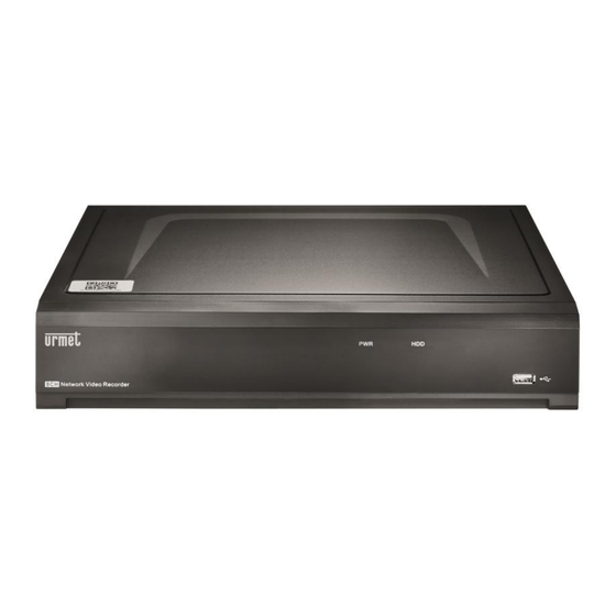
DESCRIPTION OF THE PARTS FRONT PANEL NVR stands for Network Video Recorder Equipment. FRONT PANEL NVR REF. 1098/324P, 1098/328P, 1098/326P, 1098/334. Writing or Number Symbol Function and description indicator Power indicator The green LED on means that the NVR is powered correctly. The red LED blinking means that the user is reading or writing on Hard disk the hard disk. -
Page 12: Rear Panel Nvr Ref. 1098/326P
REAR PANEL NVR REF. 1098/326P REAR PANEL NVR REF. 1098/334 Number Physical port Connection method Power switch Power on and off Power connector Power connector Sensor/Alarm Alarm or for alarm device connector USB 2.0 port USB device connector, e.g. USB mouse (2 USB 3.0 for 1098/334) HDMI port High-definition HDMI port ( VGA port... -
Page 13: Sensor/Alarm Functions
SENSOR/ALARM FUNCTIONS ➢ Alarm input: Connect signal [-] of the sensor to pin G (GND) and the signal [+] to the input of channel 1...16 as alarm device. ➢ Alarm output: Connect to the two ports marked with “ALARM OUT” OPERATION WITH MOUSE The mouse must be used to operate the system. -
Page 14: Osd Nvr Menu Settings
OSD NVR MENU SETTINGS After having plugged in the NVR, the system will run the initialisation procedures during which the following image will appear: At the end of the boot-up, the NVR will switch to Live view. FIRST NVR LOGIN For the first time when you run the NVR, you must be required to set your own password immediately in order to protect your privacy. -
Page 15: Wizard Menu
NOTE: If you forget your password, you can reset it via the hole (RESET) located at the rear of the NVR. Pressing it should last 10 seconds after which there is an audible warning (3 beeps) and the device restarts. This operation will also reset the device to factory settings. -
Page 16: Live Interface And Pop-Up Menu
LIVE INTERFACE AND POP-UP MENU Task Menu Camera title To display the camera title: IP: This indicates that the camera connected is an IP camera Status icons This indicates that the NVR is currently recording. This icon appears when the camera has detected motion. This icon appears when the camera has detected PIR event. - Page 17 Click to edit the current IP camera. DS1098-038C...
-
Page 18: Taskbar
TASKBAR Click to open the Main Menu. Click to pop up the shutdown options pop-up box. Click to select different layout for live view. Press to select a different layout for live display (only available for the 1098/334) Click to select more layouts for live view. Click to start viewing channels in a sequence. -
Page 19: Shutdown / Reboot / Lock Screen Menu
Press to enable the camera siren (where applicable) by setting its sound intensity. Press to enable two-way audio communication. Add customized tag: see the respective section for more information. SHUTDOWN / REBOOT / LOCK SCREEN MENU Click on the Shutdown button on the Taskbar and the check the further action you want to move. -
Page 20: Ptz Control
PTZ CONTROL After finishing the PTZ setup, you can use the PTZ function to control your PTZ camera. Left-click on a channel in the Live Viewing screen to open the Camera Quick Toolbar and select the PTZ control icon PTZ control panel will be displayed. Icon Description Channel... -
Page 21: Cruise Set
CRUISE SET Open Auto Cruise function on PTZ setting menu if you want to setup cruise function (system default: off), and set up Cruise channel, Cur point and total quantity and stop time etc. How to set a preset point: •... - Page 22 Click on to view then click on . Set the Tag once, the Tag can record one minute, this is the default setting. Tag name may be edited, for example: Warning: User can select [General], [Sub-periods] and [Smart] options on the [Search] page and set the Tag event record. DS1098-038C...
-
Page 23: To Search For A Tag Record Event
TO SEARCH FOR A TAG RECORD EVENT Click on Start Menu→ Setup → Search → Tag on the Tag event search page, then set Start Time, End Time, and Channel. Click on to view the list of event tags. Playback: Click on to play the Tag recording event. -
Page 24: Main Menu
MAIN MENU All the NVR functions can be accessed from the Main Menu. If you have not logged in (main menu locked mode), you will need to enter Username and Password as shown in the following figure: For System Login press Unlock button. Pressing the Pattern button will allow access to the main menu via the unlocking pattern if it was set during the first access. -
Page 25: Ip Channels
3.5.1.1 IP Channels The IP cameras are configured by selecting IP Channels on the side menu. Click on [Search] to search IP cameras from local network. Press [Add All] to quickly add IP cameras present in the NVR LAN (the IP address is assigned automatically is this case). - Page 26 • IP Address/Domain: IP address or domain name of the IP camera. • Alias: IP camera name. • Position: Position in which to display the camera name on the screen. • Port: Port of the IP camera. • Protocol: Select the protocol of the IP camera from the drop-down menu. •...
- Page 27 Power over Ethernet or POE is the mode for powering electronic equipment through the network wire. The POE Power section deals with the management of camera power through Ethernet ports. Up to 100 metres of Ethernet cable can be used in POE mode. Between 100 metres and 230 metres of Ethernet cable each PoE port on the NVR can support an output bandwidth of up to 10 Mbps and EPOE (Extended POE) mode must be used.
- Page 28 Confirm to quit at this point. Now, the IP camera detected using the protocol employing the RTSP port can be added to the live grid of the NVR. DS1098-038C...
-
Page 29: Poe Power
POE Power 3.5.1.2 Power over Ethernet or POE is the mode for powering electronic equipment through the network wire. The POE Power section deals with the management of camera power through Ethernet ports. LIVE This page of the Display menu can be used to configure the parameters related to the <Live> screen of the NVR. As shown in the following figures, the available options may be different if an IP camera (figure on the right) is being configured. -
Page 30: Image Control
Here are the details related to other functions: Select a channel to be configured. Attribute a name to the camera. Date format to be displayed for the camera (for IP camera only). Time format to be displayed for the camera (for IP camera only). Monitor refresh rate (50 Hz or 60 Hz). -
Page 31: Ptz
Select a channel to be configured. Select the desired integrated IR cut filter mode to ensure the camera works correctly in D/N. Set the IR-CUT switching delay time. Set the infrared illuminator. Check to enable lens flip, angle flip and corridor mode. Set the flip angle. -
Page 32: Video Cover Settings (Privacy Zone)
VIDEO COVER SETTINGS (PRIVACY ZONE) This menu allows you to create privacy zones if you want to partially cover some certain part of the image. You can create up to four privacy zones in any size and location on the camera image. Enable the Privacy Zone, and select how many zones you need. -
Page 33: Pir
Motion Detection Area: The whole screen is marked for motion detection (red blocks) as default. If you want to disable the motion detection on a certain area, click on the grid cursor and then drag the mouse to highlight the scope to deselect the area into transparent blocks. -
Page 34: Roi
Click on to set the system to automatic motion detection of PIR function. You can set an area for motion detection PIR function by clicking on: To configure PIR Alarm, see "Section 3.7.2- PIR Notification” The ROI function allows you to configure certain parameters related to an area of particular interest. For example, it is possible to choose to save a high-resolution video stream for a portion of the image while leaving a lower resolution for the remaining part of the image. - Page 35 Define an application channel for the function. Select Setup to define the zone. Hold down the left mouse button and drag an ROI zone. Stream Type: You can define the type of video stream to be saved for the ROI zone. Region ID: A maximum of 8 ROI zones can be set per channel.
-
Page 36: Thermal
THERMAL To select Thermal in the side menu to setup a thermal camera. DS1098-038C... -
Page 37: Record Settings
RECORD SETTINGS This subsection describes the configuration of the recording options made available by the NVR: ➢ Encode ➢ Record ➢ Capture ENCODE This menu can be used to configure the quality of video recording or network transmission images. As a rule, Mainstream defines the recording video quality which will be saved on the HDD, while Substream defines the video quality which is being viewed via remote access (e.g. -
Page 38: Record
Select Predefined mode to select the default bitrate. • Bitrate: This parameter corresponds to the speed of data transfer that the HVR will use to record video. Recordings that are encoded at higher bitrates will be of better quality. • Audio: you can enable/exclude audio recording for each channel. -
Page 39: Record Schedule
3.6.2.2 Record Schedule This menu can be used to set the NVR video recording program and define the recording mode for each channel. It can be used to define a daily and hourly schedule in normal (continuous) recording mode, motion recording, I/O alarm recording and PIR recording (if supported by NVR). -
Page 40: Capture
CAPTURE This subsection of the Parameters menu can be used to configure the parameters dedicated to the acquisition of images in alarm conditions and to the programming of the time slots during which the function must be active. 3.6.3.1 Capture The Capture item is used to configure the parameters for recording images in an alarm condition;... -
Page 41: Alarm Configuration
• Channel: This can be used to select the channel to set the recording parameters. • Normal: A green time slot indicates that normal recording is set for the channel for the time slot • Motion: A yellow time slot indicates that the channel records only when a motion is detected during the time slot. •... - Page 42 • Full screen: This can be used to set displaying the video in full screen mode when Motion is detected. • Voice Prompts: This menu allows voice prompts to be set according to time periods: each alarm can support up to 12 time periods.
-
Page 43: Pir Notification
PIR NOTIFICATION This is an optional function which appears if the camera supports the PIR sensor; PIR alarm devices with external sensor must be connected. Select PIR in the side menu to open a page where to define the methods and actions to be taken in case of PIR alarm detection. - Page 44 • PIR Detection: Click on PIR Detection and then click on setup to configure the motion detection PIR function: • : Show the IP channel • :configure monitor area for PIR • You can set an area for motion detection PIR function by clicking on: DS1098-038C...
-
Page 45: I/O Alarm Settings
• Copy: This can be used to copy current channel parameters to any other channel or to all channels. • Default: This can be used to restore the default alert settings. I/O ALARM SETTINGS On this page, it is possible to configure alarm notification from an input of the NVR's I/O interface. •... - Page 46 • Voice Prompts: This menu allows you to set voice prompts based on time periods: each alarm can support up to 12 time periods. DS1098-038C...
-
Page 47: Thermal
THERMAL Read the description under the following figures for this menu page: At this point, the alarms can be set according to the different states. Here is a brief description: • Channel: you can select the channel for thermal camera. •... -
Page 48: Combination Alarm
COMBINATION ALARM Combined alarm and notification can be set per channel. Here is a brief description: • Channel: This can be used to select the channel with which the fuction of combination alarm is associated. • Enable Alarm: Enables the combined alarm. •... -
Page 49: Ptz Linkage
• Copy: This can be used to copy current channel parameters to any other channel or to all channels. • Default: This can be used to restore the default alert settings. • Apply to save the changes. PTZ LINKAGE A connection may be established between a Speed Dome Camera (if present) and the Motion Detection alarm. This function can be used to move the Speed Dome Camera to the associated preset point when a motion alarm is triggered. -
Page 50: Exception
EXCEPTION This menu can be used to set the event type (e.g. full HDD, disk error, video loss) for which you want to be alerted about by the NVR. Here is a brief description: • Event Type: Select the event type from the following options: No Space on Disk: When an HDD is full. -
Page 51: Voice Prompts
Here is a brief description: • Alarm Out: This can be used to set the alarm output program in case of an event. • Push: Set the program for push notifications to a mobile device in case of an event. •... -
Page 52: Loop Management
Local: Local transmission. When this transmission mode is chosen, the audio output is connected to the side of the device. IPC: transmission from network camera. Choosing this transmission mode requires that the camera supports the voice transmission function and has an audio output. It is possible to set voice messages according to time periods: each alarm can support up to 12 time periods. - Page 53 Channel: Camera name. Setup: Press to set the parameters of the deterrence function. Channel: Select the camera you wish to configure. Light Switch: Press to enable light signalling. Light Level: The light intensity can be set. Light Duration: The duration of the light signal can be set. Colour Image: Only active for cameras with warm lights.
- Page 54 Deterrence Schedule: by pressing on you can access the hourly schedule of the deterrence function. Apply: To save the settings. Default: to reset settings to factory defaults. DS1098-038C...
-
Page 55: Siren
SIREN The siren function allows you to configure the acoustic warning of abnormal behaviour detected by the camera. This function is only supported for cameras with a siren. Channel: Select camera. Enable: Press to enable the function. Siren Level: Set the intensity of the siren sound. Siren Duration: Set the duration of the siren in seconds. - Page 56 Apply: To save the settings. Default: to reset settings to factory defaults. DS1098-038C...
-
Page 57: Setup
This section can be used to set up intelligent analysis, i.e. systems which generate descriptions of what is happening in the video stream. The submenu is: Setup Recognition Alarm Statistics SETUP 3.8.1.1 Face Detection This function detects the faces of moving people appear in a predefined area. Select Switch ON and then Apply to enable face recognition. -
Page 58: Pd & Vd Pedestrian & Vehicle Detection
• Channel: Select the channel you want to configure. • IVA Lines: Enable or disable the IVA Lines. • Snap Mode: This can be used to select Real Time mode / Optimal mode / Interval mode. By selecting Interval mode, you can set Snap Num 1 ~ 3 and change the Snap interval time •... - Page 59 • Channel: This can be used to select the channel to be configured. • Switch: Enable/Disable the PD & VD function. • Level: Level (Low/Middle/High - Low/Middle/High). Low level is recommended for detecting long-range objects. High level is recommended for detecting short-range objects. •...
-
Page 60: Pid Perimeter Intrusion Detection
• IVA Lines: enable or disable IVA Lines. • Snap Mode: to select Real Time Mode / Interval Mode, select Interval Mode, you can set Snap Num 1~3 or unlimited (unlimited), you can change the Snap interval time from 1 to 255 •... - Page 61 ➢ Choose a Rule Number. This is the number of the PID area. A maximum of 4 areas can be set for the PID function. ➢ Enable detection in Rule Switch. ➢ Choose Rule Type. A→B: The NVR will only detect action from side A to side B; B→A: The NVR will only detect action from side B to side A;...
-
Page 62: Lcd Line Crossing Detection
LCD Line Crossing Detection 3.8.1.4 This function detects people, vehicles or other objects crossing a predefined virtual line; when the alarm is triggered, certain actions can be taken. • Channel: select the channel to be configured • Switch: enable or disable the LCD function. •... -
Page 63: Cc Cross Counting
To change the position or length of the line, click on the red box: the line will turn red. Hold down the left mouse button to move the line or drag its ends to change the length or position of the line. To delete one or more lines from the camera image, click on the red box, then click on the Remove button. - Page 64 Choose a Rule Number. This is the maximum number of lines that can be drawn. Maximum 4 lines. Enable detection in Rule Switch. Choose Rule Type. Using the mouse, click on 2 points on the camera image to draw a virtual line. From side A to side B, this is an input; from side B to side A, this is an output.
-
Page 65: Hm Heat Map
HM Heat Map 3.8.1.6 This menu allows you to set the rules for the areas with the most visitors. Switch: enables and disables the heat map function. Setup: Press to draw the virtual area on the image. Channel: Select the channel to be configured. Rule Number: Select the rule number representing the number of heat map detection areas. -
Page 66: Cd Crowd Density Detection
CD Crowd Density Detection 3.8.1.7 This menu allows you to set the rules for detecting crowding in a specific area. Switch: Enables and disables the crowd detection function. Sensitivity: A value between 1 and 4 can be chosen. The higher the value the more sensitive the detection will be. Setup: Press to draw the virtual area on the image. -
Page 67: Qd Queue Length Detection
Save: Press Save to confirm the configured settings. QD Queue Length Detection 3.8.1.8 This menu allows you to set the rules for detecting the length and dwell time of the queue in a specific area. Switch: Enables and disables the crowd detection function. Sensitivity: A value between 1 and 4 can be chosen. -
Page 68: Lpd License Plate Detection - Beta Version
Rule Switch: Enables or disables the rule. Visible Area: Decide whether or not to display the crowd detection area. Remove: Press on the detection area box and press Remove to delete the area. Remove All: Press Remove All to delete the detection box directly. Save: Press Save to confirm the configured settings. -
Page 69: Rsd Rare Sound Detection
- Interval Mode: The maximum number of times and the interval for sending each image to the device can be set. Snap number: The number of push images per number plate detection can be set from 1, 2, 3 up to unlimited, i.e. send images to the device one, two, three or infinitely many times. -
Page 70: Sod Stationary Object Detection
Channel: Choose the channel to be configured. Sensitivity: The higher the value, the more sensitive the detection. The value can be set from 1 to 100. Detection Type: Three types of sounds can be chosen: baby crying, dog barking and gunshot. - Baby Crying Sound: Check the box to activate cry detection - Dog Barking: Check the box to activate barking dog detection. -
Page 71: Sound Detection
- Channel: Select the channel to be configured - IVA Lines: enable or disable IVA Lines. - Area: Draw a virtual area in the camera image. - Choose a Rule Number. This is the number of the SOD area. A maximum of 4 areas can be set for the SOD function. - Enable detection in Rule Switch. - Page 72 - Channel: select the channel to be configured - Switch: enable or disable the Sound Detection function - Rise: enable or disable the Sound Detection Rise function - Rise Sensitivity: Configure between 0 and 100; default value is 50. - Sound intensity: configure between 0 and 100; default value is 50. - Decline: Enable or disable the Decline function of sound detection.
-
Page 73: Video Tampering
Video Tampering 3.8.1.13 This function allows the detection of lens occlusion. - Channel: Select the channel to be configured - Switch: Enable or disable the Sound Detection function. - Sensitivity: Configure between 1 and 6; default value is 3. Warning: This function may not be available. -
Page 74: Recognition
RECOGNITION This menu allows management of the database of who is authorised to access and who is forbidden access. 3.8.2.1 Model Configuration This section describes the features of the devices which are performing the intelligent analysis and can be used to enable •... - Page 75 - Backup Database: to make a backup of the database, save a file as *.db in the External Storage Device or USB Disk. - Group Name: Allow List/Block List/Stranger lists are defined in advance, you can click on the group name to change the name of the new group or add a new group.
- Page 76 - Import: Click on Import to access the setup page. You can select Local Storage Device or External Storage Device DS1098-038C...
- Page 77 Click on Local Storage Device to select a face image from the HDD Then select OK: Or click on External Storage Device: - Export: To export an image click on External Storage Device, select a face image from the HDD, then click OK: DS1098-038C...
-
Page 78: License Plate Management
- Add Group: Click on , then select OK - Enable: The default setting is enable, if a group is not used it can then be disabled. License Plate Management 3.8.2.3 Allows you to set the list of number plates that are allowed and forbidden to drive through and also add customised groups. Enable: enables the desired LPD group. - Page 79 Group Name: Allows setting the name of the database group, Allow List , Block List and Stranger group . Up to 61 custom groups can be added, for a total of 64 groups. Each group can contain up to 5000 number plates, the entire database can contain 10000 number plates.
- Page 80 Press the Import/Modify button to add a group and edit the licence plate data. When more than 5000 data are added, the message Add data has reached the upper limit of the group is displayed. Press the Import from local button to locally import licence plate data from the capture database. Select date, duration and channels and press on Search to search for number plates saved by the device in that time period.
-
Page 81: Alarm
ALARM FD Face Detection 3.8.3.1 Press on Alarm to setup the alarm parameters for the face detection function: • Channel: Each channel can be configured. • Buzzer: To disable or enable the buzzer. An alarm tone will sound every 10, 20, 40 or 60 seconds when detection is activated. -
Page 82: Face Recognition
3.8.3.2 Face Recognition Click on Alarm to define the parameters for face recognition alarms: • Group Name: Select the group whose alarms you want to configure. • Enable Alarm: The default value is enabled. This does not need to be a group. If is not used it can be disabled. •... -
Page 83: Ad Attribute Detection
o FTP Picture Upload: Select FTP Picture Upload if an alarm is triggered, to send a picture to the preset FTP account in case of alarm. o Picture to Cloud: Select Picture to Cloud, if an alarm is triggered, an image will be sent to the default Cloud account. -
Page 84: Lpr License Plate Recognition
Latch Time: Set the alarm time, a time period of 10s, 20s, 40s and 1 min is allowed. Record: Press on and select the channel to be recorded after alarm activation. Post recording: Set the duration of recording after the alarm event. You can set 30 seconds, 1,2,5 minutes. Show Messagge: If selected, shows the alarm icon when the alarm is triggered. -
Page 85: Pd & Vd Pedestrian & Vehicle Detection
Send Email: if enabled, allows a notification email to be sent after the alarm has been triggered. It is necessary to configure the e- mail data in the Remote Setup menu under E-mail Network. FTP Picture Upload: If enabled, allows the alarm picture to be uploaded to the FTP server after the alarm has been triggered. Picture to Cloud: if enabled, this allows the alarm picture to be uploaded to the cloud after the alarm has been triggered. -
Page 86: Pid (Perimeter Intrusion Detection)
• FTP Video to Upload: This can be used to send the video to the FTP server in case of an event. • Picture to Cloud: This can be used to send the image to Cloud Server in case of an event. •... -
Page 87: Cc (Cross Counting)
Send Email: if enabled allows an email notification to be sent after the alarm has been triggered. It is necessary to configure the e-mail data in the Remote Setup menu under E-mail Network. FTP Picture Upload: If enabled, allows the alarm picture to be uploaded to the FTP server after the alarm has been triggered. FTP Video Upload: If enabled, this allows the alarm video to be uploaded to the FTP server after the alarm has been triggered. - Page 88 Post Rec.: Set the duration of recording after the alarm event. You can set 30 seconds, 1,2,5 minutes. Show Messagge: If selected, shows the alarm icon when it is generated. Send Email: if enabled allows an email notification to be sent after the alarm has been triggered. It is necessary to configure the e-mail data in the Remote Setup menu under E-mail Network.
-
Page 89: Qd (Queue Length Detection)
QD (Queue Length Detection) 3.8.3.10 This menu allows the configuration of QD notifications. Channel: Channel name Buzzer: allows you to set the duration of the buzzer in the event of an alarm. Alarm Out: If enabled, allows the alarm output to be switched after the alarm has been triggered. Latch Time: Set the alarm time, a time period of 10s, 20s, 40s and 1 min is allowed. -
Page 90: Rsd (Rare Sound Detection)
RSD (Rare Sound Detection) 3.8.3.12 This menu allows the configuration of RSD notifications. Channel: Channel name Buzzer: allows you to set the duration of the buzzer in the event of an alarm. Alarm Out: If enabled, allows the alarm output to be switched after the alarm has been triggered. Latch Time: Set the alarm time, a time period of 10s, 20s, 40s and 1 min is allowed. -
Page 91: Sound Detection
Post Rec.: Set the duration of recording after the alarm event. You can set 30 seconds, 1,2,5 minutes. Show Messagge: If selected, shows the alarm icon when it is generated. Send Email: if enabled allows an email notification to be sent after the alarm has been triggered. It is necessary to configure the e-mail data in the Remote Setup menu under E-mail Network. -
Page 92: Video Tampering
Video Tampering 3.8.3.15 This menu allows you to configure the notifications of the Video Tampering function. Channel: Channel name Buzzer: allows you to set the duration of the buzzer in the event of an alarm. Alarm Out: If enabled, allows the alarm output to be switched after the alarm has been triggered. Latch Time: Set the alarm time, a time period of 10s, 20s, 40s and 1 min is allowed. -
Page 93: Statistics
STATISTICS In this submenu, statistics can be viewed and exported according to the chosen intelligent video analysis function. FR Statistics 3.8.4.1 Statistics for face recognition are implemented. Select Groups, then select Channels then select Day/Week/Month/Quarter/Year. press to show calendar, then you can select the date desidered. Press Export to save the data to a U disk. - Page 94 DS1098-038C...
-
Page 95: Cc Statistics
CC Statistics 3.8.4.3 People and vehicle counting statistics can be displayed on the basis of a specific time period and represented in diagram form. Channel: Select the desired channel. Date: Select the date of the search. Report Type: You can choose between Daily Report, Weekly Report, Monthly Report, Annual Report. Cross Type: you can select Cross In or Cross Out Detection Type: you can choose between Motion, Person, Vehicle. -
Page 96: Hm Statistics
HM Statistics 3.8.4.4 It is possible to display heat map statistics based on a specific time period and represented as a coloured map or graph. Channel: Select the desired channel. Date: Select the date of the search. Report Type: Select from Daily Report, Weekly Report, Monthly Report, Annual Report. Start Hour: Select the start hour. -
Page 97: Ai Scenario
AI SCENARIO In this section you can set up intelligent analysis scenarios. CROSS COUNTING It is an AI application based on cross-counting functions that helps to control the attendance of customers/visitors/vehicles in public places such as restaurants, parks, zoos, theatres, museums and car parks. Channel 3.9.1.1 Enables real-time counting and display of results through a single camera. -
Page 98: Group
Group 3.9.1.2 Allows statistics and results to be displayed in real time per group. Mainly used for large venues with multiple camera-monitored entrances. Group: allows you to select the camera group whose information you wish to view. Live: Displays the preview screen and status of the channels appearing in the group. -
Page 99: Search
Search 3.9.1.3 Allows you to search separately for statistical data by channel or group. Select the channel or group to search for, set the search duration by day, week, month or year and select the type of search (Person/Vehicle/Motion). Press on the search icon the results will appear on the right side of the window. - Page 100 Press on to add a new image; press on to delete added images one at a time. Check the Keep Aspect Ratio box if you wish to display an image with the original aspect ratio, or uncheck the box if you wish the image to stretch and appear full screen.
-
Page 101: Face Attendance
FACE ATTENDANCE This menu manages the attendance screen, which can record both attendance and results in real time. Name of the face presence interface (GUI Theme) Press up to access the face search interface (Face Attendance) in playback and select face images in the face group as default. - Page 102 Channels: Select the desired camera. Groups: select faces from the desired database. Press on to access the AI face database management interface. GUI Theme: Set the name that will be displayed on the face presence GUI. On Duty Time: Set the service start time. Off Duty Time: Set the service end time.
-
Page 103: Object Classification
Mode: choose the mode for sending attendance results, day, week, month. Day: sends the attendance results of the previous day once a day. Week: Sends attendance results once a week. It is possible to choose the week of which to send the e-mail. For example: if you set Monday as the day to send the email, the attendance record that is sent will be from the previous Monday to Sunday. - Page 104 Name of the vehicle and object statistics interface. Press on to access the people and vehicle search interface. Press on to access the configuration page. DS1098-038C...
- Page 105 GUI Theme: Name displayed on the interface. Statistics: The statistics time period can be set between 1, 2, 3, 4, 5, 6, 7 days, week, month and year. Channel: Select the channels whose statistics you want to view. Display the current date and time. Image of selected cameras in Select the number of windows to be displayed in the interface, 1, 2, 4 windows Real-time notification display button.
-
Page 106: Network Configuration
3.10 NETWORK CONFIGURATION The Network section of the Parameters menu can be used to access all the NVR settings for accessing the Internet and the local area network (LAN), the email notification functions, the use of a DDNS (Dynamic DNS) etc. The submenu is: General Settings DDNS... -
Page 107: Pppoe
• Gateway: This address allows the NVR to access the Internet. The format of the Gateway address is the same as the IP address. For example “192.168.001.001”. • DNS1/DNS2: DNS1 is the main DNS server, while DNS2 is the backup DNS server. As a rule, simply enter the address of the DNS1 server. - Page 108 DS1098-038C...
-
Page 109: Port Configuration
3.10.1.4 Port Configuration • Web Port: This is the port that will be used to connect remotely to the NVR (i.e., via the Web Client). If the default port 80 is already used by other applications, you must change it. •... -
Page 110: Ddns Set
DDNS SET DDNS (or Dynamic DNS - see glossary for more information) is a service used to record a domain name and floating IP address with the DDNS server for the domain name to be routed towards the IP address even if it is modified in an dynamic IP system. -
Page 111: Email
A DDNS server different from URMET DDNS can be used. Select the available options from ▪ the list. See the instructions on the user manual of the device and those of the DDNS quick guide (“DDNS Configuration Guide it_en” which can be downloaded from the Urmet website for more information. - Page 112 DS1098-038C...
-
Page 113: Email Schedule
• Email: This can be used to enable or disable the configuration of the email parameters. • Encryption: This is used to specify whether communication with the email server is encrypted or not; the use of a safety transfer protocol with data encryption makes it possible to encode the communicated information (including your email) to prevent monitoring of transmitted data or the password to hackers. -
Page 114: Ip Filter
• Event: Select to define the time slots at which the system will send an email in case of a system event. • AI: Use this option to define the time slots at which to enable sending in case of intelligent video analysis detection. •... - Page 115 • Edit: Click on to change Start Address and End Address; you can set one or more addresses for Single Add. • . The “Warning!” dialogue box will appear. Click on OK to delete the Address list. Delete: Click on : You can set Single Add, and then click on .
-
Page 116: Voice Assistant (Beta Version)
• Edit: Click on to change Start Address and End Address; you can set one or more addresses for Single Add. • . The “Warning!” dialogue box will appear. Click on OK to delete the Address list. Delete: Click on •... - Page 117 Connect the Fire TV Stick to your TV monitor, and power on it. Connect the Fire TV Stick to the Wi-Fi which is in the same LAN with your HVR. To use your existing profile or add a new profile and login your Amazon account which is same as the one you bind to the HVR. DS1098-038C...
- Page 118 Search cand install Amazon Alexa to your mobile phone from app store, and then login with the Amazon account which is same as the one you bind to the HVR. Touch “More”, and then touch “Skills & Games”. DS1098-038C...
- Page 119 Touch the search icon on the right top corner. Input the keyword: smart camera view, and search. DS1098-038C...
- Page 120 Touch the “Smart Camera View” in the search result list. Touch “ENABLE TO USE”. You would need to link your Amazon account. Sign in the Amazon account which is same as the one you bind to the HVR. Touch “Done” after the skill is successfully linked. DS1098-038C...
- Page 121 Touch “DISCOVER DEVICES” and wait a moment for the app to search the cameras. Touch Next when the devices were found and connected. Choose one of the devices and then touch SET UP DVICE. You can add the camera to a group or skip. DS1098-038C...
- Page 122 Repeat the previous setup to add all cameras and then touch Done to finish. All added cameras will be listed in the Devices. Touch the Cameras icon to check all added cameras. DS1098-038C...
- Page 123 Press and hold on the voice button on the remote controller of the fire TV stick, and speak the command clearly. The command could be like: Show the XXX camera / Show XXX. XXX is the camera channel name. For example, if the channel name is “Office”, you could speak “Show my office camera”.
- Page 124 Wait for a while, you will see the real time images from the Office camera in your TV monitor. If you want to quit the camera live view, speak “Stop”. If you have changed the channel name, you would need to discover and add the camera again. DS1098-038C...
-
Page 125: Voice Assistant With Google Chromecast
Voice Assistant with Google Chromecast 3.10.5.2 Input your Google account, and the click Bind button to connect to bind your Google account. To choose the video stream you want to cast to your TV monitor. Go to Channel – Live menu, and give a Channel Name which is easy to call to the channel(s) you want to cast to your TV monitor. Connect the ChormeCast to your TV monitor, and power on it. - Page 126 To login your Google account which is same as the one you bind to the HVR. Touch “Get Started” to create a home, and then touch “New devices”. Input the Home nickname and address and then touch “Next”. To allow location access for the app. The app will automatically try to search devices from your local network.
- Page 127 Your Chromecast will be found. Touch Next to connect. Confirm the code by touching Yes. Choose a location for your Chromecast, then touch Next. Choose the Wi-Fi network for your Chromecast and input the Wi-Fi password to connect. Make sure the Wi-Fi you choose is the same one with your mobile phone and is in the same local network with your HVR.
- Page 128 Touch No Thanks or Sign Up to login your google account. Touch Next and Skip and finish the tutorial. Now the Chromecast has been added to your Google Home. Touch the + icon on the left top corner. Indoor, then choose Set up device.
- Page 129 Choose “Work with Google”, touch the search icon on the right top corner and then input “smart camera view”. Touch on “Smart Camera View” in the search result. You would need to sign in your google account and allow the Google to access to your device.
- Page 130 Now the available cameras in your HVR will be displayed. Choose one of the cameras and then touch Next button. Choose a home & location for the cameras step by step. Repeat the previous step to add all cameras. DS1098-038C...
- Page 131 Search and install Google Assistant app to your mobile phone from app store. Run the Google Assistant, login your google account which is same as the one you bind to the HVR. Now, you’re able to stream your camera to your TV monitor by using text or voice command, like “Show/play the *** Camera on XXX TV”, in which *** is the channel name of the camera, XXX is your TV’s name.
-
Page 132: Platform Access
PLATFORM ACCESS 3.10.6.1 Onvif This function is mainly used to connect third-party platforms, such as ECMS/NVMS, via the Onvif protocol. Enable:Check the box to enable the function. Authentication:Set the type of login authentication. The options are Digest_sha256, Digest, Digest/WSSE, WSSE. Choose one of these options to suit your third-party platform. -
Page 133: Device
3.11 DEVICE This section can be used to access the configuration and control functions of the devices and services available on the NVR. Click on "Device" (HDD) at the top to open the following subsections: ➢ Disk ➢ Cloud ➢ DISK MANAGE In this section, you can configure the internal HDD function. -
Page 134: Disk Group Only Available For The 1098/334
• No: This indicates that the HDD was not reconfigured by the system. • Serial No.: This shows the serial number of the HDD. • Model: The model of the HDD is shown. • Firmware: The code of the firmware installed on the hard disk is reported •... -
Page 135: Self-Monitoring, Analysis And Reporting Technology) Information
• Disk Group Type: group type, possible values: Record Disk Group, Redundant Disk Group, Read Only Disk Group. • Disk Group: Group to which to associate the HDD within the selected type. • Record Channel: Here you can define which IP channels belong to the selected Disk Group. The "Select All" and "Invert Selection"... -
Page 136: Cloud
CLOUD The NVR can transfer the images and videos, captured by the cameras in case of alarm, to a Cloud storage service via Dropbox and Google Drive, a free service which allows you to easily store and share snapshots and have them always at hand when you need them. -
Page 137: Ftp Schedule
• Username: User name to access the FTP. • Password: Password to access the FTP server. • Picture Resolution: You can set the resolution of images sent to the FTP server. • Picture Quality: You can set the quality level of the pictures sent to the FTP server. •... -
Page 138: System
3.12 SYSTEM This section allows you to configure the functional parameters of the system. To access it, press "System" at the top of the screen. The following subsections will appear in the menu below: General Settings Multi-User Settings Maintenance Settings IP Camera Maintain Information GENERAL... -
Page 139: Date And Time
3.12.1.2 Date and Time Date and Time: The date and time can be set. Static: Check this box if you wish to enter the date and time manually. NTP: The NTP (Network Time Protocol) function allows the NVR to automatically synchronise its clock with a time reference server. -
Page 140: Output Configuration
Output Configuration 3.12.1.4 This menu can be used to configure the video output parameters. • Video Output: Select the output options: LIVE-OUT can be used to configure the main output parameters. Select LIVE-OUT from the Video Output drop-down menu. • SEQ Mode: Select the video channels to be viewed when the NVR is in sequence mode. -
Page 141: Auxiliary Screen&Decoding (Only For 1098/334)
• Cursor Acceleration: This can be used to adjust the speed at which the mouse cursor moves. • Transparency: Click and hold the cursor on the left or right to change the transparency level of the menu bar and main menu on the screen. Adjust accordingly. Auxiliary Screen&Decoding (Only for 1098/334) 3.12.1.5 This menu allows you to configure the HDMI2 video output parameters. -
Page 142: Multi-User Settings
MULTI-USER SETTINGS This menu can be used to configure user name, password and user permissions. The system supports the following account types: • ADMIN - System Administrator: The administrator has complete control of the system and can change administrator and user(s) passwords and enable/exclude password protection. •... - Page 143 • Select one of the currently disabled user accounts and click on the User Edit icon • Select Enable from the drop-down menu next to User Enable. • Click on the field next to User Name to change the account username. •...
-
Page 144: Maintenance Settings
• Check the boxes next to the menus and system capabilities that the user can access. Click on All to check all boxes. Click on Clear to not check any boxes. • Click on Save to save the changes made. MAINTENANCE SETTINGS In this section, you can search and view the system log, load the default settings, update the system, export/import system parameters and manage the automatic system reboot. -
Page 145: Load Default
• Select the type of events you are looking for from the drop-down menu next to Log Type or select All to view the entire system log for the selected period. • Click on Search. • Browse system log events by search period: •... -
Page 146: Upgrade
3.12.3.4 Upgrade This function can be used you to update the NVR firmware. Copy the firmware file (.sw file) to the USB flash drive and insert it into the USB port of the NVR. DS1098-038C... -
Page 147: Parameter Management
Click on the Select File button to select the firmware file on the USB flash drive, then click on OK. Click on the Upgrade button to start the system upgrade. The system update will take about 5-10 minutes: DO NOT turn off the NVR or remove the USB flash drive from the NVR during the firmware update. -
Page 148: Developer Mode
• Auto Reboot: Click to enable. • Time: You can set the day, week or month of the NVR reboot. Developer Mode 3.12.3.7 This mode is only supported by some devices. This menu allows the log of the serial port to be saved on a USB stick. Telnet: Check the box to enable the function. -
Page 149: Ip Camera Maintain
IP CAMERA MAINTAIN This menu can be used to update the IP camera firmware and restore its default settings. 3.12.4.1 Upgrade • Select the IP camera the firmware of which you want to update. • Click on the Select File button to select the file to be loaded on the USB flash drive, then click on OK. •... -
Page 150: Reboot Ipc
3.12.4.3 Reboot IPC This function allows you to reboot the IP camera. • Select the IP camera to reboot and click on ; a message will prompt you to enter your password. • Enter the password and click on the “Authenticate” button to reboot the IPC. 3.12.4.4 Parameter Management You can export land main menu settings on a USB flash drive or import a configuration file exported from a USB flash drive... -
Page 151: Format Ipc
Format IPC 3.12.4.5 This function can detect the SD memory card installed inside an IP camera with API protocol, and if the box is checked, the card can be formatted directly by the HVR. INFORMATION This menu can be used to view system information, channel information, logging information and network status. 3.12.5.1 Information This menu can be used to view system information, such as device ID, device model name, IP address, MAC address, firmware version and more. -
Page 152: Channel Information
3.12.5.2 Channel Information This can be used to view channel information for each connected camera, such as pseudonym, mainstream and substream recording specifications, motion detection status and privacy mask. 3.12.5.3 Record Info This can be used to view the recording information for each connected camera, such as bitrate, flow type, recording resolution and frame rate (Fps). -
Page 153: Network State
3.12.5.4 Network State This can be used to view the network information. 3.13 PLAYBACK & BACKUP The Search function can be used to search and play back previously recorded videos and snapshots stored on the NVR hard disk. You can select to play back videos that match the recording program, manual recordings or motion events only. The Backup function allows you to save important events (both video and snapshots) to a USB flash drive. - Page 154 Enlarge video playback full screen Rewind, x2, x4, x8 and x16 (clicking repeatedly on the button) Slow motion playback, 1/2, 1/4 and 1/8 speed, 1/16 speed (by repeatedly clicking the button) Play Pause Play one frame at a time. Click once to play a frame of the video Stop Fast forward, x2, x4, x8 and x16 (clicking repeatedly on the button) Digital Zoom: Click to zoom out, then click and scroll through a camera image during playback to zoom out on the...
-
Page 155: Search & Play Video In General
SEARCH & PLAY VIDEO IN GENERAL This menu can be used to search and play back recordings based on the selected date. Select a date from the calendar to search for video recordings. 2. Select a search type. 3. Check the channels to be searched or check Channel to search for all connected channels. 4. -
Page 156: Video Clip Backup
3.13.2.1 Video Clip Backup Insert the USB flash drive or USB DVD Writer USB drive into the NVR. Start playback of a video recording. Click on the icon Check the channel(s) you want to back up video clips. Move the mouse cursor to the timeline at the start point of the video clip. Hold down the left mouse button and drag the cursor over the timeline to the end point of the video clip. -
Page 157: Event Search, Playback & Backup
EVENT SEARCH, PLAYBACK & BACKUP The event search can be used to view a list of video recordings, with the channel, start/end time and type of recording appropriately summarized. You can also quickly save events to a USB flash drive. Search, playback and backup of events: Select the date and time to search. - Page 158 DS1098-038C...
-
Page 159: Event Playback Control
Detailed view: This can be used to view the details of the events. In the latter mode, you can block video events so that they are not overwritten on the hard disk. Click on the icon to block events or on the to unblock them. - Page 160 4. The event being played will now be displayed on the timeline. 5. Use the Timeframe options ( ) to display a shorter or longer period. DS1098-038C...
-
Page 161: Sub-Periods Playback
SUB-PERIODS PLAYBACK Sub-period playback allows you to play back multiple normal and motion event recordings from a single channel simultaneously. With normal and event recordings, the video is split evenly, depending on the split-screen mode selected. For example, if the video lasts one hour and split-screens x 4 mode has been selected, each split-screen will play for 15 minutes. -
Page 162: Smart
SMART Sub-period playback allows you to play back multiple normal and motion event recordings from a single channel simultaneously. With normal and event recordings, the video is split evenly, depending on the split-screen mode selected. For example, if the video lasts one hour and split-screens x 4 mode has been selected, each split-screen will play for 15 minutes. -
Page 163: Tag
For more information, see section “Tag Setup” EXTERNAL FILE This function can be used to search and play back external files on a USB flash drive or USB DVD Writer. PICTURE SEARCH & VIEW This function can be used to search, play back and copy snapshots to a USB flash drive or USB DVD Writer. Search, playback and backup of images: Select the date and time to search. - Page 164 Click on the button to start the search. The images which match the search criteria are displayed as a list. You can click on one of the images to enlarge Click on the icons at the bottom right of the menu to browse the image pages or to enter the page you wish to consult.
-
Page 165: Picture Preview Control
3.13.8.1 Picture Preview Control Image list: The images can be selected here. Click on the button to save the selected images to a USB flash drive or CD/DVD media. Click on the button to see the images in a slideshow. Press the button to exit the preview control window and return to the image search window. -
Page 166: Face
1. Select the channel to search among the active ones, select the Month, Day, Year. 2. The videos which match the search criteria are displayed as a list. You can click on one of the images to enlarge it. 3. Video playback area. This section allows you to search, play and copy video by making your choice based on the desired intelligent analysis function (Faces/Targets/People&Vehicles/PID&LCD/Repeat Viewers/Face Attendance). - Page 167 Select the Alarm Group lists (Group Name) among those defined on the system: Click on and select the Local Storage Device or External Storage Device. Click Local Storage Device to select a face image. Then select OK: Select to access the menu: 2.
- Page 168 4. Select one of the pictures in area 2 and select the search criteria in area 1 to obtain the videos of people with a face similar to the one set. 5. Tracking the movements of selected persons By selecting the image and the channel you can see on the map the movements and videos related to the selection.
-
Page 169: License Plate
License Plate 3.13.10.2 In this section, video details can be viewed and exported once the number plate detection alarm has been activated and the event has been recorded. DS1098-038C... - Page 170 Time: Set the time period for querying the number plate detection event. The date can be set by pressing License Plate: Filter and query based on licence plate information. Fault-Tolerant: Set the number of characters sufficient for licence plate detection. The value can be set from 0 to 5. Info Snapped: Details of the alarm event including the following data: - Channel: Channel selection - Start Time: start time of the event...
-
Page 171: Human & Vehicle
Custom Playback: Press to set the duration of event playback. The maximum limit that can be set is 10 minutes. Press twice or drag in the bottom left corner to play the event video. Human & Vehicle 3.13.10.3 In this section it is possible to search for information on persons and vehicles by setting the date, time, camera and type of detection desired. -
Page 172: Repeat Visitors
Repeat Visitors 3.13.10.5 In this section it is possible to search and count the number of times the same face has been detected. Select the desired date and time. Select the group in the face lists to be compared. Select camera. Select the attribute of the face you wish to search for. - Page 173 1. Channels: Select the camera for face presence. 2. Select Mode: Select the face image of presence, By Group or By Person: - By Group: Select face images through the face group. - By Person: select face map. Press on the right button to open the face search interface in the selected face library. 3.
- Page 174 Here are the attendance details, including the first and last appearance. Press on to perform playback in the bottom left corner. Press on Export to save the record file of the searched attendance information to the U-disk. Press on Send Email to send the searched attendance information file to the mail address set in the device menu. DS1098-038C...
-
Page 175: Video Player To View Backup Videos On Pc
VIDEO PLAYER TO VIEW BACKUP VIDEOS ON PC This section allows you to play the backup files using to a powerful video player (to download from Urmet website). PC users must install the software "VideoPlayer_x.x.xx_xx_xx_xx.exe". Minimum system requirements: • Intel Pentium 4 or higher •... - Page 176 1. Play List Add file Delete file Select the playback mode: play a single file and stop playback; play all listed files in sequence; repeat one file; repeat multiple files. Filter by file name 2. Hide/Show Play List Click to open the files or load a folder. 3.
- Page 177 Capture Settings: Set the format and save path of the snapshots. The Advanced Setup menu can be used to select the OSD language of the video player and configure its parameters. DS1098-038C...
-
Page 178: Remote Access Via Web Client
REMOTE ACCESS VIA WEB CLIENT The Web Client can be used to remotely access the NVR via PC at any time. Before accessing the Web Client, ensure that the NVR Internet settings are configured correctly. BASIC SYSTEM ENVIRONMENT REQUIREMENTS The minimum hardware and OS requirements for the Web Client are as follows. Component Minimum Recommended... - Page 179 DS1098-038C...
- Page 180 After the first login of the NVR from the Web interface, enter your custom Password and confirm. After installing the plug-in, close and launch the browser again, then repeat step 1 to open the login page. Enter your username and password to access the Web Client. Note: For Google Chrome, use version V41 or lower.
-
Page 181: Web Client Manager
3. Click on "Continue" --> "Install". Enter the user name and the password for the Mac. Click on "Install Software" --> "Close" to finish the installation. 4. Close and re-open Safari, then repeat step 1 to open the Web Client login page. WEB CLIENT MANAGER The Web Client supports full control of the NVR with the administrator account. -
Page 182: Live Interface
Select [Login] to access the Web interface of the device, as shown in the lower left screen. Note: The default password is empty if the NVR password is not enabled. The system can be used by the administrator to enable and set a new password;... - Page 183 • AI Alarm • Color PTZ Interface: DS1098-038C...
- Page 184 Zoom: Click on -/+ to zoom in or out. Focus: Click on -/+ to adjust the focus. AutoFocus: Click on autofocus to focus the camera automatically. Restore: Click on restore to reset the camera. Refresh: Click on refresh to update the camera image. Live display control buttons: To view the Layout page.
-
Page 185: Playback
Use 95 to enter the OSD menu of the Speedome. Run the SET95 control if CALL95 does not work. See the Speedome manual for the Speedome OSD. PLAYBACK You can search and play back videos recorded and stored on the hard disk in the NVR and download them to your computer. -
Page 186: Playback Control Buttons
Choose the video stream you want to search and play. In case of playback of Substream recordings, check that you have set the NVR for recording with Dualstream, as shown in section "Record Settings" Select the recording type to be searched for or select All to search all the recordings. Check the channels to search for recordings. - Page 187 Play the recordings Pause Stop Go Forward One Frame: Move one frame at a time through playback. Only available if Synchronous playback has not been checked. Click on one of the channels playing, then click the Record button to record the current video on your computer. Click again to stop recording.
-
Page 188: Channel Configuration
Digital Zoom: Click on a video that is playing, then click and scroll through an area of the video to enlarge it. Right-click to go back to normal view. Original Proportions: This shows the video being played back in its original proportions. Stretch: To stretch the video being played to fit the full area of each channel on the screen. - Page 189 5.6.2.2 Live: the name, position, channel preview and the respective parameters can be modified. If the Show Time parameter is set to <disable>, the current time of the NVR system will not be shown in Live mode. 5.6.2.3 Image Control (if supported by IP camera model): It is possible to set the parameters of the IP camera. 5.6.2.4 PTZ: allows the PTZ parameters of the camera to be set.
- Page 190 5.6.2.5 Video Cover: Up to four privacy zones can be selected for each channel, as shown below. For detailed parameters, see the OSD Menu section of the NVR. To eliminate a privacy zone, select it and then click on the <Delete> button and then on <Save>.
- Page 191 5.6.2.7 Motion detection: This can be used to configure the sensitivity and set the area. The detailed parameters must be coherent with the local setting of the NVR. 5.6.2.8 PIR Detection: this can be used to configure the sensitivity and set the area for PIR detection. The detailed parameters must be coherent with the local setting of the NVR This function is only supported for PIR sensor cameras.
-
Page 192: Record
5.6.2.9 Thermal: The thermal function can be used to configure some actions to report abnormal behaviour detected by the Thermal camera. This function is only supported by Thermal Cameras. RECORD Click on the <Record> option to access its sub-options: Encode, Record, Capture. 5.6.3.1 Encode: user can set Mainstream (Main Stream), Substream (Sub Stream), Mobile Stream (Stream mobile) and Audio parameters, as shown in the following figure: 5.6.3.2 Record... - Page 193 DS1098-038C...
- Page 194 Schedule: recordings can be scheduled: green color indicates Normal record; yellow indicates Motion detection, blue indicates Thermal record and purple indicates PIR Detection. 5.6.3.3 Capture: sub-menu Capture: you can automatically acquire images according to the program or set the parameters manually. Capture Schedule: recordings can be scheduled: green color indicates Normal record;...
- Page 195 This section can be used to set up intelligent analysis, i.e. systems which generate descriptions of what is happening in the video stream. IMPORTANT: AI functionality must be supported by the camera. 5.6.4.1 Setup This section describes the features of the devices which are performing the intelligent analysis and can be used to enable: Face Detection: The detection of faces of people moving within a predefined area.
- Page 196 DS1098-038C...
- Page 197 Perimeter Intrusion Detection: For a detailed description of the parameters refer to PID section of this manual. Line Crossing Detection: For a detailed description of the parameters refer to LCD section of this manual. Cross Counting: For a detailed description of the parameters refer to CC section of this manual. DS1098-038C...
- Page 198 Heat Map: For a detailed description of the parameters refer to HM section of this manual. For a detailed description of the parameters refer to CD section of this manual. Crowd Density Detection: DS1098-038C...
- Page 199 Queue Lenght Detection: For a detailed description of the parameters refer to QD section of this manual. License Plate Detection: For a detailed description of the parameters refer to LPD section of this manual. DS1098-038C...
- Page 200 For a detailed description of the parameters refer to RSD section of this manual. Rare Sound Detection: For a detailed description of the parameters refer to SOD section of this manual. Stationary Object Detection: DS1098-038C...
- Page 201 For a detailed description of the parameters refer to the Sound Detection section of this manual. Sound Detection: Video Tampering: For a detailed description of the parameters refer to the Video Tampering section of this manual. DS1098-038C...
- Page 202 Schedule: allows the weekly programming of the functions. 5.6.4.2 Recognition Model Configuration: This section describes the features of the devices which are performing the intelligent analysis. For a detailed description of the parameters of this function, refer to Model section of this manual. Database Management: This section describes the features of the devices which are performing the intelligent analysis.
- Page 203 License Plate Management: This section describes the features of devices that perform licence plate reading. For a detailed description of the parameters of this functionality please refer to the License Plate Management section of this manual. 5.6.4.3 Alarm: This section defines the parameters for Alarms (Buzzer, Latch Time, Post Reconding etc.) for AI functions. For a detailed description of the parameters of this function, refer to Alarm section this manual.
- Page 204 DS1098-038C...
- Page 205 Attribute Detection: this section describes the possible actions related to the recognition of some facial features (eg presence or absence of the mask). For a detailed description of the parameters of this function, refer to Alarm section of this manual. License Plate Recognition: this section describes the possible actions related to the recognition of license plate.
- Page 206 Perimeter Intrusion Detection: this section describes the possible actions related to perimeter intrusion events. For a detailed description of the parameters of this function, refer to Alarm section of this manual. Line Crossing Detection: this section describes the possible actions related to line crossing events. For a detailed description of the parameters of this function, refer to Alarm section of this manual.
- Page 207 Cross Counting: this section describes the possible actions related to line crossing events. For a detailed description of the parameters of this function, refer to Alarm section of this manual. Crowd Density Detection: this section describes the possible actions related to crowd detection events. For a detailed description of the parameters of this function, refer to Alarm section of this manual.
- Page 208 License Plate Detection: this section describes the possible actions related to license plate detection events. For a detailed description of the parameters of this function, refer to Alarm section of this manual. Rare Sound Detection: this section describes the possible actions related to rare sound detection events. For a detailed description of the parameters of this function, refer to Alarm section of this manual.
- Page 209 Stationary Object Detection: this section describes the possible actions related to stationary object detection events. For a detailed description of the parameters of this function, refer to Alarm section of this manual. Sound Detection: this section describes the possible actions related to sound detection events. For a detailed description of the parameters of this function, refer to Alarm section of this manual.
- Page 210 5.6.4.4 Statistics: in this section the statistics of various functionalities are implemented. For a detailed description of the parameters of this function, refer to statistics section of this manual. Face Detection: this section describes the statistics related to facial recognition. For a detailed description of the parameters of this function, refer to statistics section of this manual.
- Page 211 Cross Counting Statistics: this section describes the statistics related to line crossing events. For a detailed description of the parameters of this function, refer to Alarm section of this manual. Heat Map Statistics: this section describes the statistics related to the heat map functionality. For a detailed description of the parameters of this function, refer to Alarm section of this manual.
- Page 212 DS1098-038C...
-
Page 213: Alarm Set (Allarme)
ALARM SET (ALLARME) The notifications can be set (e.g. Buzzer, Latch Time, Post Recording, Send Email, Show Message, Full Screen, FTP Picture/Video Upload, Cloud Picture/Video Upload, Record Channel) for events such as Motion, PIR, IO Alarm, Intelligent Analysis Events, PTZ Linkage, Exception, Alarm Schedule. The detailed parameters must be coherent with the local setting of the NVR. - Page 214 5.6.5.3 PIR 5.6.5.4 Combination Alarm 5.6.5.5 PTZ Linkage DS1098-038C...
- Page 215 5.6.5.6 Exception 5.6.5.7 Alarm Schedule DS1098-038C...
- Page 216 5.6.5.8 Voice Prompts File Management Loop Management DS1098-038C...
- Page 217 5.6.5.9 Deterrence 5.6.5.10 Siren 5.6.5.11 Disarming DS1098-038C...
-
Page 218: Network
NETWORK 5.6.6.1 General: users can assign the static IP and perform port-forwarding for the NVR according to the different routers. DS1098-038C... - Page 219 PPPoE: the user can enable the relevant network protocol by setting its parameters. This is an advanced protocol that allows the NVR to connect to the network more directly, via a DSL modem; the user name and password must be consistent with the NVR's local setting.
- Page 220 5.6.6.2 DDNS (DDNS): After having the DDNS service (see below), it is possible to enable the <DDNS> function in any network type (Static, DHCP and PPPoE). At this point it is possible to access the NVR via the domain name (http://domain: port No).
- Page 221 DS1098-038C...
- Page 222 Email Schedule: you can plan on time slots and on the basis of the type of event detected to send the e-mail. 5.6.6.4 HTTPS: is a security encryption protocol. You can choose between standard and customised. 5.6.6.5 IP Filter: the IP filter function can be set. The detailed parameters must be consistent with the NVR's local setting. DS1098-038C...
- Page 223 5.6.6.6 Voice Assistant: the Amazon and Google voice assistant can be set up. Amazon Google DS1098-038C...
-
Page 224: Device
5.6.6.7 Platform Access Onvif: this function is mainly used to connect third-party platforms, such as ECMS/NVMS, via the Onvif protocol. DEVICE Click on the <Device> option to access its sub-options: Disk, Cloud and FTP. 5.6.7.1 Disk: This can be used to check HDD status, overwrite time and enable recording on the ESATA interface, as shown below. - Page 225 5.6.7.2 Cloud: This can be used to set the Cloud Storage parameters for your Dropbox and Google Drive account. The detailed parameters must be coherent with the local setting of the NVR. 5.6.7.3 FTP: This function is used together with the alarm function. The captured images or alarm recording can be uploaded to the FTP server via the network.
-
Page 226: System
• Server IP: This can be used to enter the address of the FTP server name. • Port: FTP service port. Default value: 21. • Username: User name to access the FTP. • Password: Password for accessing the FTP server. •... - Page 227 5.6.8.1 General General: This page can be used to check the NVR device name and Time Out for Menu, Web session, Preview and Playback. Date and Time: you can choose to set the date and time in manual or synchronised mode. The NTP (Network Time Protocol) function allows the NVR to automatically synchronise its clock with a time reference server.
- Page 228 DST Daylight Saving Time: The Daylight Saving Time (DST) function allows you to select the time difference due to daylight saving time in your local time zone or region. Output Configuration: this menu allows the video output parameters to be configured. 5.6.8.2 Multi-users: This is used to configure username and password, as shown below.
- Page 229 5.6.8.3 Maintenance: This can be used to set the Log, Load Default, Firmware Update, Import/Export Parameters and Auto Reboot functions of the NVR. The detailed parameters must be coherent with the local setting of the NVR. Load Default DS1098-038C...
- Page 230 Reset Settings Upgrade Parameter Management DS1098-038C...
- Page 231 Auto reboot Developer Mode DS1098-038C...
- Page 232 5.6.8.4 IP Camera Maintain: This can be used to set the Firmware Update, Load Default, Auto Reboot and Import/Export parameters functions of the IP camera (Firmware update not available for IP camera with ONVIF protocol) The detailed parameters must be coherent with the local setting of the NVR. Upgrade Load Default IPC Reboot...
- Page 233 IPC Parameter Management Format IPC (Formatta IPC) DS1098-038C...
- Page 234 5.6.8.5 Information: This is used to check the device name, number and type, the MAC address, the software version, the IE version and the hardware version, as shown below. You can also read all channel information: Set Stream, Enable or Disable Status, Motion Supported, etc.
-
Page 235: Local Setting
Record Info Network Status LOCAL SETTING Set the download destinations of the recordings and snapshots obtained through the Web Client and select the type of video file. DS1098-038C... -
Page 236: Logout
• Record Path: Click on to scroll through and select the folder where you want to save your manual video recordings on your computer. • Download Path: Click on to scroll through and select the folder where you want to save the download of your video recordings to your computer. -
Page 237: Nvr Specifications Ref. 1098/324P-1098/328P-1098/326P (Pal Format)
NVR SPECIFICATIONS REF. 1098/324P-1098/328P-1098/326P (PAL FORMAT) Features Functions 1098/324P 1098/328P 1098/326P Compression format Video: H.265+, H.265, H.264+, H.264, MJPEG / Audio: 8kHz*16bit ADPCM Video Inputs 16CH Video Outputs 1 CH Video Output VGA (up to 1080p), 1 CH Video Output HDMI (up to 4K) Audio Inputs/Outputs 1-CH Line In RCA / 1-CH RCA Audio Out 1024*768, 1280*720, 1280*1024, 1440*900, 1920*1080, 1680*1050, 1600*1200,... -
Page 238: Nvr Specifications Ref. 1098/334 (Pal Format)
Dimensions (LxHxP) 300X53X227 mm 300X54X302mm Weight ~ 2 kg ~ 2.1 kg IMPORTANT NOTES ➢ Product specifications may be subject to change without prior notice. ➢ After replacing/adding a HDD, the operations must be performed by qualified personnel or by contacting the closest technical centre. - Page 239 TCP/IP, DHCP, UDP, Urmet DDNS / UrmetDDNS2, P2P, PPPOE, Network protocols Private Cloud, SMTP, HTTPS, PPPPoE, FTP, RTSP, UPNP, SNMP PoE ports DC12V / 5A Operating temperature / Humidity 0°C~+40°C / less than 90%RH Cooling fan Dimensions (LxPxH) 378X325.8X66 mm Weight ~ 3 kg IMPORTANT NOTES...
-
Page 240: Maximum Recording Time With 2000Gb Hard Disk
MAXIMUM RECORDING TIME WITH 2000GB HARD DISK REF. 1098/324P - 1098/328P - 1098/326P – 1098/334 The following resolution options can be set on the URMET NVR PRO series: • “4K”, “5Mpx”, “4Mpx”, “3.5Mpx”, “3Mpx”, “1080P”, “960P/720P” on 1/4/8/16/ IP channels in H.264 and H.265 Codec ... - Page 241 1 recording channel with 5Mpx resolution (3072x1728, 2592x1944 4 recording channel with 5Mpx resolution (3072x1728, 2592x1944 and 2160×2160) and 2160×2160) Variables to be set H.264 Codec H.265 Codec Variables to be set H.264 Codec H.265 Codec H.264 H.265 Frame Time Time Time Time...
- Page 242 4 recording channels with 3.5Mpx resolution(2304×1296) 1 recording channel with 3.5Mpx resolution(2304×1296) Variables to be set H.264 Codec H.265 Codec Variables to be set H.264 Codec H.265 Codec H.264 H.265 Frame Time Time Time Time H.264 H.265 Frame Time Time Time Time Bitrate...
- Page 243 8 recording channels with 3Mpx resolution (2048×1520) 16 recording channels with 3Mpx resolution (2048×1520) Variables to be set H.264 Codec H.265 Codec Variables to be set H.264 Codec H.265 Codec H.264 H.265 Frame Time Time Time Time H.264 H.265 Frame Time Time Time...
- Page 244 8 recording channels with 960P (1280×960) and 720P resolution 16 recording channels with 960P (1280×960) and 720P (1280x720) resolution (1280x720) Variables to be set H.264 Codec H.265 Codec Variables to be set H.264 Codec H.265 Codec H.264 H.265 Frame Time Time Time Time...
-
Page 245: Recording Alarm Setting
RECORDING ALARM SETTING Refer to the following table: “⊥” means “alarm only, no recording”; “AMR” means “alarm recording”; “NLR” means “normal recording”; “NOR” means “no recording”. The respective icon appears once the alarm has tripped; the following indications will appear in presence of multiple alarms. Recording modes Scheduled recording Recording alarm setting... -
Page 246: Maintenance
Q: I cannot access the NVR Client. Why? A: Check that the network connection settings are correct and that the RJ-45 port contact is efficient. Check that the account and the password have been entered correctly. Q: I cannot find any recordings during playback. Why? A: Check that the HDD data line is connected correctly and that the system time is correctly set. -
Page 247: Appendix: Activex Installation
APPENDIX: ACTIVEX INSTALLATION Proceed as shown below to install an ActiveX component. Enable the IE protection configuration as shown below before activating the connection to the PC: Double-click on the icon to open Internet Explorer. Open Internet Explorer by double clicking on the icon. - Page 248 Select the “Trusted Sites” area. Click on “Sites”. The following screen will appear. At this point, add the address of the device (e.g. http://192.168.36.40 or the address of the URMET DDNS portal http://www.urmetddns.com or other URL, such as for example http://urmetvcc.no-ip.org) in the “Add this website to the zone”...
- Page 249 Select “Custom Level” and check that: “Initialize and script ActiveX controls not marked as safe” is set to “Enable” or “Prompt” “Download signed ActiveX controls” is set to “Enable” or “Prompt” Press “OK” repeated to confirm and quit Internet Options mode. Proceed by installing Active X on Internet Explorer.
- Page 250 DS1098-038C Technical area URMET S.P.A. 10154 TORINO (ITALY) Customer Service +39 011.23.39.810 VIA BOLOGNA 188/C DS1098-038C http://www.urmet.com Tel. +39 011.24.00.000 (AUTO) e-mail: info@urmet.com +39 011.24.00.300 - 323 MADE IN CHINA...
Need help?
Do you have a question about the PRO 1098 and is the answer not in the manual?
Questions and answers