Table of Contents
Advertisement
Quick Links
Instruction Manual
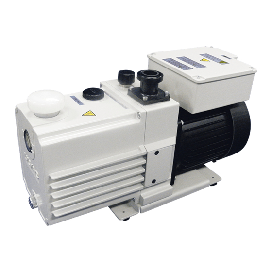
Direct drive oil-sealed rotary vacuum pump
Read this manual before using the product.
Keep it in a safe place ready for use as necessary.
The content of this manual is liable to change without prior notice in
the event of improvements in performance and capabilities.
ULVAC KIKO, Inc.
Model
GHD-101A
GHD-101B
GHD-101C
GHD-101D
No. 1000902-2-01-2
Advertisement
Table of Contents

Related Manuals for Ulvac GHD-101A


Summary of Contents for Ulvac GHD-101A
- Page 1 Read this manual before using the product. Keep it in a safe place ready for use as necessary. The content of this manual is liable to change without prior notice in the event of improvements in performance and capabilities. ULVAC KIKO, Inc.
- Page 2 Attention Copying of any part of this manual for use by a third party is prohibited without permission of Ulvac. -01-...
-
Page 3: Safety Icons
Safety icons This manual and the pump warnings include safety icons to assist in understanding points to be followed. The meanings of these icons are as described below. Danger There is a very real danger of death or serious injury to the operator if the equipment is used incorrectly. -
Page 4: Safety Cautions
Safety cautions Danger Ensure that only dry air or dry nitrogen enters this pump. Danger If the pump has been used to exhaust toxic gases, the pump itself, and the vacuum pump oil (pump oil) will also be toxic. Be aware of this when performing maintenance. Warning Ensure that this pump is dismantled and repaired only by a repair technician. - Page 5 Incorrect wiring work may result in fire. Caution If the pump ceases to operate, or a fault occurs, switch the main power supply off immediately to prevent any accidents, and contact your dealer or Ulvac, for inspection and repair. Attention Do not operate the pump when it doesn’t have any pump oil in it.
-
Page 6: Receiving And Storing The Pump
(3) Check that no damage has occurred in transit. (4) Check that no nuts or bolts have become loose in transit. Have any nuts come off? Contact your dealer or Ulvac if a problem has occurred. 0.4.2 Surroundings during storage, mounting, and operation This pump is designed with very tight tolerances, and the following conditions must therefore be satisfied during storage, mounting, and operation. -
Page 7: Protective Equipment
Attention The pump will be damaged if it is subjected to shock it is overturned. Attention Always use the pump indoors. Attention Pump oil must be put in the pump and the inlet port sealed if storing it unused for a long period of time. -
Page 8: Table Of Contents
Contents 0.Introduction ・・・・・・・・・・ 01 0.1 Before using the vacuum pump ・・・・・・・・・・ 01 0.2 Safety icons ・・・・・・・・・・ 02 0.3 Safety cautions ・・・・・・・・・・ 03 0.4 Receiving and storing the pump ・・・・・・・・・・ 05 0.4.1 Receiving the pump ・・・・・・・・・・ 05 0.4.2 Surroundings during storage, mounting, and operation ・・・・・・・ 05 0.5 Protective Equipment ・・・・・・・・・・... - Page 9 4.Operation ・・・・・・・・・・ 12 4.1 Safety cautions ・・・・・・・・・・ 12 4.2 Starting ・・・・・・・・・・ 13 4.3 Operating when it is cold ・・・・・・・・・・ 13 4.4 Stopping ・・・・・・・・・・ 14 4.5 Backflow prevention device ・・・・・・・・・・ 14 4.6 Thermal protector ・・・・・・・・・・ 14 4.7 Gas ballast valve ・・・・・・・・・・ 15 4.8 Attaching the oil mist trap (option) element ・・・・・・・・・・...
- Page 10 8.Maintenance parts ・・・・・・・・・・ 28 8.1 Maintenance parts list ・・・・・・・・・・ 28 8.2 Disassembly drawings ・・・・・・・・・・ 29 Warranty Safety data sheet (SDS) Conditions of Use Check Sheet (disassembly repair) Sales and Service Contact Addresses Tables and figures ・・・・・・・・・・ Fig. 1 GHD-101 Sealed rotary vacuum pump dimension drawings Fig.
-
Page 11: 0.Introduction
1.Using the pump safely Dangers unique to the pump, and safety measures Read this section thoroughly before operating or inspecting the pump. Understand the potential dangers and methods of avoiding these dangers, before commencing operation. 1.1.1 Leakage of dangerous gases and substances DANGER Primary causes Avoidance and actions to be taken... -
Page 12: Warning
1.1.3 Bursting Warning Primary causes Avoidance and actions to be taken Increased internal pressure, with Internal pressure limit is 0.03 MPa (gauge ⇒ pressure). consequent bursting of the pump. If measurement of the pump exhaust pressure shows a value of 0.03 MPa (gauge pressure), check and remove obstructions to the passage of gas in the exhaust. -
Page 13: 2.Pump Description
2.Pump description Performance details Table 1 Pump performance MODEL GHD-101A GHD-101B GHD-101C GHD-101D Voltage V 115-120 220-240 Frequency Hz 50/60Hz TYPE Gaede type,2-stage, direct-drive Exhaust velocity 100(50Hz)/120(60Hz) L/minute 6.7×10 Ultimate G.V. pressure G.V. open Standard Amount 1000 Ambient temperature 7~40... -
Page 14: Dimension Drawings
Table 2 Motor performance MODEL GHD-101A GHD-101B GHD-101C GHD-101D Voltage V 115-120 220-240 Frequency Hz 50/60 TYPE Single-phase, 300W,2-pole, condenser operation Full-load 5.5 (50Hz) 4.5 (50Hz) 2.5 (50Hz) 2.5 (50Hz) current value A 6.3 (60Hz) 5.3 (60Hz) 2.9 (60Hz) 2.7 (60Hz) -
Page 15: Surroundings During Storage, Mounting, And Operation
3.Installation Installation Select a location with as little dust and humidity as possible for the installation, and ensure that the pump is installed level. Select a location that will enable installation, removal, inspection, and cleaning operations. Pay attention to the ambient temperature, especially when installing the pump inside another device. -
Page 16: Establishing An Exhaust
Establishing an exhaust As this pump is shipped with the correct amount of pump oil inside, ensure that it is transported with the exhaust sealed with an oil cap. Remove this oil cap before starting the pump, and fit either a standard exhaust port or an oil mist trap. (Refer to Fig. -
Page 17: Vacuum Piping
Vacuum piping (1) Remove any powder, dust, or rust from the internal walls of the vacuum chamber, piping, and vacuum valve etc. before connection to the pump. Attention The metal mesh in the inlrt port prevents introduction of foreign matter into the pump. Do not remove it during use. -
Page 18: Wiring
Wiring (1) Check that the power supply voltage and the voltage that the motor uses are the same. (2) This pump rotates clockwise as seen from the front of the pump (level gauge side). (3) An overload protection device (automatic-recovery type thermal protector) is built-in to prevent damage to the motor from over current. - Page 19 Table 3 Electric cord selection criteria Power supply Voltage Temperature Current standard voltage standard standard 10A or more, instantaneous (5sec) 100-120V 125V or more 10A or more 70ºC or 10A or more, instantaneous (5sec) more 200-240V 250V or more 10A or more Install the fuse of 10A - 15A or circuit breaker in the branch circuit of the equipment side.
- Page 20 WARNING Commence wiring work only after removing the power plug or turning it off. Do not carry out wiring work while the wiring is live under any circumstances. Working under such conditions may result in electric shock. Caution Ensure that all wiring work is performed in accordance with electrical equipment standards and internal wiring regulations.
-
Page 21: Fluctuations In The Power Supply Voltage And Frequency
Fluctuations in the power supply voltage and frequency Standard: Rotating electric machine general rules, JIS C 4034-1:1999, JEC-2137-2000. There is no problem to main parts when operated continuously under the voltage and frequency fluctuations in area A, and no problem to main parts when operated under the voltage and frequency fluctuations in area B. -
Page 22: 4.Operation
4.Operation Safety cautions WARNING The pump is not pressure-resistant, and has an internal pressure limit of 0.03 MPa (gauge pressure). Do not operate the pump with the exhaust blocked, or with the passage of gas on the exhaust side obstructed. Under these conditions, the pump pressure increases, and this may cause it to burst, oil to spray out of the oil level gauge, or the motor to become overloaded. -
Page 23: Starting
If the oil temperature exceeds this range, it may indicate that something is wrong with the pump, so please inspect the pump or contact Ulvac. Operating when it is cold The pump may rotate slowly for several minutes and be difficult to start when starting for the first time when used when the ambient temperature is low. -
Page 24: Stopping
Stopping Close the vacuum valve (A), and quickly open the leak valve (B), and turn the pump switch off. After the intake side has returned to atmospheric pressure, close leak valve (B), and seal the intake side. (Refer to Fig. 4.) Caution Failure to do so may result in burns. -
Page 25: Gas Ballast Valve
If the thermal protector is caused to operate, turn the switch off and contact Ulvac. The motor is extremely hot at this time. Do not touch it. (Refer to “6.4 Trouble checklist”.) Caution Failure to do so may result in burns. The pump surfaces become hot (40-80ºC). After stopping, do not touch the motor or pump until they have cooled. -
Page 26: Attaching The Oil Mist Trap (Option) Element
Caution The vacuum pump becomes hot (40-80ºC) during operation. Only touch the valve when operating the gas ballast valve. Always close the gas ballast valve before starting the pump. ATTENTION If the gas ballast valve is left open when condensed gases are not being exhausted from the pump, not only may pump oil be sprayed around and the power be reduced, but the ultimate pressure will also be increased. -
Page 27: Magnetic Coupling
4.10 Magnetic coupling This pump uses a magnetic coupling to transfer the motor power to the pump body without touching it. Caution In the following cases the magnetic power of the magnetic coupling which transfers the motor power may weaken. - When starting the pump after it has been stopped for a long time. -
Page 28: 5.Pump Performance
5.Pump performance Ultimate pressure The “ultimate pressure” referred to in catalogs and this instruction manual means “the lowest pressure attainable when the pump is operated without any gas being introduced through the intake (no-load operation)”. We measure this with a Pirani vacuum gauge at the intake while using the specified pump oil. - Page 29 Fig. 9 Exhaust velocity curve -19-...
-
Page 30: 6.Maintenance, Inspection And Repair
6.Maintenance, inspection and repair Maintenance Check the following at least once every three days when using the pump. (1) Check that the pump oil amount is within the red circle on the oil level gauge. (2) Check that the pump oil is not discolored. (3) Check that there are no abnormal noises. - Page 31 (3) Pump oil amount inspection Add the specified pump oil as necessary to ensure that the pump oil level is always within the red circle on the oil level gauge during operation. (4) Oil leak inspection If oil leaks from the drain plug seal, replace the seal. The necessary o-rings and seals are kept in stock at the service departments listed at the end of this manual.
- Page 32 Danger When requesting Ulvac’s service division for disassembly or repair, always note the gases used, and complete the check list (“Conditions of Use Check Sheet”) at the end of this manual. If the pump has been used to exhaust toxic gases, the pump itself, and the pump oil will also be toxic.
-
Page 33: Pump Oil Change
“1.2 Safety data sheet (SDS)”. Attention Do not use any pump oils other that those specified by Ulvac. Using other oils may cause the pump performance to be reduced and its lifetime to be shortened. - Page 34 < Pump oil change procedure > (1) Open the pump inlet port to the room air and operate the pump for five seconds. This will effectively exhaust any oil remaining in the pump. (2) Remove the standard exhaust port, then remove the drain plug, and empty the oil from the pump.
-
Page 35: Trouble Checklist
Trouble checklist Table 6 Trouble checklist Problem Cause Countermeasure Ref. Pump doesn’t (1) Not connected to power (1) Connect to power supply rotate supply (2) Power supply side switch is (2) Turn the power supply side not on switch on (3) Input power supply voltage (3) Adjust to rated voltage abnormal... - Page 36 (8) Find the leak with a leak pump is leaking detector, etc. and stop it (9) Not using the oil specified by (9) After disassembling and Ulvac repairing the pump, replace with the specified oil (10) Oil is not circulating (10) Disassemble and repair...
-
Page 37: 7.Disposal
7.Disposal Ensure that the pump is disposed of in accordance with national legislation, and as required by your local authority. Caution (1) Engage the services of a specialist contractor for disposal if the pump has been used to exhaust toxic or dangerous gases. The pump body and pump oil become toxic. - Page 38 8.Maintenance parts Maintenance parts list Table 7 GHD-101 Maintenance parts list Product name Q’TY Parts name Air open valve spring Oil seal _SC-13-25-7 Oil seal _VC-12-22-4 Check valve Outlet valve spring Outlet valve O ring (Casing) O ring _S-6 O ring _S-7 O ring _S-16 O ring _S-20 O ring _S-32...
- Page 39 Disassembly drawings Fig. 11 GHD-101 Sealed rotary vacuum pump disassembly drawings -29-...
- Page 40 Malfunctions that occur when the pump is damaged, as a result of being dropped or falling, etc. i) Malfunctions judged by Ulvac technical personnel to be due to conditions of use not suited to the vacuum pump. j) Consumables...
- Page 41 The pump and equipment are not contaminated with substances toxic to humans. Signature Seal Date * To avoid problems when transporting the pump, remove oil from the pump before sending it. * Send this check sheet to Ulvac’s Service Division (CS Center). Refer to the attached list of addresses.
Need help?
Do you have a question about the GHD-101A and is the answer not in the manual?
Questions and answers