Table of Contents
Advertisement
Quick Links
Direct-Drive Oil Sealed Rotary Vacuum Pump
Before using the product, be sure to read this manual.
Keep this manual in a place where it can be referred to at any time
and look after it carefully.
The contents of this instruction manual are subject to change
without prior notice due to improvements in performance and the
functions of the product.
Instruction Manual
for
Model
GCD-051X
GCD-136X
GCD-201X
ULVAC KIKO,Inc.
No.17700-2-01-14
Advertisement
Table of Contents

Related Manuals for Ulvac GCD-051X


Summary of Contents for Ulvac GCD-051X
- Page 1 No.17700-2-01-14 Instruction Manual Direct-Drive Oil Sealed Rotary Vacuum Pump Model GCD-051X GCD-136X GCD-201X Before using the product, be sure to read this manual. Keep this manual in a place where it can be referred to at any time and look after it carefully.
- Page 2 0. Introduction 0.1 Before using the vacuum pump Thank you for purchasing our vacuum pump (hereinafter called “pump”). When you have received the pump, check that the delivered pump is as per your order and that it has not been damaged in transportation, etc.
-
Page 3: Safety Symbols
0.2 Safety symbols In this instruction manual and on warning labels attached to the pump, the following symbols are used so that matters which must be strictly adhered to can be readily understood. These symbols are divided as shown below. Danger When mishandled, there is an imminent danger of the operator suffering a fatal accident or serious injury. -
Page 4: Cautions For Safety
0.3 Cautions for safety Danger When toxic or flammable gases are exhausted from the pump, they may leak not only from the pump outlet but also from the pump unit itself. Take proper measures suitable for the type of gas. Danger After the pump has been used for exhausting toxic gasses, not only the pump itself but also vacuum pump oil (hereinafter called “pump oil”) get toxic. - Page 5 Warning Do not use the pump in an explosive atmosphere. Failure to do so will result in injury or fire. Warning Mount vacuum valve and leak valve between the vacuum chamber and pump. To stop the pump, always close vacuum valve and then open leak valve. If this procedure is neglected, the pump oil fills the cylinder, making restart difficult or causing damage to the pump.
- Page 6 Caution Fluoride rubber material is used for the internal parts of a pump. There are some for which the chemical resistance of Fluoride rubber material is not suitable. Especially, be careful of the following chemical. Ammonia, Acetone, Ethylene oxide, Ethylene diamine, Zinc acetate, Amyl acetate, Aluminum acetate, Isopropyl acetate, Ethyl acetate, Lead acetate, Calcium acetate, Cellosolve Acetate, Nickel acetate, Butyl acetate, Propyl acetate, Methyl acetate, Nitroethane, Nitropropane,...
-
Page 7: Acceptance And Storage Of The Pump
Do not subject the pump to shocks or place the pump on its side. Doing so may damage the pump. 0.5 Protective device The pump is provided with a single-phase 100V 50/60Hz (GCD-051X, 136X), three-phase 200V 50/60Hz (GCD-201X) motor. An overload protector (manually reset thermal protector) is incorporated. -
Page 8: Table Of Contents
3.2 Lubrication ·························· 7 3.3 Vacuum piping ·························· 9 3.4 Electric wiring ·························· 10 3.4.1 GCD-051X・136X ····· 10 (in the case of GCD-201X single phase motor specification) 3.4.2 GCD-201X ··········· 10 (in the case of GCD-136X three phase motor specification)... - Page 9 5. Pump Performance ·························· 18 5.1 Ultimate pressure ·························· 18 5.2 Pumping speed ·························· 18 5.3 Power requirement ·························· 18 6. Maintenance, Inspection and Repair ·························· 20 6.1 Maintenance ·························· 20 6.2 Periodic inspection ·························· 20 6.3 Replacement of the pump oil ··························...
- Page 10 Figures and Tables Fig. 1 Dimensional drawing of GCD-051X oil sealed rotary vacuum pump ········ 4 Fig. 2 Dimensional drawing of GCD-136X oil sealed rotary vacuum pump ········ 5 Fig. 3 Dimensional drawing of GCD-201X oil sealed rotary vacuum pump ········ 6 Fig.
-
Page 11: Introduction
1. For Safe Operation 1.1 Hazards peculiar to the pump and safety measures Before operating or inspecting the pump, read this section carefully to fully understand potential hazards and prevention methods. 1.1.1 Danger Leakage of hazardous gases and substances Cause Prevention method and measures ⇒... -
Page 12: Warning Explosion
1.1.3 Warning Explosion Cause Prevention method and measures ⇒ The maximum internal pump pressure is 0.03 MPa (gauge The pressure in the pump increased causing the pump pressure). to explode. Measure the pressure at the outlet side and, if the pressure is 0.03 MPa or more (gauge pressure), remove objects which block the passage of gas from the outlet side. -
Page 13: Outline Of The Pump
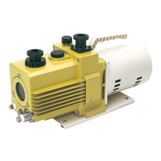
This oil sealed rotary vacuum pump is a rotary vane pump (hereinafter called Gaede type pump) in which the pump is directly driven by the motor. Since the pump is small, light, and quite simply constructed, it is easily maintained and repaired. Table 1 Specification GCD-051X GCD-136X GCD-201X Model... -
Page 14: Dimensional Drawing
2.2 Dimensional drawing Motor ; Single phase, 100V 50/60Hz,110V 60Hz, 200W, 4Poles Weight ; 14.1kg Fig. 1 Dimensional drawing of GCD-051X oil sealed rotary vacuum pump - 4 -... -
Page 15: Fig. 2 Dimensional Drawing Of Gcd-136X Oil Sealed Rotary Vacuum Pump
Motor ; Single phase, 100V 50/60Hz,110V 60Hz 400W, 4Poles, capacitor start and run ; 25.4kg Weight Motor ; three phase, 200V 50/60Hz,220V 60Hz, 400W, 4Poles Weight ; 22.8kg Fig. 2 Dimensional drawing of GCD-136X oil sealed rotary vacuum pump - 5 -... -
Page 16: Fig. 3 Dimensional Drawing Of Gcd-201X Oil Sealed Rotary Vacuum Pump
Motor ; Single phase, 100V 50/60Hz,110V 60Hz 550W, 4Poles, capacitor start and run Weight ; 29.4kg Motor ; three phase, 200V 50/60Hz,220V 60Hz, 700W, 4Poles ; 27.0kg Weight Fig. 3 Dimensional drawing of GCD-201X oil sealed rotary vacuum pump - 6 -... -
Page 17: Installation
3. Installation 3.1 Installation The pump should be installed on a level surface in a location with minimal dust, dirt and humidity and be arranged with consideration given to ease of installation, removal, inspection and cleaning. Particular attention should be paid to the ambient temperature when building the pump into equipment. -
Page 18: Fig. 4 Lubrication Of The Oil Sealed Rotary Vacuum Pump
(1) Oil level shown on the oil level gauge (2) Lubrication method Fig. 4 Lubrication of the oil sealed rotary vacuum pump Caution ① Wear protective equipment such as rubber gloves and safety goggles. ② Be sure to read the attached “Safety Data Sheet” before adding oil. If the oil accidentally comes into contact with your hands or enters your eyes, take proper measures in accordance with the section “First-aid treatment”... -
Page 19: Vacuum Piping
3.3 Vacuum piping (1) Before connecting the pipe to the pump, clean the inner walls of the vacuum chamber, piping and vacuum valve to completely eliminate moisture, fine particles, dust, dirt and rust. Note If fine particles, dust or dirt, etc are evacuated, the pump may malfunction. If moisture is evacuated, not only does the ultimate pressure increase but also the inside of the pump becomes rusty causing the pump to malfunction. -
Page 20: Electric Wiring
3.4 Electric wiring 3.4.1 GCD-051X・136X (in the case of GCD-201X single phase motor specification) (1) This pump has performed beforehand electric wiring by the side of a pump. (2) Please insert the plug of the power cord of a pump in the wall socket of single phase 100V. -
Page 21: Fluctuation In The Power Voltage And Frequency
3.5 Fluctuations in the power voltage and frequency Standard: Rotation electricity machine general rules JIS C 4034-1:1999,JEC-2137-2000 To the voltage change and frequency change in Domain A, in main rated values, it operates continuously, and can be used practically convenient, and to the voltage change and frequency change in Domain B, it shall operate with main rated values and shall be used practically convenient. - Page 22 Warning It will cause a serious damage or movement failure to the motor of GCD-051X in case of impressing the inverter controlled pressure is given towards the motor of GCD-051X itself. Please carefully be noted and do not take the above action.
-
Page 23: Operation
4. Operation 4.1 Cautions for operation Warning There is a risk of explosion. Never block the outlet or operate the pump with equipment mounted at the outlet side which blocks the passage of gas. Otherwise, the pump internal pressure increases causing the pump to explode, the oil level gauge to protrude or the motor to be overloaded. -
Page 24: Start Of Operation
4.2 Start of operation To start operation, close leak valve (B), open vacuum valve (A) to the inlet port, and turn on the power switch. Then the pump starts beings to exhaust (see Fig. 5). Caution ① Firing hazard. Do not touch the motor or the pump body as these surface temperature should be higher (40~80℃). -
Page 25: Operation In Cold Climates
The type of thermal protector to be used depends on the pump model. Table 3 Characteristics of the thermal protector Operating Non-operating Model characteristic characteristic GCD-051X 1φ,200W 25.0(A) at 25℃ 7.0(A) at 60℃ 1φ,400W 28.0(A) at 25℃ 7.8(A) at 60℃... -
Page 26: Gas Ballast Valve
Caution Firing hazard. As the surface of the pump body is higher temperature(40~80℃) during operation, do not touch it until cooled down after stopping the pump. 4.7 Gas ballast valve The pump is equipped with a gas ballast valve in order to evacuate vapor and condensable gases such as solvent vapor. -
Page 27: Installation Of The Oil Mist Separators (Option)
4.8 Installation of the oil mist separators (Option) An oil mist separators can be installed in order to remove oil mist from the pump. In GCD-051X, it is an OMC -050 type, In GCD-136X,201X, they are an OMC-200 type. Attach in the outlet pipe of a pump by quick coupling of KF-25 (NW-25). -
Page 28: Pump Performance
5. Pump Performance 5.1 Ultimate pressure The term “ultimate pressure” as employed in the catalogue and in this manual is defined as “the minimum pressure obtained by the pump without the introduction of gas from the pump inlet (i.e. the non-load condition).” For this pump, measurement is performed using the specified pump oil with only a Pirani vacuum gauge installed at the pump inlet port. -
Page 29: Fig. 8 Pumping Speed Curve
Fig. 8 Pumping speed curve - 19 -... -
Page 30: Maintenance, Inspection And Repair
6. Maintenance, Inspection and Repair 6.1 Maintenance Check the following during operation at least once every three days. (1) Amount of pump oil (To be within the range shown with lines on the oil level gauge) (2) Discoloration of the pump oil (3) Abnormal sound (4) Problem with the motor current value (5) Oil leak from the oil seal... - Page 31 Table 4 Periodic inspection table Frequency Item Details Measures Once/3 Amount Refill the oil. days Color (Reddish brown, dark blown, Replace the oil. and cloudy white are not good.) This pump uses carbon in internal member of framework. Oil may become black when it runs.
-
Page 32: Replacement Of The Pump Oil
6) Inspection of the coupling spider Check the spider of the coupling which connects the main pump unit and motor of the pump for damage. If cracks or fractures are found on the spider, replace it in accordance with “6.4 Replacement of the coupling spider.”... - Page 33 Danger Keep in mind that if the pump is used for exhausting toxic gas, both the main pump unit and pump oil will become contaminated. Caution ① Wear protective equipment such as rubber gloves and safety goggles. ② Be sure to read the attached “Safety Data Sheet” before adding oil. If the oil accidentally comes into contact with your hands or enters your eyes, take proper measures in accordance with the section “First-aid treatment”...
-
Page 34: Replacement Of The Coupling Spider
6.4 Replacement of the coupling spider A rubber spider is used at the section connecting the pump main unit and the motor. It is recommended that this spider be periodically inspected once a year or so. If the corner is chipped or cracked, replace it. -
Page 35: Trouble Check List
6.5 Trouble check list Table 5 Trouble check list Problem Cause Measures Reference ① The pump is not connected to the ① Connect the pump to the power The pump does not rotate. power supply. supply. ② The power switch is not turned on. ②... - Page 36 Problem Cause Measures Reference ⑥ The specified amount of oil has not ⑥ Add the specified amount of oil. The pressure does not been added. decrease. ⑦ The oil has deteriorated. ⑦ Replace the oil. ⑧ Leakage occurs from the pipe ⑧...
-
Page 37: Disposal
7. Disposal Follow state law and local government regulations for disposal of the pump. Caution ① When a harmful toxic gas has been exhausted, ask a specialist for waste disposal. Not only the pump itself but also the pump oil become toxic. ②... -
Page 38: Maintenance Prats
8. Maintenance parts 8.1 Maintenance parts list Table 6 GCD-051X Maintenance parts list Product name Prats name Q’ty Outlet valve Outlet valve spring Check valve Check valve spring Oil seal_HTC-11-25-7 Oil seal_SC-12-25-7 Oil seal_VC-12-22-4 Oil seal_VC-10-20-4 O-ring _S-3 O-ring _S-5... - Page 39 Table 7 GCD-136X Maintenance parts list Product name Prats name Q’ty Outlet valve Outlet valve spring Check valve Check valve spring Oil seal_HTC-17-40-9 Oil seal_SC-17-30-7 Oil seal_SC-15-30-7 - O-ring _P-6 - O-ring _P-7 O-ring _P-12 O-ring _P-20 O-ring _P-34 GCD-136X Maintenance kit A O-ring _P-35 O-ring _S-10...
- Page 40 Table 8 GCD-201X Maintenance parts list Product name Prats name Q’ty Outlet valve Outlet valve spring Check valve Check valve spring Oil seal_HTC-17-40-9 Oil seal_SC-17-30-7 Oil seal_SC-15-30-7 - O-ring _P-6 - O-ring _P-7 O-ring _P-12 O-ring _P-20 O-ring _P-34 GCD-201X Maintenance kit A O-ring _P-35 O-ring _S-10...
-
Page 41: Disassembly Drawing
8.2 Disassembly drawing Fig. 10 Disassembly drawing of GCD-051X oil sealed rotary vacuum pump - 31 -... -
Page 42: Fig. 11 Disassembly Drawing Of Gcd-136X Oil Sealed Rotary Vacuum Pump
Fig. 11 Disassembly drawing of GCD-136X oil sealed rotary vacuum pump - 32 -... -
Page 43: Fig. 12 Disassembly Drawing Of Gcd-201X Oil Sealed Rotary Vacuum Pump
Fig. 12 Disassembly drawing of GCD-201X oil sealed rotary vacuum pump - 33 -... -
Page 44: Warranty
Warranty (1) The warranty for this pump (this equipment) extends for a period of one year from the date of shipment. (2) Any malfunctions or defects which occur under normal usage conditions during the warranty period will be repaired free of charge. Note, the warranty stated here is an individual warranty covering the pump. -
Page 45: Usage Status Check Sheet (For Use In Instruction Manual)
Usage Status Check Sheet (for use in Instruction Manual) * For the purpose of safety control of repair personnel, fill in within the heavy line frame and attach the sheet to the item of which repair is requested. * In case this sheet were not attached or filled in, your request of repair and service may not be accepted. * In accordance with the Private Information Protection Law, the provided information will be used only for determining the cause of failure and whether detoxifying washing should be conducted.
Need help?
Do you have a question about the GCD-051X and is the answer not in the manual?
Questions and answers
what is the price of oil taker filter and true
@SOHAN I need separate all parts prices of this model. Please kindly inform me
@SOHAN Oil Rotary Vacuum Pump Anti-corrsive Type Model:GCD-051X separate all parts prices