Vulcan-Hart C24EA3 Service Manual
C24ea series atmospheric steamers
Hide thumbs
Also See for C24EA3:
- Installation & operation manual (48 pages) ,
- Brochure (9 pages) ,
- Specifications (2 pages)
Table of Contents
Advertisement
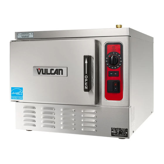
C24EA3 BASIC SHOWN
This Manual is prepared for the use of trained Vulcan Service
Technicians and should not be used by those not properly
qualified. If you have attended a Vulcan Service School for this
product, you may be qualified to perform all the procedures
described in this manual.
This manual is not intended to be all encompassing. If you have
not attended a Vulcan Service School for this product, you should
read, in its entirety, the repair procedure you wish to perform to
determine if you have the necessary tools, instruments and skills
required to perform the procedure. Procedures for which you do
not have the necessary tools, instruments and skills should be
performed by a trained Vulcan Service Technician.
Reproduction or other use of this Manual, without the express
written consent of Vulcan, is prohibited.
For additional information on Vulcan-Hart Company or to locate an authorized
parts and service provider in your area, visit our website at www.vulcanhart.com
A product of VULCAN-HART
SERVICE MANUAL
C24EA SERIES
ATMOSPHERIC
STEAMERS
C24EA3 208/240V PRO
C24EA3 480V PRO
C24EA5 208/240V PRO
C24EA5 480V PRO
C24EA3 208/240V BASIC
C24EA3 480V BASIC
C24EA5 208/240V BASIC
C24EA5 480V BASIC
- NOTICE -
ML-136037
ML-136044
ML-136038
ML-136047
ML-136043
ML-136045
ML-136046
ML-136048
LOUISVILLE, KY 40201-0696
F25213 (May 2006)
Advertisement
Table of Contents

Related Manuals for Vulcan-Hart C24EA3


Summary of Contents for Vulcan-Hart C24EA3
- Page 1 C24EA3 BASIC SHOWN This Manual is prepared for the use of trained Vulcan Service Technicians and should not be used by those not properly qualified. If you have attended a Vulcan Service School for this product, you may be qualified to perform all the procedures described in this manual.
-
Page 2: Table Of Contents
CONDENSED SPARE PARTS LIST ............52 ©VULCAN 2006... -
Page 3: General
The generator element will shut off when the door is opened then re-start when the door is closed. MODELS COVERED Model Designations (based on 2.5 inch pan depth) C24EA3 Three pan - Basic or Professional C24EA5 Five pan - Basic or Professional GENERAL... -
Page 4: Specifications
These problems are common to any manufacturer's steamer regardless of design, but they can all be prevented by furnishing the steam generator tank with properly conditioned water. Vulcan recommends the water contain less than 60ppm of total dissolved solids (TDS) and have a PH factor between 6.5 to 8. - Page 5 Other chemical properties in water supplies can also affect good steam generation and vary from within each state and locality. The water level probes in the steam generator tank use ions in the water to detect the water level. Do not use fully demineralized or de-ionized water since it is non-conductive and the water level can not be detected.
-
Page 6: Covers And Panels
COVERS AND PANELS WARNING: DISCONNECT THE ELECTRICAL POWER TO THE MACHINE AND FOLLOW LOCKOUT / TAGOUT PROCEDURES. RIGHT AND LEFT SIDE PANELS NOTE: Removal of left side panel is identical to the procedure for the right side panel. Remove screws from the bottom of panel being removed. - Page 7 REAR PANEL WARNING: DISCONNECT THE ELECTRICAL POWER TO THE MACHINE AND FOLLOW LOCKOUT / TAGOUT PROCEDURES. Remove screws securing top cover to rear panel and rear panel to steamer frame. SCREW LOCATION NOTE: If incoming plumbing or drain interferes with rear panel removal, turn off water supply and disconnect plumbing to machine.
-
Page 8: Door
WARNING: DISCONNECT THE ELECTRICAL POWER TO THE MACHINE AND FOLLOW LOCKOUT / TAGOUT PROCEDURES. REMOVAL Close door. Remove LEFT SIDE PANEL as outlined in COVERS AND PANELS. Remove nuts from upper hinge located inside front panel. Open door slightly, and while holding door, pull upper hinge away from front panel. - Page 9 DOOR HANDLE Removal Open door. Remove screws from top and bottom of door assembly. Pull outer door housing away from inner door panel starting at the hinge side of door to separate the door halves. NOTE: The smaller radius of the step spacers fit into the slots of the outer door housing and is used to provide clearance for handle operation.
- Page 10 LATCH ASSEMBLY Removal and Disassembly Separate outer door housing assembly from inner door panel as outlined under DOOR HANDLE. Remove screws securing latch assembly to inner door panel and remove latch mechanism. Remove E-clip from latch assembly pins and pull pins from latch mechanism. Remove retaining pin from spring pin.
-
Page 11: Door Latch Adjustment
Install outer door housing assembly as outlined in DOOR HANDLE. Check opening and closing operation of door. Check steamer for proper operation and leaks around door seal. HINGE BEARINGS Close door. Remove LEFT SIDE PANEL as outlined in COVERS AND PANELS. Remove nuts from upper hinge located inside front panel. -
Page 12: Drain
Adjustment Reinstall striker with slot pointing upward and hand tighten nut only. Close door to center striker in front panel mounting hole. Open door and check striker slot for horizontal alignment. The slot on striker must be kept horizontal in order for door latch to catch properly and latch. -
Page 13: Cooking Compartment
COOKING COMPARTMENT WARNING: DISCONNECT THE ELECTRICAL POWER TO THE MACHINE AND FOLLOW LOCKOUT / TAGOUT PROCEDURES. REMOVAL AND REPLACEMENT NOTE: The cooking compartment and front panel are constructed as an assembly and cannot be separated. Turn off machine to drain steam generator tank. Allow steamer to complete drain cycle. - Page 14 Remove the screws securing front panel to lower louvered panel. Remove the nuts securing rear of cooking compartment to the vertical mounting brackets (four places - located between cooking compartment and steam generator). 10. Remove cooking compartment assembly. 11. If removed or replacing cooking compartment, install insulation around cooking compartment.
-
Page 15: Thermostats
HOLD THERMOSTAT WARNING: DISCONNECT THE ELECTRICAL POWER TO THE MACHINE AND FOLLOW LOCKOUT / TAGOUT PROCEDURES. Turn off machine to drain steam generator tank. Allow steamer to complete drain cycle. Turn off water supply. Remove RIGHT SIDE PANEL as outlined under COVERS AND PANELS. -
Page 16: Condensate Thermostat
Installation Insert capillary bulb through large compression nut. Route capillary bulb through top of heating element. Position capillary bulb between top of second and third heating element coils. Secure with hose clamp to second coil as shown. Apply pipe thread sealant to threads of large capillary nut then install large compression nut. -
Page 17: Timer
WARNING: DISCONNECT THE ELECTRICAL POWER TO THE MACHINE AND FOLLOW LOCKOUT / TAGOUT PROCEDURES. REMOVAL AND REPLACEMENT NOTE: The basic and professional model steamers use the same 60 minute timer. When the timer reaches zero, an external buzzer will sound and steam will stop entering the cooking compartment. -
Page 18: Heating Element
WARNING: DISCONNECT THE ELECTRICAL POWER TO THE MACHINE AND FOLLOW LOCKOUT / TAGOUT PROCEDURES. REMOVAL AND REPLACEMENT Turn off machine to drain steam generator tank. Allow steamer to complete drain cycle. Turn off water supply. Remove RIGHT SIDE PANEL and TOP COVER as outlined under COVERS AND PANELS. - Page 19 Reassemble parts removed in reverse order of removal. Tighten heating element screws evenly to 70 in*lbs. Follow tightening sequence pattern as shown in illustration. OVERHEAD VIEW OF HEATING ELEMENT 10. Check steamer for proper operation and leaks around heating element. DIAGNOSTIC CHECKS WARNING: CERTAIN PROCEDURES IN THIS SECTION REQUIRE ELECTRICAL TEST OR MEASUREMENTS WHILE POWER IS APPLIED TO THE MACHINE.
-
Page 20: Super Heater
WARNING: DISCONNECT THE ELECTRICAL POWER TO THE MACHINE AND FOLLOW LOCKOUT / TAGOUT PROCEDURES. REMOVAL AND REPLACEMENT Turn off machine to drain steam generator tank. Allow steamer to complete drain cycle. Turn off water supply. Remove RIGHT SIDE PANEL as outlined under COVERS AND PANELS. - Page 21 DIAGNOSTIC CHECKS WARNING: CERTAIN PROCEDURES IN THIS SECTION REQUIRE ELECTRICAL TEST OR MEASUREMENTS WHILE POWER IS APPLIED TO THE MACHINE. EXERCISE EXTREME CAUTION AT ALL TIMES. IF TEST POINTS ARE NOT EASILY ACCESSIBLE, DISCONNECT POWER AND FOLLOW LOCKOUT / TAGOUT PROCEDURES, ATTACH TEST EQUIPMENT AND REAPPLY POWER TO TEST.
-
Page 22: Water Level Control Components
WATER LEVEL CONTROL COMPONENTS WATER LEVEL CONTROLS Low Level Cut-Off & Differential Control The steamer is equipped with three water level sensing probes (high, low and low level cut-off) and a water level control board. The water level control board performs two functions: 1) Provide low level cut-off protection to shut off the heat source in case the water level drops below the low level cut-off (LLCO) probe. -
Page 23: Water Level Control Board
WATER LEVEL CONTROL BOARD WARNING: DISCONNECT THE ELECTRICAL POWER TO THE MACHINE AND FOLLOW LOCKOUT / TAGOUT PROCEDURES. CAUTION: Certain components in this system are subject to damage by electrostatic discharge during field repairs. A field service grounding kit is available to prevent damage. The field service grounding kit must be used anytime the control board is handled. -
Page 24: Filtered And Non-Filtered Water Solenoid Valves
NOTE: Perform a steam generator tank cleaning as outlined under STEAM GENERATOR TANK - CLEANING. FILTERED AND NON-FILTERED WATER SOLENOID VALVES WARNING: DISCONNECT THE ELECTRICAL POWER TO THE MACHINE AND FOLLOW LOCKOUT / TAGOUT PROCEDURES. NOTE: The filtered and non-filtered water solenoid valves are constructed as dual water valve assemblies. -
Page 25: Manual Drain Valve (Basic)
Reassemble parts removed in reverse order of removal. Verify that the filtered water supply is connected to the input of the filtered water solenoid valve. Check steamer for leaks and proper operation. Non-Filtered Cold Water Solenoid Valve Turn off machine to drain steam generator tank. Allow steamer to complete drain cycle. -
Page 26: Motorized Drain Valve (Professional)
NOTE: Apply pipe thread sealant to plumbing threads before assembly. Reassemble parts removed in reverse order of removal. For Basic model steamers, perform ON/OFF SWITCH ADJUSTMENT as outlined in ON/OFF SWITCH. Check steamer for leaks and proper operation. MOTORIZED DRAIN VALVE (PROFESSIONAL) WARNING: DISCONNECT THE ELECTRICAL POWER TO THE... - Page 27 Disconnect the drain and drain flush hoses from the Tee located below the drain valve. Remove the drain valve body from the steam generator tank. Separate the Tee and nipple from the drain valve body. Reassemble parts removed in reverse order. Apply liquid pipe thread sealant to threads of plumbing connections.
-
Page 28: Switches, Buzzer And Solenoids
SWITCHES, BUZZER AND SOLENOIDS ON/OFF SWITCH WARNING: DISCONNECT THE ELECTRICAL POWER TO THE MACHINE AND FOLLOW LOCKOUT / TAGOUT PROCEDURES. Basic Models Pull out on handle to turn steamer off and drain generator tank. Remove the RIGHT SIDE PANEL. Locate the on/off switch assembly mounted to the manual drain valve. -
Page 29: Door Switch
Push handle fully in and keep in position. Position plunger of on/off switch against linkage bracket such that plunger is fully engaged. Adjust switch such that switch plunger is perpendicular with linkage bracket when handle is pushed in fully. Tighten switch mounting screws. Professional Models Remove the RIGHT SIDE PANEL. -
Page 30: Pressure Switch
Close door. Push switch up against switch linkage as far as possible. Tighten switch mounting hardware. Check door switch operation. Set meter to measure resistance and place meter leads across the COMMON and NORM OPEN terminals of switch. With door closed, meter should indicate a closed circuit. - Page 31 Perform pressure switch Check. Check NOTE: Pressure can be checked with the small air pocket that exists between the delime port cap and water level probe housing in the delime hose. Make certain that no leaks exist in generator tank or pressure gauge fittings.
-
Page 32: Vacuum Relief Solenoid
Repeat clamping of steam outlet hose a total of three times to find the average cut- out pressure. Record pressure. If pressure is outside tolerance (4.5 to 4.7 psi), adjustment is necessary. Refer to Adjustment. If cut-out pressure is within specifications, shut off steamer. -
Page 33: Buzzer
Install valve with the inlet (ON) side of valve connected to the back panel port and the outlet (OFF) side of valve connected to the water level control plumbing. Apply liquid thread sealant to threads of piping before assembly. BUZZER WARNING: DISCONNECT THE ELECTRICAL POWER TO THE MACHINE AND FOLLOW LOCKOUT /... -
Page 34: Steam Generator Tank
STEAM GENERATOR TANK WARNING: DISCONNECT THE ELECTRICAL POWER TO THE MACHINE AND FOLLOW LOCKOUT / TAGOUT PROCEDURES. REMOVAL AND REPLACEMENT Turn off machine to drain steam generator tank. Allow steamer to complete drain cycle. Turn off water supply. Remove the TOP COVER, RIGHT and REAR PANEL as outlined under COVERS AND PANELS. - Page 35 10. Remove remaining steam outlet elbow plumbing from steam generator tank. 11. Remove delime hose from water level probe assembly. 12. Remove hose from the vacuum relief solenoid. 13. Note wiring connection points and remove the electrical wires from the VACUUM RELIEF SOLENOID, WATER LEVEL PROBES and PRESSURE SWITCH.
-
Page 36: Electrical Operation
ELECTRICAL OPERATION COMPONENT FUNCTION Water Level Control (WLC) Board ..Controls water level by monitoring conditions of the three water Buzzer ....... . Creates audible signal when timed cook cycle is complete. Contactor, Limiting . - Page 37 Solenoid (4SOL), Slow Fill ....Primary fill for Basic machines and secondary fill for Solenoid (5SOL), Vacuum Relief ... Provides open air line for vacuum relief during drain cycle to Switch (1S), Power .
-
Page 38: Component Location
MODEL C24EA - ELECTRICAL OPERATION COMPONENT LOCATION Electrical Control Panel NOTE: Relay K4 and transformer T2 are present on Professional models only. F25213 (May 2006) Page 38 of 52... - Page 39 MODEL C24EA - ELECTRICAL OPERATION Water Level Control Board Page 39 of 52 F25213 (May 2006)
- Page 40 MODEL C24EA - ELECTRICAL OPERATION Front Panel F25213 (May 2006) Page 40 of 52...
- Page 41 MODEL C24EA - ELECTRICAL OPERATION Steam Generator and Back Panel Page 41 of 52 F25213 (May 2006)
-
Page 42: Sequence Of Operation
SEQUENCE OF OPERATION Refer to the correct wiring diagram for model being serviced when reviewing sequence of operation. NOTE: If power switch is set to off when service voltage is applied, steamer will enter the timed drain cycle. Basic Model Conditions Steamer connected to correct voltage. - Page 43 Time delay relay is energized through terminals 2 & 3 for set time (90 seconds). Output (120VAC) on terminal 1. Time delay relay output energizes K3 coil. X1 potential to L1 of WLC board through N.O. contacts K3-5/3 LLCO relay K2 coil energized through closed N.O.
- Page 44 No action as internal latching relay (ILR-1) contacts are open. Water level reaches high level(H) probe. Internal latching relay (ILR) coil on WLC board energizes. High level (HL) coil de-energized by ILR-2 contacts opening. Slow Fill Solenoid de-energized by opening of HL contacts on WLC board.
-
Page 45: Wiring Diagrams
MODEL C24EA - ELECTRICAL OPERATION WIRING DIAGRAMS Heating Element Wiring Page 45 of 52 F25213 (May 2006) - Page 46 MODEL C24EA - ELECTRICAL OPERATION F25213 (May 2006) Page 46 of 52...
- Page 47 MODEL C24EA - ELECTRICAL OPERATION Page 47 of 52 F25213 (May 2006)
- Page 48 MODEL C24EA - ELECTRICAL OPERATION F25213 (May 2006) Page 48 of 52...
- Page 49 MODEL C24EA - ELECTRICAL OPERATION Page 49 of 52 F25213 (May 2006)
-
Page 50: Troubleshooting
SYMPTOM Compartment leaks water around door. Cold water condenser not operating properly. Steam leaks around door. Steam generated inside cooking compartment when timer is off. Steam leaking inside panels. Heat coming on without water in tank. Machine will not heat. Steamer leaks water. - Page 51 MODEL C24EA - TROUBLESHOOTING - N O T E S - Page 51 of 52 F25213 (May 2006)
-
Page 52: Condensed Spare Parts List
CONDENSED SPARE PARTS LIST PART NO. 844069-1 Water Level Control Board (WLC) 856658-1 Cavity Vacuum Breaker 294500-33 Transformer 410472-8 Terminal Block - Main 411500-12 Transformer (2T) 416535-6 Relay 855661-1 Time Delay Relay 881654 Contactor FE-024-94 Fuse, 250V, 4A (slow blow) 294436-3 Fuse Block 856621-1...
Need help?
Do you have a question about the C24EA3 and is the answer not in the manual?
Questions and answers